Husky Integration

To attach custom hardware to Husky, you will have to take care of mechanical mounting, electrical supply, and software integration. This guide aims to equip you with respect to these challenges.
Mechanical Mounting
When determining mechanical mounting, you have two options, both of which are described below.
- the "Standard" aluminum extrusion interface
- the "PACS™" mounting system and associated kits
Mechanical, Standard
A standard Husky is delivered with a 20 X 20 aluminum extrusion frame around the top of the user bay. This can be used for mouning sensors, lights, and other small attachments. We suggest using the following items to interface with this extrusion:
| Description | CPR Item | Manufacturer | Manufacturer Item |
|---|---|---|---|
| 20 X 20 Aluminum Extrusion | Misumi | HFSB5-2020 | |
| 20 X 20 Plasic End Cap | 000232 | Misumi | HFC5-2020-B |
| Extrusion Corner Bracket, Blind | 000228 | Misumi | SHBLBS5 |
| Extrusion Stud, M5×0.8 | 001018 | Misumi | HNTLSN5-5-12 |
| Extrusion Nut, M5×0.8 | 026955 | Misumi | SHNTAP5-5 |
| Anchor, Cable Tie | 010439 | McMaster | 7582K65 |
| Screw, M5×0.8, Stainless Steel (assorted lengths) | 023314 - 023324 | McMaster | Many |
| Nut, M5×0.8, Stainless Steel | 015175 | McMaster | 94205A240 |
Misumi also offers a range of configurable products for this 20 X 20 extrusion that can help with your integration.
Mechanical, PACS™
PACS™ is a Clearpath Robotics standard. We add a grid of M5×0.8 holes onto the top plate of the robot. This grid of holes has a 80 mm X 80 mm spacing. You can create your own brackets to interface with these holes, or can use an existing Clearpath Robotics designed bracket.
Our Sensors and Accessories pages indicate the required bracket for the particular attachment.
Refer to the following pages for Husky brackets that can simplify your integration.
- Top Plate
- Weatherproofing Cover
- Riser, Full
- Riser, Partial
- Riser, Stiffener
- Electronics Rack
- OutdoorNav Starter Kit
Electrical Integration
Except for bus-powered USB cameras, most payloads have separate leads for power and data.
Data Connections
Data connections (USB and Ethernet) are made to the Husky computer mounted in the user bay. In addition, the PCIe Gen3 x16 slot may be used to supply a GPU or other attachements, as necessary. Additionally, the user bay may be used for an Ethernet switch, when attaching multiple Ethernet payloads, or for a PoE power injector as required.
User Bay Power Connections
The user bay power connections are capable of supplying:
- VBAT (approximately 24-29 V, unregulated) fused at 5 A
- 12 V fused at 7.5 A
- 24 V fused at 3 A.
In total, 282 W of power is available from these User Power breakouts.
You can order a upgrade for your Husky, that will add 480 W of power (VBAT fused at 20 A). Each terminal comes equipped with a removable connector into which your payload power leads may connect.
Husky UGVs with serial numbers lower than A200-0802 have different user power connections.
These older robots have 5 V, 12 V, and 24 V supplies, all fused at 5A.
Your Husky's serial number is shown on a sticker, attached to the right side of the robot.
To connect to user power:
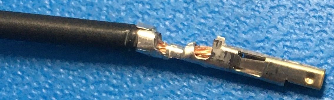
- Expose about 5 mm of bare wire from the payload power leads and twist the exposed wire on both leads.
- Take 2 Molex terminals from the spare parts kit provided and insert the exposed wire and crimp the terminals, ensuring the wires are well secured inside the terminal, as shown below.
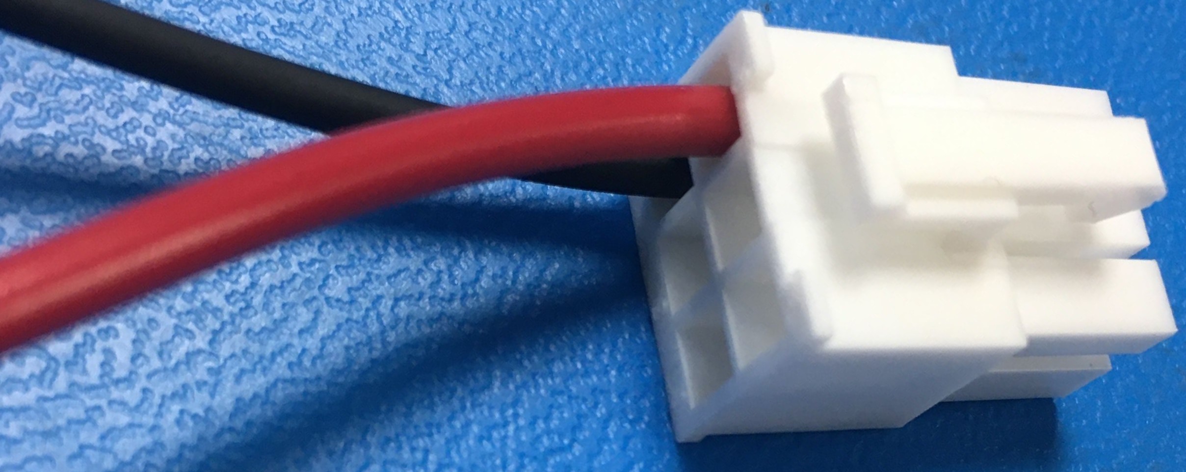
- Take 1 connector housing from the spare parts kit provided and insert the positive payload power lead (red) into position 4, 5, or 6 of the connector until it locks into place. The positions numbers are visible on the back of the plastic housing.
- Insert the negative payload power lead (black) into position 1, 2, or 3 of the connector until it locks into place.
When connecting payloads, be sure to observe correct polarity as marked on the inside of the user bay. Do not exceed the specified maximum current limit of each power rail; failure to do so may result in damage to Husky or your payload.
For more technical information on the Molex power connectors, as well as their corresponding mating connectors, please visit the Digi-Key WM23702-ND Product Page.
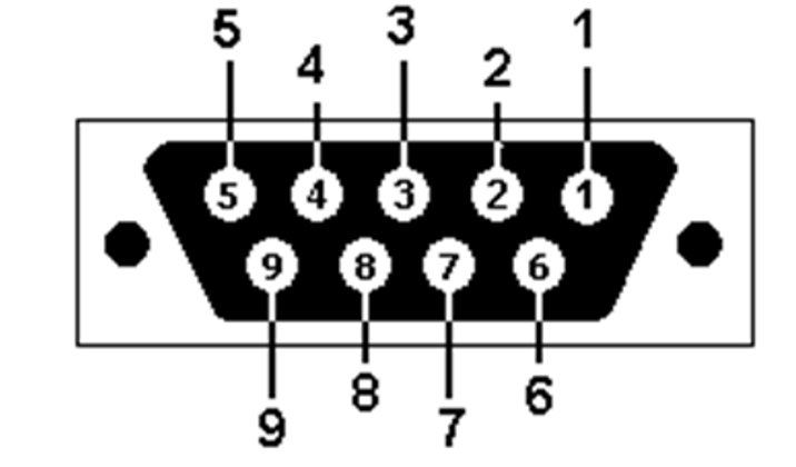
Serial Connection
The pinout of the DE-9 connector is shown below.
 |
|
External Motion Stop
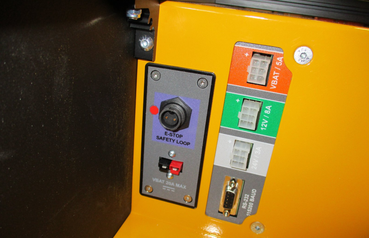
There is a connector labeled E-STOP SAFETY LOOP that is inside the Husky's user bay. The connector has 2 contacts that lead to the Husky MCU circuit board. The MCU supplies +12 V on one of these leads, and monitors the voltage on the other lead. The MCU will place the Husky in a Stop state if the monitored line is below +12 V.
Your robot may have a connector that adds a jumper wire between these 2 leads to complete the circuit; or your robot may have more Stop switches in series with this circuit. These additional components in series may be:
- Emergency Stop buttons
- Wireless Stop receivers
- Relays or similar PLC components
- Manipulator control cabinets
- The connector labeled E-STOP SAFETY LOOP is a Switchcraft EN3P2FX
- The mating connector is a Switchcraft EN3C2MX ( Clearpath Robotics item 008075 )
This was an optional upgrade kit on Huskies built before March 2023. Clearpath Robotics still offers this upgrade kit to add an external motion stop to an older Husky. Contact Support for details.
This is a single channel Stop loop, being monitored by a microcontroller. When the microcontroller is in a Stop state; it will open relays which supply power to the Husky's motor controllers. These relays are not force guided or monitored.
Please contact Support if you need more information for your application's risk assessment.
MCU Debug LEDs
The Husky MCU PCBA comes equipped with LEDs for debugging. They work as follows:
- D16: HEARTBEAT: toggles every 500 ms when the main firmware loop on the MCU is running.
- D7: VBAT 20 A: illuminated if the VBAT, 20 A fuse is good. This LED will be off if the fuse is blown.
- D8: VBAT 5 A: illuminated if the VBAT, 5 A fuse is good. This LED will be off if the fuse is blown.
- D12: 12 V 7.5 A: illuminated if the 12 V, 7.5 A fuse is good. This LED will be off if the fuse is blown.
- D10: 24 V 3 A: illuminated if the 24 V, 3 A fuse is good. This LED will be off if the fuse is blown.
On older revisions of the Husky MCU PCBA, the labels are different, but the functionality is similar:
- D5: HEARTBEAT
- D2: VBAT, 5 A
- D3: 12 V, 5 A
- D4: 5 V, 5 A
Software Integration
ROS has a large ecosystem of sensor drivers, some of which include pre-made URDF descriptions and even simulation configurations. Refer to Sensors supported by ROS.
For the best experience, consider purchasing supported accessories from Clearpath Robotics for your robot, which will include simulation, visualization, and driver support.
Refer to the following for more details:
Support
Clearpath is committed to your success. Please get in touch with us and we will do our best to get you rolling again quickly: support@clearpathrobotics.com.
To get in touch with a salesperson regarding Clearpath Robotics products, please email research-sales@clearpathrobotics.com.
If you have an issue that is specifically about ROS and is something which may be of interest to the broader community, consider asking it on https://robotics.stackexchange.com. If you do not get a satisfactory response, please ping us and include a link to your question as posted there. If appropriate, we will answer in the ROS Answers context for the benefit of the community.