Warthog User Manual
Introduction
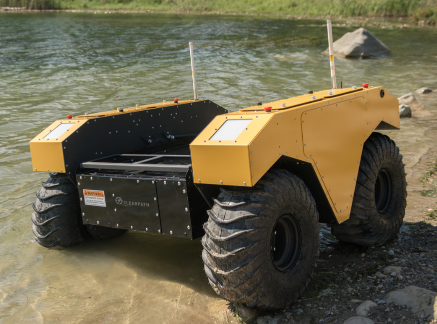
Clearpath Robotics Warthog is a rugged, all-terrain unmanned ground vehicle capable of brief periods of locomotion in water. Warthog fully supports the Robot Operating System (ROS) and can be equipped with a variety of payloads, including sensors and manipulators, to accommodate a wide range of robotics applications in mining, agriculture and environmental monitoring.
Shipment Contents
Your Warthog shipment contains the following:
- Warthog UGV
- Onboard computer
- User Breakout Panel with power, Ethernet, Serial (RS232) and USB connectivity
- 48 V Lead-Acid Battery Pack or 48 V LiFEPO4 Battery Pack
- One battery charger
- One Futaba remote control
- One Warthog quick start guide
- One Wireless Stop remote
If you purchased standard payload modules or custom integration services with Warthog, then additional equipment will be included per your specific configuration, plus further documentation as required.
Hardware Overview
System Architecture
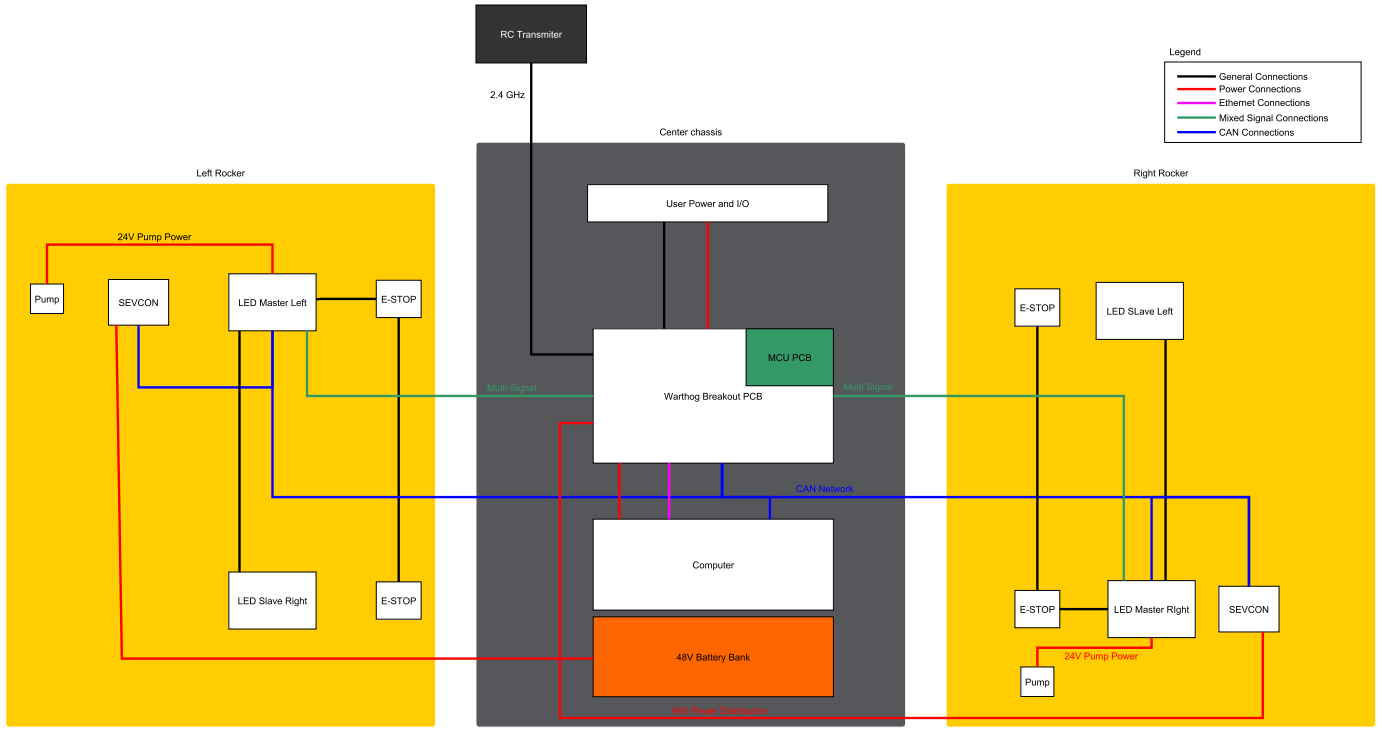
Warthog is built around an onboard computer running Ubuntu (Intel-based computer or Jetson developer kit), paired with a 32-bit microcontroller MCU. The MCU handles IO, system and battery monitoring, and provides an interface to the CAN-controlled motor drivers. The communication channel between the MCU and computer is an Ethernet connection.
System Features
The Warthog is shown below and includes:
- Battery charger access
- Bilge pumps
- User breakouts
- Payload integration area
- Four Stop buttons (one on each corner)
- Four body lights (one on each corner)

Battery Charger Access
Please review this PDF for information about the provided charger.
Bilge Pumps
The Warthog has two bilge pumps, with one situated in each of the drive units underneath the motor. The bilge pumps are used to remove water from the main chassis and drive units during operation in water. At initial startup, an audible sound can be heard from the bilge pumps being initiated. These pumps are an automatic pumping system that check for water levels inside the drive units. The pumps automatically come on every two minutes and check for water levels. If the water level inside the drive unit exceeds a predetermined level, the pumps will remain on, otherwise they will shut off. During prolonged use in water, some water may appear in the drive unit. This is normal and acceptable. This outlet leads from the pump to the exterior of the Warthog. It is used to remove excess water from the chassis and drive units. No obstructions should be placed in front of or around this area. Obstruction of water flow may result in damage to the internal electrical components and loss of function in the Warthog.
User Breakouts
The User Breakout Panel provides access to the user power panel, as well as USB, serial, and ethernet ports. The power panel can be used to power your payloads. The USB 3.0 and Ethernet ports are connected directly to the onboard computer. To connect a device to the onboard network, it's suggested to give it a static IP in the 192.168.131.xxx subnet, avoiding IPs in use by the following pre-existing devices:
| IP address | Description |
|---|---|
| 192.168.131.1 | Onboard Computer (all ports, br0 network interface) |
| 192.168.131.2 | Ethernet-connected MCU |
Typically addresses numbered 192.168.131.100 and above will not collide with any of Warthog's payloads. Please see Electrical Integration for more information.
Payload Integration Area
All payloads should be mounted to the central chassis when traversing through water to prevent rolling. The primary payload of the unit should be placed on the central chassis. If necessary loading can be placed on the drive units however payloads should not exceed 23 kg (50 lbs) on each drive unit.
For more information and guidance on mounting payload structures on top of Warthog, please refer to subsection Mechanical Mounting.
Body Lights
Warthog includes four RGB body lights, one on each corner of the chassis. These lights express system status according to the table below, but in the absence of one of the low-level conditions, they can be commanded from ROS to display indications from autonomy or other higher-level software. See http://wiki.ros.org/warthog_base for information on commanding the body lights.
| Front Lights | Rear Lights | System State |
|---|---|---|
| Solid red | Solid red | The MCU is not in contact with the computer. That is, the rosserial connection is not active. This condition will be seen briefly on startup while Warthog's computer is booting up. If it persists, or is seen after initialization, either the base node on the computer has crashed, the network switch has failed, or a serious MCU error has occurred. If you suspect one of these conditions, please contact support. |
| Flashing red | Flashing red | Stop mode is engaged. To disengage, twist the mushroom buttons on the Warthog and on the Wireless Stop remote to ensure that they are unlatched. See also Using the Wireless Stop Remote. |
| Flashing orange | Flashing orange | Motor drivers not yet ready to drive. The motors have a brief initialization sequence which must complete after a stop condition clears before they are ready to drive. If this condition persists, please contact our support team. |
| Pulsing orange | Pulsing orange | Battery is low. Connect Warthog to the charger. |
| Solid white | Solid red | Normal operation; Warthog is ready to drive. This status may be overridden by publishing your own light patterns to the /cmd_lights ROS topic. |
Orientation References
The reference frame used by all Clearpath Robotics ground robots is based on ISO 8855. When commanded with a positive translational velocity (forward), wheels travel in the positive X-direction. The direction of the axes differs from those used for roll, pitch, and yaw in aircraft, and care should be taken to ensure that data is interpreted correctly.
System Specifications
| Specification | Value |
|---|---|
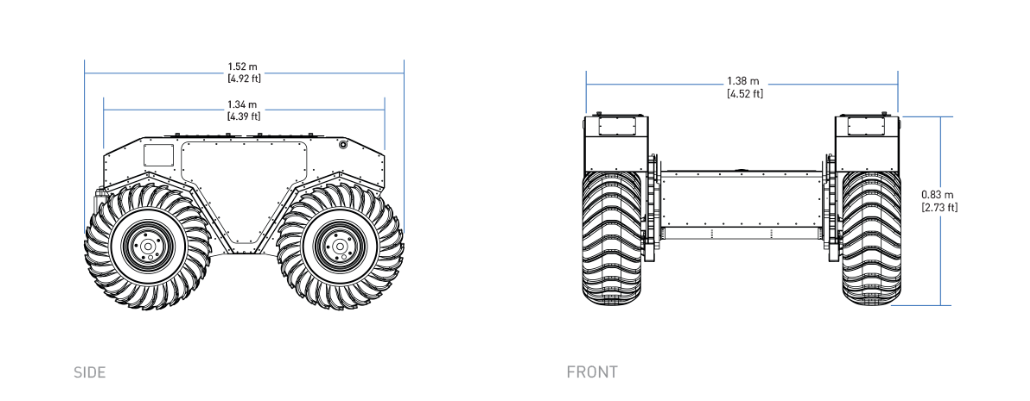
| External Dimensions (L x W x H) | 1.52 X 1.38 X 0.83 metres (4.9' X 4.5' X 2.72') |
| Base Weight | 280 kg (551 lbs) |
| Ground Clearance | 254 mm (10 in) |
| Max Payload | 272 kg (600 lbs) |
| Max Incline | 35 - 45° |
| Max Speed | 18 km/h (11 mph) |
| Suspension | Geometric Passive Articulation |
| Drive Configuration | 4 X 4 Skid Steer |
| Operating Environment | Outdoor |
| Traction | Ø610 mm (24") Argo Turf tire (default) or 300 mm (12") wide Quad Track System (optional) |
| Battery Chemistry | AGM sealed lead-acid (LiFEPO4 optional) |
| Capacity | 105 Ah at 48 V, expandable to 118 Ah at 51.2V with LiFEPO4 option |
| Nominal Run Time | Lead-acid: 2.5 hrs, LiFEPO4: 6 hrs |
| Charge Time | 4 Hours approx |
| User Power | 12 V, 24 V and 48 V Fused at 10 A |
| Control Modes | Remote control, computer controlled velocity commands, indoor/outdoor autonomy packages |
| Feedback Battery | Voltage, motor currents, wheel odometry, control system status, temperature, safety status |
| Communication | Ethernet, USB, Remote Control, Wi-Fi |
| Drivers | Packaged with ROS Noetic (includes RViz, Gazebo support), Matlab API available |
Getting Started
You are ready to go! This section details how to get Warthog into action. To begin, place Warthog "up on blocks", making sure that the wheels are clear of the ground.
For most Warthog setups, there will be an Onboard Computer which is directly connected to the Warthog and an Offboard Computer which is used to control Husky and gather data. These two computers must be set up to communicate with each other.
Onboard Computer Setup
Warthog ships with an Onboard Computer from Clearpath Robotics, which is already installed, connected, and powered. If you need to reinstall the software on it, refer to the Warthog Tutorials.
Powering Up
To power on your Warthog, twist the red power button on the back of Warthog. Once the body lights are flashing red, twist (to reset) all four Stop buttons (if necessary), and press go on the Wireless Stop remote (next section). In a moment, Warthog should go to solid red lights in back, and solid white in front. This indicates that ROS is up on the computer and has established communications with the MCU.
Using the Wireless Stop Remote
Included with the Warthog is a Wireless Stop remote. If for any reason the robot must be halted immediately, press the red STOP button. This will immediately cut power to the robot's motors.
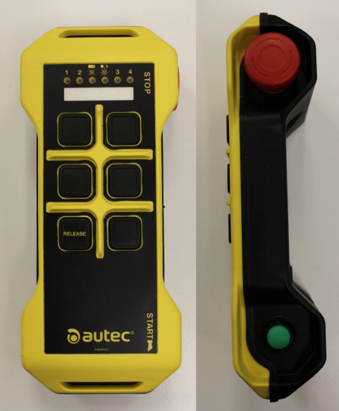
It's capable of engaging a stop remotely. The system is designed to enter a stopped state when the remote is not communicating or loses communication with the base. The Wireless Stop remote operates as follows:
- Pull the red STOP button outwards to disengage it from a stop condition.
- Press and hold the green START button on the right side of the unit until the battery LED indicator above the buttons turns green. If the battery light is red, this means the STOP button is still engaged.
- Press the button labelled RELEASE within three seconds followed by the START button again.
- The battery LED should be blinking green quickly, this indicates the remote is paired with the receiver. To disengage the stop, press START once again.
The battery LED should now be blinking slower, this indicates the remote stop has been disengaged. The corner body lights of the Warthog will change from blinking red to solid red at the rear and white at the front assuming all other safety stop sources have been disengaged. The Warthog is now ready to drive.
If you're not seeing any change in behaviour, please contact our support team.
Using the Stop buttons
Warthog has four Stop buttons located on the four corners of the robot. Pressing any of these buttons will cut power to the motors, just like the STOP button on the Wireless Stop remote. To disengage the stop, simply twist the button in the direction indicated by the arrows.
Whenever you need to perform maintenance on Warthog, we recommend engaging the stop if the robot cannot be fully powered down.
Drivetrain
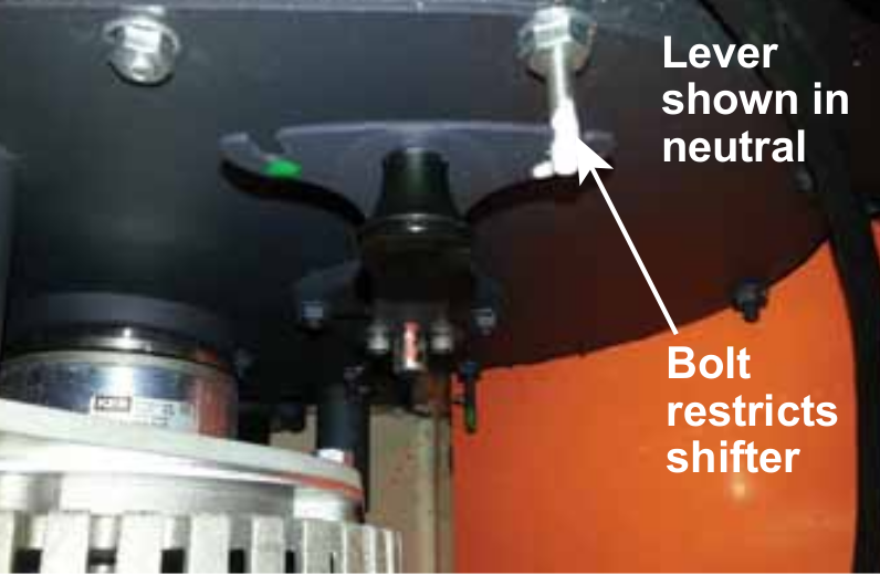
The Warthog has the ability to be put into neutral which is controlled be the four levers (two per side) in the rockers.

Use the bolts to restrict the lever from moving as down when the drivetrain is in neutral. The groove for the neutral position is marked with white and the bolt is also marked. This is shown below.
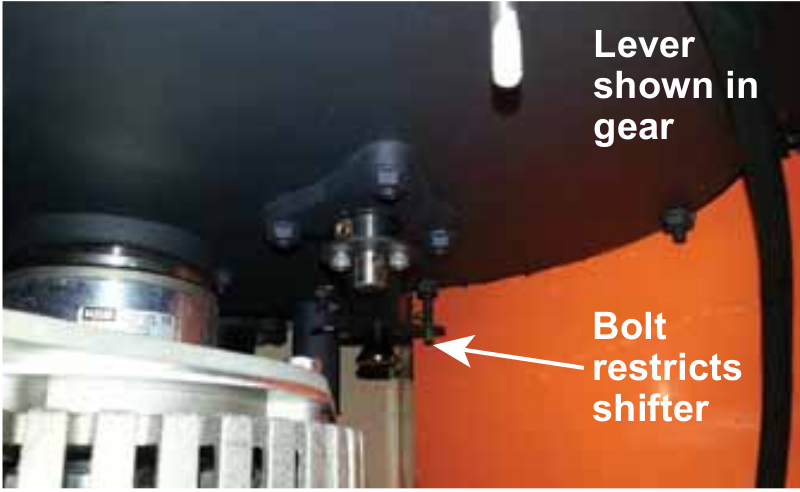
Pull the handle on the lever to move it into gear which can be seen below. Ensure the lever is in the green groove. If the lever is difficult to move, rock the Warthog back and forth. Do not try to force the lever to move.
Using the Futaba Controller
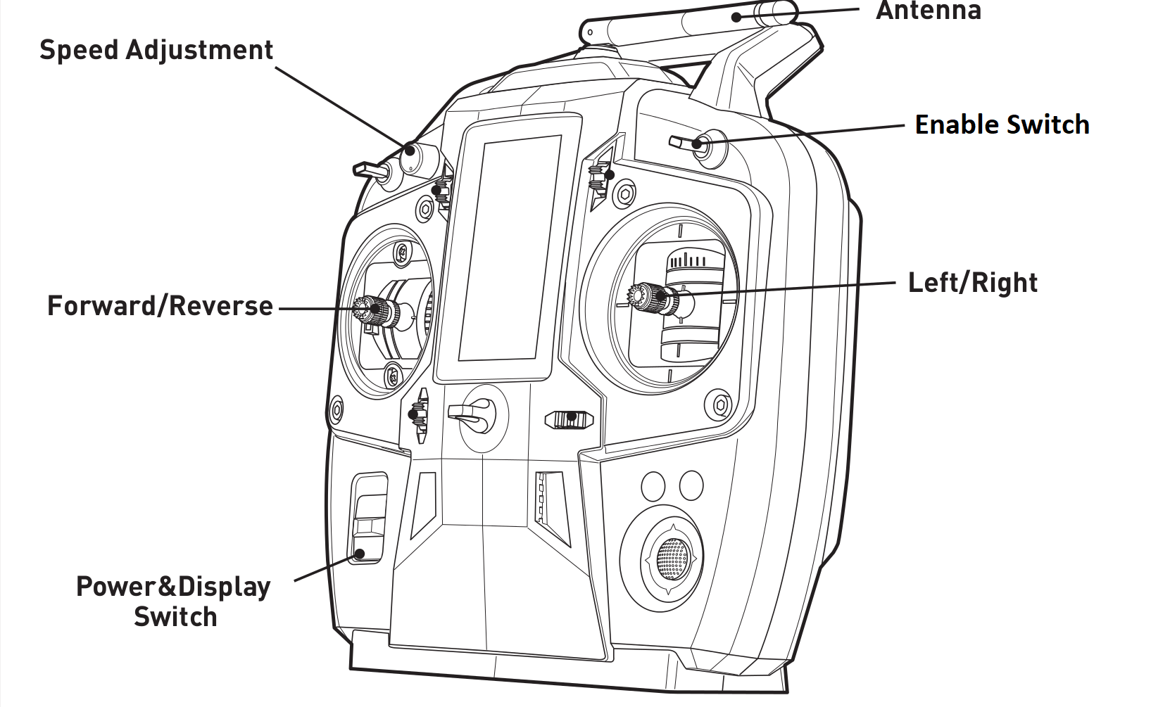
The long range remote control (RC) Futaba radio transmitter can be used to teleoperate the Warthog. To begin, slide the power switch to the ON position which is labelled in the figure below.
The speed adjustment knob should be turned initially all the way to the left while familiarizing yourself with the transmitter and slowly increasing it to get it moving.
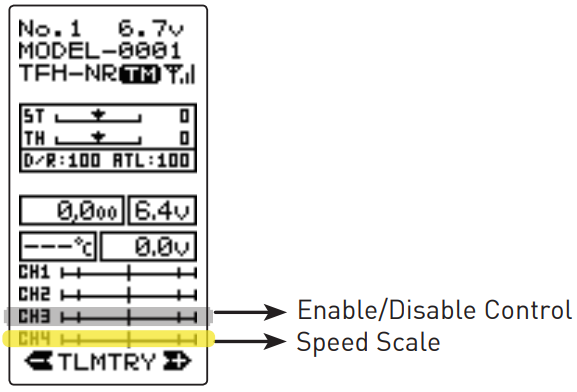
The position of the speed adjustment scale is shown in the figure as CH4. The transmitter needs to be enabled which is done using the Enable Switch. The Enable Switch is a two position spring loaded switch. To enable the RC teleoperation, the switch needs to be held down. If released, the switch returns to the up position to disable the robot. The left joystick is used for the forward and reverse motion of the robot and the right joystick is used for turning.
If the Clearpath Robotics Outdoor Navigation software is installed on the Warthog, the Futaba remote controller (RC) must be turned OFF for autonomous missions to be properly executed by the navigation software.
The Futaba RC will always publish messages to the /rc_teleop/cmd_vel topic when it is ON, and since it has higher priority than the navigation's /cmd_vel, the Warthog will not move if autonomous missions are sent and the RC is still ON.
Network Configuration
To get Warthog connected to your local Wi-Fi network, you must first access the Onboard Computer using a wired connection to the robot. Locate the User Breakout Panel on the rear of the chassis and connect to an Ethernet port with a standard Ethernet cable. See the Warthog Tutorials for details on completing the Wi-Fi setup.
Using ROS
Robot Operating System (ROS) is an extensible framework for controlling and working with robotic systems. Clearpath Robotics recommends using ROS with your robot. If this is your first time using ROS, it is strongly recommended to run through our series of ROS tutorials to learn the basics of ROS.
Safety Considerations
Clearpath Robotics is committed to high standards of safety. Warthog contains several features to protect the safety of users and the integrity of the robot.
Warthog is a powerful, heavy, fast moving robotic platform. Please read the following safety information carefully.
General Warnings
For the safety of yourself and others, always conduct initial experiments and software development with the motors not engaged. Whenever the robot is not being operated and the motors are engaged, keep it in a stop state. Do not ride on the vehicle, it can accelerate and brake quickly.
When starting out, favour slower wheel speeds. Warthog's control loops can accurately maintain velocities as low as 0.1 m/s. Operating at such speeds will give you more time to react if things don't go quite as you expect.
When enabling the system using the GO button on the wireless remote, be sure to stand well back from the Warthog. User code running on the Warthog may still be trying to command the motors, and this can result in sudden and unexpected movement of the vehicle. Be prepared to stop the system again using the wireless remote.
Maneuverability in Water
Before entering the water it is important to ensure that:
- Bilge pumps are functioning properly
- The side panels and top cover are properly fastened down
- All access panels are fastened down
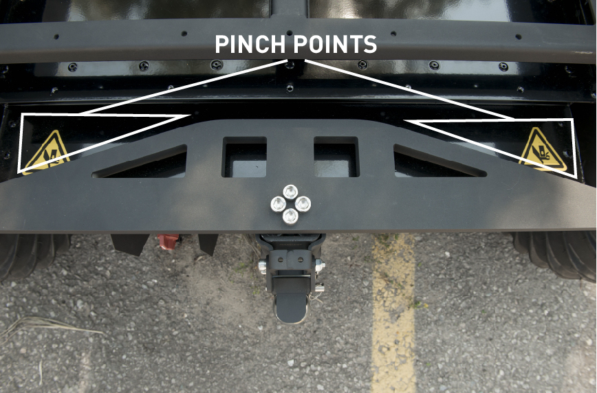
Pinch Points
When operating the Warthog it is important to maintain a safe distance away from the unit. The suspension has the ability to pivot. Do not place fingers anywhere along the suspension link as it can result in injury.
Stop buttons
The Stop system on the Warthog has two major components: The hardwired Stop switches and the Wireless Stop remote.
Hardwired Stop
Pressing down one of the 4 red mushroom Stop buttons around the Warthog will disable power to the motor controller SEVCON devices (Key switch input on PIN 1). This disables the large contactors and also enables the brakes (passive, spring activated when not powered). The status indicator lights around the Warthog will flash red. To reset a Stop button, the top of the button should be twisted until the button pops out again. The GO button on Wireless remote must then pressed. The Warthog is fully enabled once a relay click is heard, and the front lights change to white.
Wireless Stop Remote
To operate the Warthog, the Wireless Stop remote also has to be powered on (by holding the Power button for at least 1 second). The remote STOP button toggles the stop status. It must be pressed once to enable stop, and pressed again to return to a stop reset ready state. The GO button on the remote will then reset the stop condition. Always ensure the STOP button is accessible at all times. Avoid mounting payloads that extend over the rear of Warthog and would occlude the Stop buttons.
Electrical System
The largest electrical safety consideration with the Warthog system is the VBAT connection. As it is pulled straight from the batteries, it may have a voltage of 48 V (depleted) to 62 V (Charging) and can be used to power large external devices. This voltage can cause electrical shock if directly contacted, and is fused internally with an inline fuse at 10 A. In general, take care to connect or disconnect devices preferably only when the entire system is powered off via the external switch on the rear (main power switch). Take note that triggering a stop condition only disables voltage to the motor controller SEVCON drivers and motors, not the rest of the system which includes the connectors. The labelled status LEDs on the user panels indicate status of the system voltages. If a LED is not lit, then it's most likely that a system fuse has blown. Contacting Clearpath support is the best option. To ensure safety, please also observe the following precautions:
- Do not tamper with the battery terminals or wiring.
- Consult Clearpath Robotics support if you need to service the battery pack.
- Do not lay tools or other objects on top of the battery.
- Do not move the robot while charging the battery.
- Charge the battery only with the charger provided by Clearpath Robotics.
- Please dispose of the batteries properly, or return the batteries to Clearpath Robotics to do so.
Lifting and Transport
For the safety of users and to maximize the lifetime of Warthog, please observe the following when manually transporting the robot:
- Ensure that Warthog's stop mode is engaged when transporting short distances and powered off when transporting longer distances.
- Do not push the robot at more than 0.5 m/s (1.6 ft/s) or damage to the motor controls may occur.
Performance Considerations
Included in Warthog are native software checks and limits to protect the robot.
However, it is recommended to monitor the system's status during usage with the /status and /diagnostics topics.
These topics provide useful information regarding voltages, currents, temperatures and general health of the system.
Recommended Safe Work Procedures
Common Safe Work Procedures
Clearpath Robotics recommends the following procedures be followed to reduce the likelihood of harm.
- Maintain a safe distance of at least 10 m from the robot whenever possible.
- Never assume that the robot can be reliably stopped on command.
- Assert a stop using the remote stop device (if present) before approaching the robot.
- Never place the remote stop device (if present) on or inside the robot.
- Always be vigilant around the robot, even when a stop is asserted.
- Perform no maintenance or troubleshooting on the robot without training and familiarisation.
- Follow electrical safety best practices when working with electrical systems and components.
- Disconnect battery using main disconnect of the robot before working inside robot.
- Wear personal protective equipment including high-visibility clothing, head and eye protection while operating, observing or working on the robot.
- Never climb on or ride the robot.
- Never lie on the ground under or near the robot.
- Avoid operating the robot on slopes and grades.
- Never stand downhill of the robot.
- Operate the robot at the lowest speed possible.
- Never attempt to defeat a safety function for any reason.
- Chock the robot's wheels when the robot will be stationary for more than a few seconds.
- Never work on the robot while it is on a slope.
- Replace fuses only with identical product from specified manufacturer.
- Discontinue use and contact Clearpath Robotics support at the first sign of strange robot behaviour.
- Keep tools and loose parts away from electrical components and out of the robot's bays.
- Check the functionality of stop systems on a regular basis, including before and after each use.
Warthog-Specific Safe Work Procedures
- Keep hands and fingers away from the suspension linkage components at the rear of the robot.
- Never approach the robot while it is operating in water.
- When working on or around the robot always disconnect the motors using the drivetrain levers as described in the user manual.
- Never disconnect the robot motors using drivetrain levers when on a slope.
- Do not attempt to move or operate the robot while charging the batteries.
Support
Clearpath is committed to your success. Please get in touch with us and we will do our best to get you rolling again quickly: <support@clearpathrobotics.com>.
To get in touch with a salesperson regarding Clearpath Robotics products, please email <research-sales@clearpathrobotics.com>.
If you have an issue that is specifically about ROS and is something which may be of interest to the broader community, consider asking it on Robotics Stack Exchange. If you do not get a satisfactory response, please ping us and include a link to your question as posted there. If appropriate, we will answer on Robotics Stack Exchange for the benefit of the community.