Dingo Integration
To attach custom hardware to Dingo, you will have to take care of mechanical mounting, electrical supply, and software integration. This guide aims to equip you with respect to these challenges.
Mechanical Mounting
When determining mechanical mounting, you have two options, both of which are described below.
- the "Standard" mounting pattern on Dingo's trough cover
- the "PACS™" mounting system and associated kits
Mechanical, Standard
A standard Dingo is delivered with an 80 mm square mounting pattern of M5 threaded holes on Dingo's trough cover as shown in Exterior Features, which can be used for attaching external payloads. The mounting holes come with M5 screws pre-installed. You may mount your hardware directly onto the trough cover or you may design and mount a new plate to the trough cover and secure it to the trough cover using M5 screws.
Mechanical, PACS™
PACS™ is a Clearpath Robotics standard. We add a grid of M5×0.8 holes onto the top plate of the robot. This grid of holes has a 80 mm X 80 mm spacing. You can create your own brackets to interface with these holes, or can use an existing Clearpath Robotics designed bracket.
Our Sensors and Accessories pages indicate the required bracket for the particular attachment.
Refer to the following pages for Dingo brackets that can simplify your integration.
Electrical Integration
Except for bus-powered USB cameras, most payloads have separate leads for power and data.
Data Connections
Data connections may be brought through the openings in the trough cover and connected directly to the internal computer.
Dingo's internal computer options support USB3 and Ethernet connectivity. In addition, the PCIe Gen3 x16 slot may be used to supply a GPU or other attachements, as necessary. Additionally, the internal mounting area may be used for an Ethernet switch, when attaching multiple Ethernet payloads, or for a PoE power injector as required.
Connector Summary
The Dingo MCU board provides a number of connections for power, relays, auxiliary inputs and auxiliary outputs. These are summarized in the following table and described in more detail in the following sections.
| MCU board label | MCU board connector | Mating connector | Crimp terminals | Crimping tool |
|---|---|---|---|---|
| PWR1, PWR2 | Dingo 1.0: Molex 0039301040 Dingo 1.5: Molex 0039302040 | Dingo 1.0: Molex 0039012040 Dingo 1.5: Molex 0039014041 | Molex 0507528200 (AWG 20-22) or Molex 0503518100 (AWG 22-28) | Molex 2002184900 |
| VBAT | Molex 768250002 | Molex 1700010102 | Molex 0507528200 (AWG 20-22) or Molex 0503518100 (AWG 22-28) | Molex 2002184900 |
| INPUTS | TE 3-794682-8 | TE 794617-8 | TE 1-794610-1 (AWG 20-24) or TE 1-794611-1 (AWG 26-30) | TE 91391-1 |
| SW_IN | TE 2-1445094-2 | TE 1445022-2 | TE 1-794610-1 (AWG 20-24) or TE 1-794611-1 (AWG 26-30) | TE 91391-1 |
| AUX1, AUX2, AUX3 | TE 3-794682-4 | TE 794617-4 | TE 1-794610-1 (AWG 20-24) or TE 1-794611-1 (AWG 26-30) | TE 91391-1 |
| RELAY | TE 4-794682-0 | TE 1-794616-0 | TE 1-794610-1 (AWG 20-24) or TE 1-794611-1 (AWG 26-30) | TE 91391-1 |
| FAN | Molex 0533750210 | Molex 0511630200 | Molex 0507528200 (AWG 20-22) or Molex 0503518100 (AWG 22-28) | Molex 2002184900 |
| ESTOP | Molex 053370610 | Molex 0511630600 | Molex 0507528200 (AWG 20-22) or Molex 0503518100 (AWG 22-28) | Molex 2002184900 |
User Power Connections
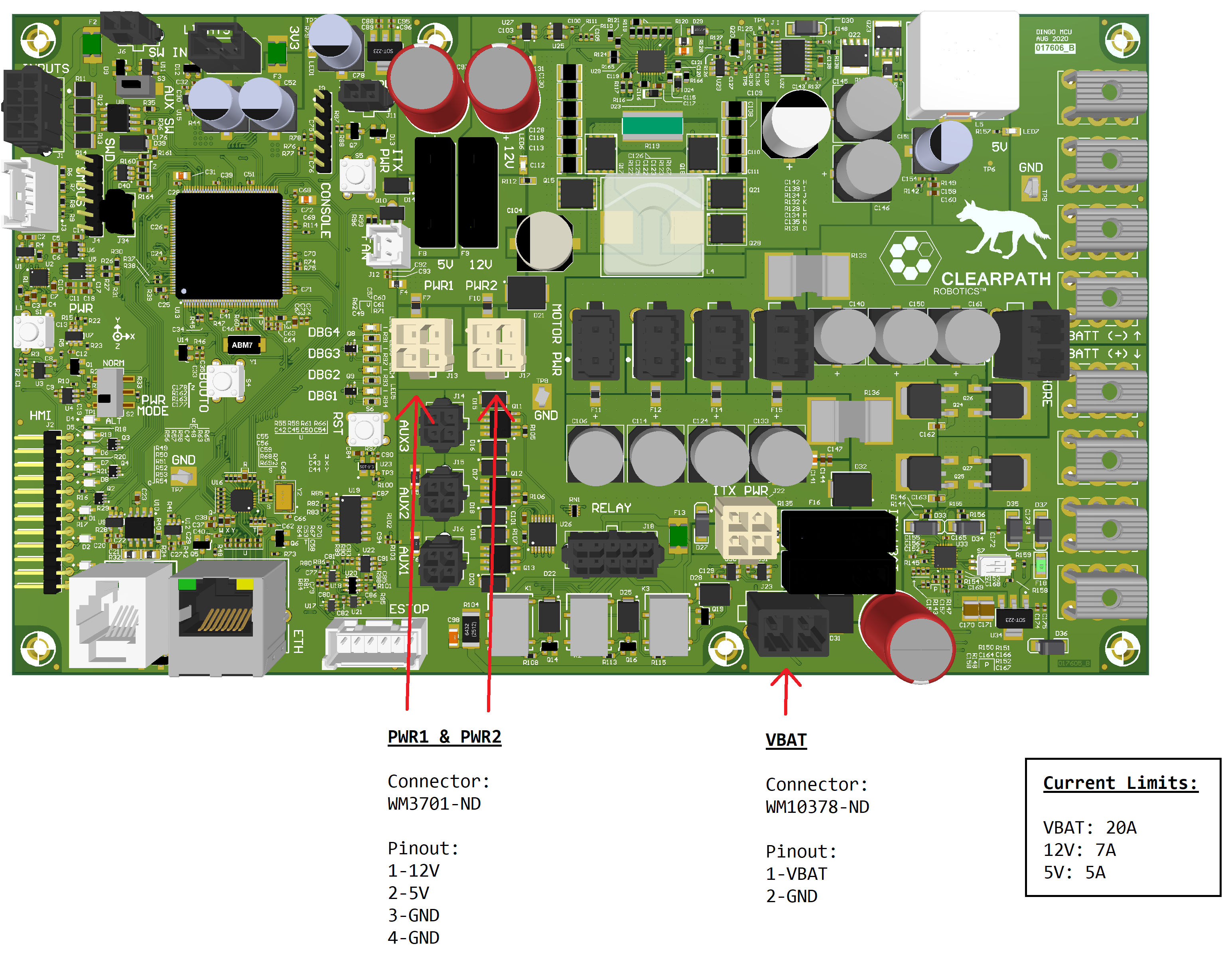
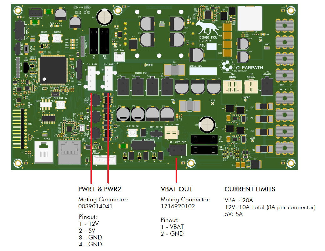
The following are available as user power: unregulated battery power (see VBAT), regulated 12 V power (see PWR1 and PWR2), and regulated 5 V power (see PWR1 and PWR2).
Similar to the data connections, the power leads may be brought through the trough cover and connected to the user power. Remove the front trough cover by removing four flathead screws and locate the appropriate power connector on the MCU board. Refer to the figure below for the location of the user power connectors. Route the power from the MCU board to the appropriate location, either to the internal payload modules or through the openings in the trough cover to the topside payload.
- Dingo 1.0
- Dingo 1.5
AUX Inputs
The Dingo MCU includes an 8-pin INPUTS connector and a 2-pin SW_IN connector that allow the user to provide inputs to the system.
The user can then subscribe to these inputs on the /mcu/aux_inputs ROS topic.
The AUX inputs are mapped to the ROS message bits as follows:
- IN1: bit 0
- IN2: bit 1
- IN3: bit 2
Electrically, the INPUTS connector is used for IN1 and IN2, with pin mapping as outlined below.
Note that each of the two inputs can be 12 V or 24 V inputs, with a shared return path.
The inputs have opto-electrical isolation.
- 1: 12 V power (for external input circuit, if needed)
- 2: IN1 return
- 3: GND (for external input circuit, if needed)
- 4: IN2 return
- 5: IN1 12 V input
- 6: IN1 24 V input
- 7: IN2 12 V input
- 8: IN2 24 V input
Electrically, the SW_IN connector is used for IN3, with pin mapping as outlined below.
This is intended to be a 'switch' input and it generates a 100 ms pulse to the microcontroller when asserted.
- 1: 3.3 V input (IN3)
- 2: GND
AUX Outputs and Relay
The Dingo MCU includes three user-controlled outputs (AUX1, AUX2, AUX3), that can be controlled by publishing to the /mcu/aux_outputs ROS topic.
To enable the AUX outputs, simply publish a single message with the appropriate bits set to 1 to turn the output on and 0 to turn it off.
The state does not persist meaning new commands will need to keep the bit enabled as well.
The AUX outputs are mapped to the ROS message bits as follows:
- AUX1: bit 0
- AUX2: bit 1
- AUX3: bit 2
For example, to disable all AUX outputs:
rostopic pub /mcu/aux_output std_msgs/UInt8 "data: 0"
For example, to enable all AUX outputs:
rostopic pub /mcu/aux_output std_msgs/UInt8 "data: 7"
For example, to enable just the AUX3 output:
rostopic pub /mcu/aux_output std_msgs/UInt8 "data: 4"
Each of the AUX outputs is a 4-pin connector with pin mapping as outlined below.
AUX1 Pin Mapping
- 1: VSYS (shore power or battery power) with 5 A fuse
- 2: VSYS (shore power or battery power) with 5 A fuse
- 3: GND
- 4: GND
AUX2 Pin Mapping
- 1: 12 V with 5 A fuse
- 2: 12 V with 5 A fuse
- 3: GND
- 4: GND
AUX3 Pin Mapping
- 1: 5 V with 5 A fuse
- 2: 5 V with 5 A fuse
- 3: GND
- 4: GND
Relays
In addition to the AUX output connectors, publishing to /mcu/aux_outputs also
controls the AUX relays. These relays are available through the 10-pin
connector on the MCU labelled RELAY with pin mapping:
- 1 and 6: 12 V with 2 A fuse
- 5 and 10: GND
- 2 and 7: AUX1 relay closed with aux_outputs bit 0 is '1'
- 3 and 8: AUX2 relay closed with aux_outputs bit 1 is '1'
- 4 and 9: AUX3 relay closed with aux_outputs bit 2 is '1'
Optional Fan
While a fan is not included by default with Dingo, a fan may be integrated into the system.
Electrically, connect a 12 V 2-pin fan to the MCU connector labelled FAN using a mating connector.
The pins should be connected as follows:
- 1: 12 V @ 500mA max
- 2: GND
Then, the use can publish a ROS message to the /mcu/fans topic to control the fan.
Optional External Motion Stop
In addition to the built-in Motion Stop button, an external motion-stop button can be added that has similar functionality.
Electrically, the external motion-stop button can be connected to the 6-pin MCU connector labelled ESTOP using a mating connector.
The six pins should be connected as follows:
- 1-2: to an external "normally closed" motion-stop breakout button:
- press to engage the motion stop
- twist and release the external motion stop button to clear the motion-stop
- to re-enable the motors, the Motion Stop Button on the HMI panel must be pressed
- 3-4: short these pins to indicate that external motion-stop is selected
- 5-6: short these pins to indicate that external motion-stop is present
MCU Debug LEDs
The Dingo MCU PCBA comes equipped with four LEDs controlled by Dingo firmware for debugging. If the system is working properly, these LEDs functions as follows:
- DBG1: toggles every 500 ms when main loop on MCU is running
- DBG2: on if MCU connected to ROS on computer; else false (same as COMMS LED on HMI)
- DBG3: toggles when MCU is relaying messages from CAN bus to computer
- DBG4: toggles when MCU is relaying messages from computer to CAN bus
Software Integration
ROS has a large ecosystem of sensor drivers, some of which include pre-made URDF descriptions and even simulation configurations. Refer to Sensors supported by ROS.
For the best experience, consider purchasing supported accessories from Clearpath Robotics for your robot, which will include simulation, visualization, and driver support.
Refer to the following for more details:
Support
Clearpath is committed to your success. Please get in touch with us and we will do our best to get you rolling again quickly: support@clearpathrobotics.com.
To get in touch with a salesperson regarding Clearpath Robotics products, please email research-sales@clearpathrobotics.com.
If you have an issue that is specifically about ROS and is something which may be of interest to the broader community, consider asking it on https://robotics.stackexchange.com. If you do not get a satisfactory response, please ping us and include a link to your question as posted there. If appropriate, we will answer in the ROS Answers context for the benefit of the community.