Ridgeback User Manual
Introduction
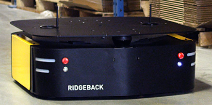
Clearpath Robotics Ridgeback is a rugged, indoor omnidirectional platform designed to move manipulators and other heavy payloads with ease and precision. This manual contains information about the setup, safe operation, and maintenance of your Ridgeback unmanned omnidirectional platform.
Mobile robots are inherently hazardous. It is the responsibility of the deployer to ensure that all personnel that may come into contact with the system are trained properly. It is also the responsibility of the deployer to understand the hazards presented and to ensure sufficient safeguards or other mitigations are in place. Refer to the Safety section of this manual for further details.
Shipment Contents
Your Ridgeback shipment contains the following:
- Ridgeback Omnidirectional Robotic Platform, including computer, forward-facing LIDAR, batteries, and integrated battery charger
- One Sony PS4 Bluetooth controller
- One Ridgeback quick start guide
If you elected to purchase standard payload modules or custom integration services with Ridgeback, then additional equipment will be included per your specific configuration, plus further documentation as required.
Hardware Overview
System Architecture
Ridgeback is built around a computer running Ubuntu (Intel-based computer or Jetson developer kit), paired with a 32-bit microcontroller MCU. The MCU handles I/O, power supply monitoring, and motor control, as well as supplying data from the integrated IMU. The communication channel between the MCU and computer is a Gigabit Ethernet connection.
Exterior Features
The exterior of Ridgeback is shown below and includes:
- Stop, Reset, and Power buttons
- Body Lights
- User Bay
- Payload Integration Plate

Buttons
There are four push buttons located on the back of the Ridgeback: the two red mushroom Stop buttons, the Stop Reset button below the left rear Stop button, and the Power ON/OFF button below the rear right Stop button. On the front of the robot, there are another two red mushroom Stop buttons. These buttons are described further in the table below.
| Button | Description |
|---|---|
| Power ON/OFF | Turns Ridgeback on or off. Note that the power button is a soft, momentary switch: to shut Ridgeback down, press and release it, and when the Onboard Computer has completed a safe power-down, the robot itself will also power-down. |
| 4X Stop | Stops Ridgeback by placing the four integrated motor drivers into an electrical reset condition. This is intended as a backup option for immobilizing Ridgeback when autonomy software malfunctions or commands unintended motion. The Stop buttons have a mechanical latch, which can be released by twisting the latched button. If you have a wireless Stop pendant, or other stop-asserting hardware you would like to integrate with Ridgeback, a breakout header is supplied on the main microcontroller PCB. |
| Stop Reset | Clears the electrically-enforced stop latch, allowing Ridgeback to run again after it has been stopped via one of the Stop buttons. Note that the mushroom button's mechanical latch must be cleared before the electrical reset can have any effect. |
Body Lights
Ridgeback includes eight RGB body lights, stacked in a pair on each corner of the chassis. These lights express system status according to the table below, but in the absence of one of the low-level conditions, they can be commanded from ROS to display indications from autonomy or other higher-level software. See http://wiki.ros.org/ridgeback_base for information on commanding the body lights.
| Front Lights | Rear Lights | System State |
|---|---|---|
| Solid red | Solid red | The MCU is not in contact with the computer. That is, the rosserial connection is not active. This condition will be seen briefly on startup while Ridgeback's computer is booting up. If it persists, or is seen after initialization, either the base node on the computer has crashed, the network switch has failed, or a serious MCU error has occurred. If you suspect one of these conditions, please contact support. |
| Flashing red | Flashing red | Stop mode is engaged. To disengage, twist the mushroom buttons to ensure that they are unlatched, and check any external stop hardware, if present. |
| Flashing orange | Flashing orange | A system fault has been detected, typically the motor drivers. Refer to logs or diagnostics for details. |
| Pulsing orange | Pulsing orange | Battery is low. Connect Ridgeback to the charger. |
| Alternating red/off | Alternating red/orange | All stops are mechanically cleared but still electrically latched. Press the Stop Reset button to enable full operation. |
| Pulsing green | Pulsing green | Charger is connected, Ridgeback's battery is charging. Note that the battery can also be charged with the platform off. This indication will only be seen if the charger is connected while Ridgeback is powered up. |
| Solid green | Solid green | Charger is connected and Ridgeback is charged fully. |
| Solid white | Solid red | Normal operation; ready to drive. The intensity of the lights will increase slightly when actually in motion. This is the status which may be overridden by publishing your own light patterns to the /cmd_lights ROS topic. |
User Bay
The User Bay provides access to the User Power Panel, as well as USB and Ethernet ports, and additional space for stowing user equipment. The electrical panel can be used to power your payloads, with further details available in Electrical Integration. The USB3 ports are connected directly to the Onboard Computer, and the Ethernet ports connect to the onboard network switch. To connect a device to the onboard network, it is suggested to give it a static IP in the 192.168.131.x/24 subnet and this cannot be changed since the MCU is statically set to 192.168.131.2 and expects the computer to be at 192.168.131.1. Avoid IPs in use by the following pre-existing devices:
| IP Address | Device Assignment |
|---|---|
| 192.168.131.1 | Onboard Computer (both ports, br0 network interface) |
| 192.168.131.2 | Ethernet-connected MCU |
| 192.168.131.20 | Front-facing LIDAR |
| 192.168.131.21 | Rear-facing LIDAR (if present) |
See Standard IP Addresses for a full list of common IP addresses.
Payload Integration Plate
The Payload Integration Plate provides a robust foundation for mounting payload structures such as UR5/UR10 manipulation arms or any other combination of sensors and manipulators. For more information and guidance on mounting payload structures on top of Ridgeback, please refer to Mechanical Integration.
Orientation References
The reference frame used by all Clearpath Robotics ground robots is based on ISO 8855.
When commanded with a positive translational velocity (forward), wheels travel in the positive x-direction. The direction of the axes differs from those used for roll, pitch, and yaw in aircraft, and care should be taken to ensure that data is interpreted correctly.
System Specifications
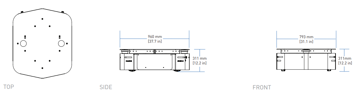
| Specification | Measurement |
|---|---|
| Dimension, Length | 960 mm |
| Dimension, Width | 793 mm |
| Dimension, Height | 311 mm † |
| Ground Clearance | 18 mm |
| Maximum Payload | 100 kg |
| Speed, Maximum | 1.1 m/s |
| Operating Environment | Indoor |
| Operating Time | 15 hours with max payload (24 V 100 Ah) |
| Battery Chemistry | Marine Grade AGM Sealed Lead Acid |
| Charge Time | 8 hours |
| User Power | 20 A @ VBAT (24 V), 5 A @ 12 V, 5 A @ 5 V |
| Power | 800 W Typical Use, Shore Power Available |
| Control Modes | Kinematic control (forward, sideways, rotation), individual wheel velocities |
| Communication | Ethernet, USB 3.0, RS232 |
| Internal Sensing | Battery Status, Wheel Odometry, Motor Currents, Onboard IMU |
† The height of the Ridgeback was increased by 15 mm starting with the robot with serial number R100-0111. Older Ridgebacks measure 296 mm high.
Getting Started
You are ready to go! This section details how to get Ridgeback into action. If you are just opening up the shipping crate, you can unfold the ramp, and remove the ratchet straps which secure Ridgeback during shipping.
To begin, place Ridgeback "up on blocks" as described in the Safety section, making sure that the wheels are clear of the ground.
Onboard Computer Setup
A standard Ridgeback ships with an integrated Onboard Computer that is directly connected to the Ridgeback MCU. Most users will also make use of an Offboard Computer, which is used to control Ridgeback and gather data. These two computers must be set up to communicate with each other. Details on the Offboard Computer setup can be found in Ridgeback Tutorials.
Powering Up
Press the power button on the back of Ridgeback. Once the body lights are flashing red, clear the all Stop buttons (if necessary), and press the blinking red Stop Reset button. In a moment, the platform should go to solid red lights in back, and solid white in front.
Network Configuration
To get Ridgeback connected to your local Wi-Fi network, you must first access the Onboard Computer using a wired connection to the robot. Open the User Bay, then connect to one of the network ports with a standard Ethernet cable. Then, see Ridgeback Tutorials for details on completing the networking setup.
Connecting and Using the Controller
To use your controller, it must be paired with your Ridgeback and powered on. For a standard Ridgeback with the Onboard Computer from Clearpath Robotics, the controller is already paired with your Ridgeback. If your controller has become unpaired or if you wish to pair a new controller, following the instructions in the Ridgeback Tutorials.
To teleoperate Ridgeback, first clear the motion-stop.
Then, power on the controller by pressing the PS button on the controller.
Once the blue LED on the top of the controller goes solid, you are paired and ready to drive.
Hold the L1 trigger button (deadman switch) and push the left thumbstick forward to drive the Ridgeback. See the figure below for the Sony PS4 controls layout. If you are not seeing any action, refer to Support to get in touch with support.

Using ROS
Robot Operating System (ROS) is an extensible framework for controlling and working with robotic systems. Clearpath Robotics recommends using ROS with your robot. If this is your first time using ROS, it is strongly recommended to run through our series of ROS tutorials to learn the basics of ROS.
Battery Charging
Ridgeback uses two 8A31DTM Group-31 lead-acid (PbSO4) deep-cycle AGM batteries mounted low in the chassis. They provide an output of 24 VDC (nominal) and 100 Ah of capacity.
When finished with the Ridgeback, press and release the power button to power it off.
Ridgeback has an internal charger. All that is required to charge Ridgeback is to open the User Bay access panel, locate the charger power cord and plug it into any 85-270 VAC 50/60Hz mains outlet. The robot can be turned "on", though we recommend against driving the robot when the battery is charging.
The battery pack is rugged and designed for the environments into which Ridgeback may be deployed. However, please take note of the following:
- The batteries and robot must not be stored or operated above 50 ◦C or below -20 ◦C.
- If the robot is to be stored for any length of time it should be in a cool, dry location. The batteries should be fully charged and periodically maintained at full charge to ensure a long service life. Ridgeback should not be stored with a low state of charge nor for extended periods of time without top-up charging. The batteries may suffer from "sulfation" which reduces their capacity and lifetime.
- Do not allow the batteries to reach a depth of discharge of 80%.
- The batteries must not be punctured or disassembled.
- The batteries should be disposed of pursuant to your local regulations regarding electrical and/or hazardous waste.
The integrated Ridgeback charger will fully charge the internal lead-acid battery in a few hours. The charger will time out after 12 hours, so be sure to power cycle (by unplugging and re-plugging) the charger on a daily basis. Allow the battery to warm up to at least 10°C before charging.
When the battery is running low on charge, the corner lights will start to flash yellow. This is your indication that the Ridgeback should be plugged in to charge soon.
Please contact Clearpath Robotics for additional information about Ridgeback's batteries or for information about purchasing additional batteries.
Safety Considerations
Clearpath Robotics is committed to high standards of safety. Ridgeback contains several features to protect the safety of users and the integrity of the robot.
Ridgeback is a powerful, heavy, fast moving robotic platform. Please read the following notices carefully.
General Warnings
Ridgeback is a rugged and high-performance vehicle. For the safety of yourself and others, always conduct initial experiments and software development with the vehicle raised off the ground. Place a wooden crate, a set of sawhorses, a sturdy storage tub, or any other solid flat structure having a height greater than 150 mm (6 inches) under Ridgeback to keep the wheels clear of the ground ("up on blocks").
When starting out, favour slower wheel speeds. Ridgeback's control loops can accurately maintain velocities as low as 0.1 m/s. Operating at such speeds will give you more time to react if things don't go quite as you expect.
Stop Buttons
Ridgeback has four red Stop buttons, two on the front and two on the back. To engage Stop Mode, press any of the four Stop buttons once; you should see that all four corner LEDs are flashing red. To disengage Stop Mode, pull any engaged Stop buttons to release them, then press the Stop Reset button located below the rear-left Stop button; all corner LEDs should return to their original values.
When in Stop mode the Ridgeback will not drive. The commands received during stop are not buffered; Ridgeback will always act on the latest commands received. This means that if motion commands are discontinued before the Stop button is released, the Ridgeback will not move. If the commands are continued, Ridgeback will move at the speed commanded once the Stop is released.
Always ensure the Stop buttons are accessible at all times. Avoid mounting payloads that extend over the front or rear of Ridgeback and would occlude the Stop buttons.
Note that the Ridgeback MCU board includes a breakout to allow an external motion-stop button/switch to be integrated by the end user, which could be used to engage/disengage Stop Mode. See Optional External Motion Stop for details on adding an external motion-stop button/switch.
Electrical System
Ridgeback is powered by two lead-acid (PbSO4) deep-cycle AGM batteries that are capable of delivering over 2000 W for short durations. This gives Ridgeback's motors their great performance; however, it is also enough power to cause severe bodily harm. Always use caution when operating Ridgeback to avoid personal injury or property damage. To ensure safety, please observe the following precautions:
- Do not tamper with the battery terminals or wiring.
- Do not tamper with the fuse panel, except to check and change the fuses, and to connect and disconnect the battery plug.
- Always replace fuses with the same type and rating to ensure continued protection against risk of fires.
- Consult Clearpath Robotics Support if you need to service the batteries.
- Do not lay tools or other objects on top of the batteries.
- Do not move the robot while charging the batteries.
- Charge the battery only with the integrated charger installed by Clearpath Robotics.
- Please dispose of the batteries properly or return them to Clearpath Robotics to do so.
Lifting and Transport
- Ensure that Ridgeback's Stop Mode is engaged when transporting short distances and powered off when transporting longer distances.
- Do not push the robot at more than 0.5 m/s (1.6 ft/s) or damage to the motor controls may occur.
Performance Considerations
Included in Ridgeback are native software checks and limits to protect the robot.
However, it is recommended to monitor the system's status during usage with the /status and /diagnostics topics.
These topics provide useful information regarding voltages, currents, temperatures and general health of the system.
Recommended Safe Work Procedures
Clearpath Robotics recommends the following procedures be followed to reduce the likelihood of harm.
- Maintain a safe distance of at least 10 m from the robot whenever possible.
- Never assume that the robot can be reliably stopped on command.
- Assert a stop using the remote stop device (if present) before approaching the robot.
- Never place the remote stop device (if present) on or inside the robot.
- Always be vigilant around the robot, even when a stop is asserted.
- Perform no maintenance or troubleshooting on the robot without training and familiarisation.
- Follow electrical safety best practices when working with electrical systems and components.
- Disconnect battery using main disconnect of the robot before working inside robot.
- Wear personal protective equipment including high-visibility clothing, head and eye protection while operating, observing or working on the robot.
- Never climb on or ride the robot.
- Never lie on the ground under or near the robot.
- Avoid operating the robot on slopes and grades.
- Never stand downhill of the robot.
- Operate the robot at the lowest speed possible.
- Never attempt to defeat a safety function for any reason.
- Chock the robot's wheels when the robot will be stationary for more than a few seconds.
- Never work on the robot while it is on a slope.
- Replace fuses only with identical product from specified manufacturer.
- Discontinue use and contact Clearpath Robotics support at the first sign of strange robot behaviour.
- Keep tools and loose parts away from electrical components and out of the robot's bays.
- Check the functionality of stop systems on a regular basis, including before and after each use.
Support
Clearpath is committed to your success. Please get in touch with us and we will do our best to get you rolling again quickly: <support@clearpathrobotics.com>.
To get in touch with a salesperson regarding Clearpath Robotics products, please email <research-sales@clearpathrobotics.com>.
If you have an issue that is specifically about ROS and is something which may be of interest to the broader community, consider asking it on Robotics Stack Exchange. If you do not get a satisfactory response, please ping us and include a link to your question as posted there. If appropriate, we will answer on Robotics Stack Exchange for the benefit of the community.