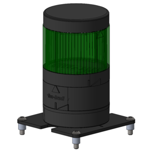
Stack Light
| Description | CPR Item |
|---|---|
| PACS™ kit, including mounting, controls base, and top cap | 027220 |
| Kit, controls base and top cap | 020711 |
| Mounting adapter | 020710 |
| Light Module, Green | 020714 |
| Light Module, Red | 020715 |
| Light Module, Amber | 020716 |
| Light Module, Blue | 020717 |
| Light Module, White | 020718 |
| Light Module, Yellow | 020719 |
| Light Module, Magenta | 020720 |
Pinout
| Pin | Description | Voltage |
|---|---|---|
| COM | Ground | GND |
| 1 | Channel 1, lowest module in the stack | +24 VDC |
| 2 | channel 2 | +24 VDC |
| 3 | channel 3 | +24 VDC |
| 4 | channel 4 | +24 VDC |
| 5 | channel 5 | +24 VDC |
| 6 | channel 6 | +24 VDC |
| 7 | channel 7, highest possible module | +24 VDC |
Hardware Build
Parts List
The PACS™ kit for a stack light includes:
| ID | Description | CPR item | Quantity |
|---|---|---|---|
| 1 | Plate—80 X 80, Attachment Interface | 026914 | 1 |
| 2 | Stack Light Module, Mounting Adapter—Surface Mount | 020710 | 1 |
| 3A and 3B | Bundle, Stack Light Module, Controls Base and Top Cap | 020711 | 1 |
| 4 | Screw, Cap, Socket Head—M4×0.7 X 16, Stainless Steel | 023128 | 2 |
| 5 | Nut, Hex, Lock, Polymer Insert—M4×0.7 X 5, Stainless Steel | 019899 | 2 |
| 6 | Spacer, Round—Ø5.3 X Ø8 X 7, Aluminum Alloy | 026612 | 4 |
| 7 | Screw, Cap, Round Head—M5×0.8 X 16, Stainless Steel | 023257 | 4 |
note
Light Modules are not included in the PACS™ parts list since the configuration of modules depends on your specific integration. Refer to the listed Light Modules at the top of this page for common modules. Refer to this catalog for all available modules and parts, including strobing lights, and buzzers.
Instructions
- Mount the Mounting Adapter (ID 2) to the attachment-plate (ID 1) using the M4 screws (ID 4) and nuts (ID 5). Refer to the attachment-plate's drawing notes for what holes to use for mounting the stack light.
- Place the Controls Base (ID 3A) onto the assembly and twist 10° clockwise to lock it in place.
- Make and connect a cable for controlling the stack light's modules. Refer to the Pinout Section above for details.
- Mount this assembly onto your robot, using the included spacers (ID 6) and screws (ID 7).
- Add light modules onto the assembly and twist 10° clockwise to lock them in place. This locking connection creates an IP65 weatherproof seal, and completes the electrical connection to the Controls Base.
- Place the Top Cap (ID 3B) onto the assembly and twist 10° to lock it in place.