Jetson Nano Hardware in Jackal
Installation
This page outlines the steps for installing the Nano hardware in Jackal. See also the instructions for installing the Jetson software.
Step 1: Remove Mini-ITX Computer
Skip this step if you don't have an existing computer.
If you have a Mini-ITX computer installed it will need to be removed. With the computer tray open locate each of the cables connected to the motherboard and hard drive. Remove the power, power switch, USB and SATA cables. The two cable ties can be cut to completely remove the power and SATA cables. The two antenna cables are connected underneath. Keep this in mind for the next steps.

Disconnecting cables Remove the 4 hex screws from the motherboard using a 2.5 mm wrench. Gently lift it out disconnecting the antenna connectors as you do so.
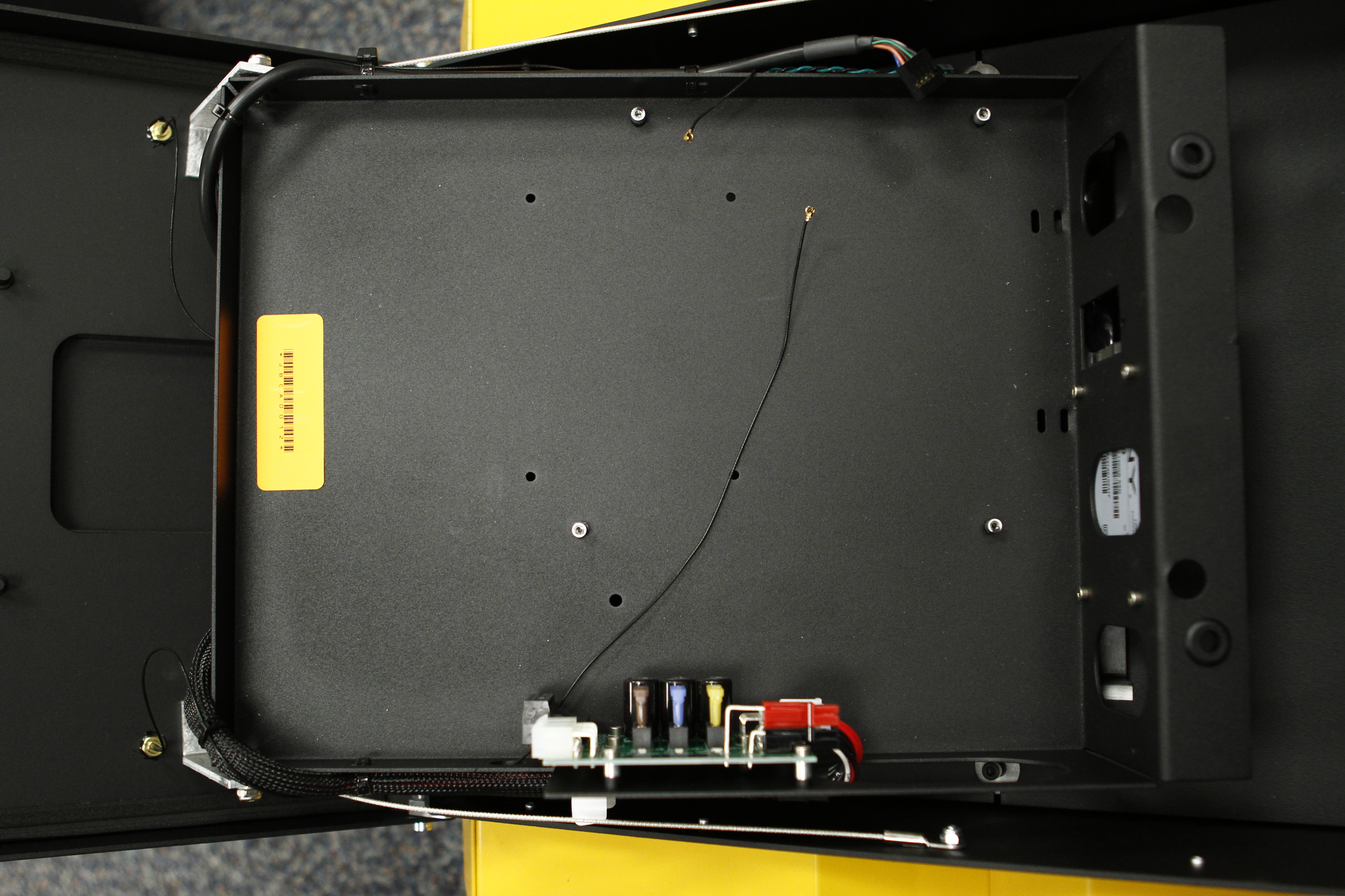
Removing the Mini-ITX Remove the cable ties holding the USB header, power switch signal and antenna wire. The Jetson Nano doesn't have a USB header so it will have to be replaced with a USB mini cable. You will need extra slack in both the antennae cables and power switch signal as well.

Removing the zipties Remove the SSD from the outside of the computer tray.
Step 2: Install the Nano
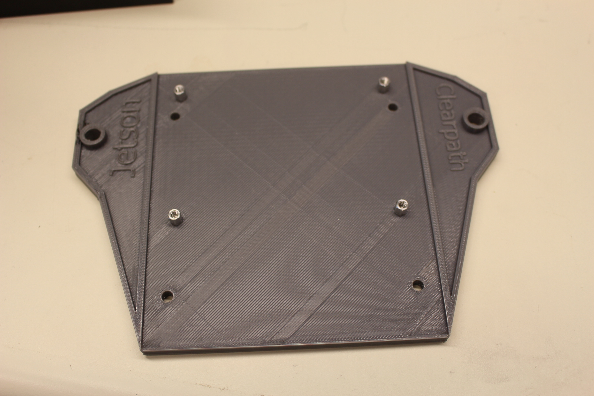
Custom mounting brackets are available on GitHub.
Print off the mount from above using a 3D printer. A 0.2 mm layer thickness should be sufficient.
Add 4X M3 stand-offs to the board mount points. A 6 mm height is recommended.
Installing the standoffs Use M3 screws to fasten the Nano to the mount.
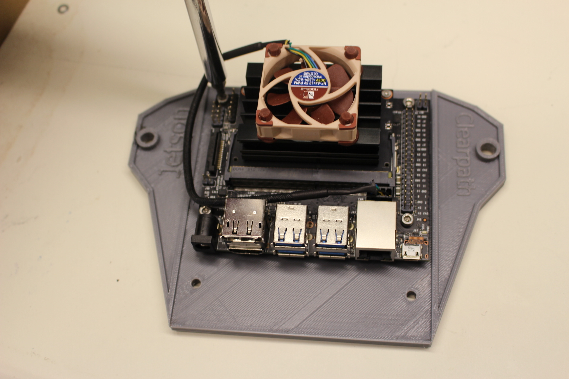
Fastening the Nano to the mount Position the Nano with the mount over the rear two PEMs on the tray and fasten with M3 screws and washers.
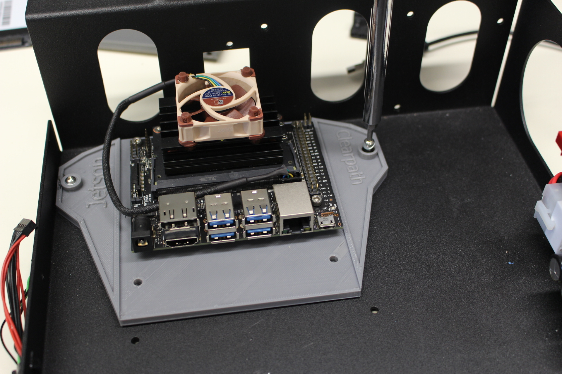
Attaching the mount to Jackal Make a power cable that connects to the 12 V user power (Molex connector) to a barrel connector with center positive. Refer to the Jackal User Manual for the pinout of the user power.
dangerDo NOT plug this into the ITX power plug on the power distribution board.
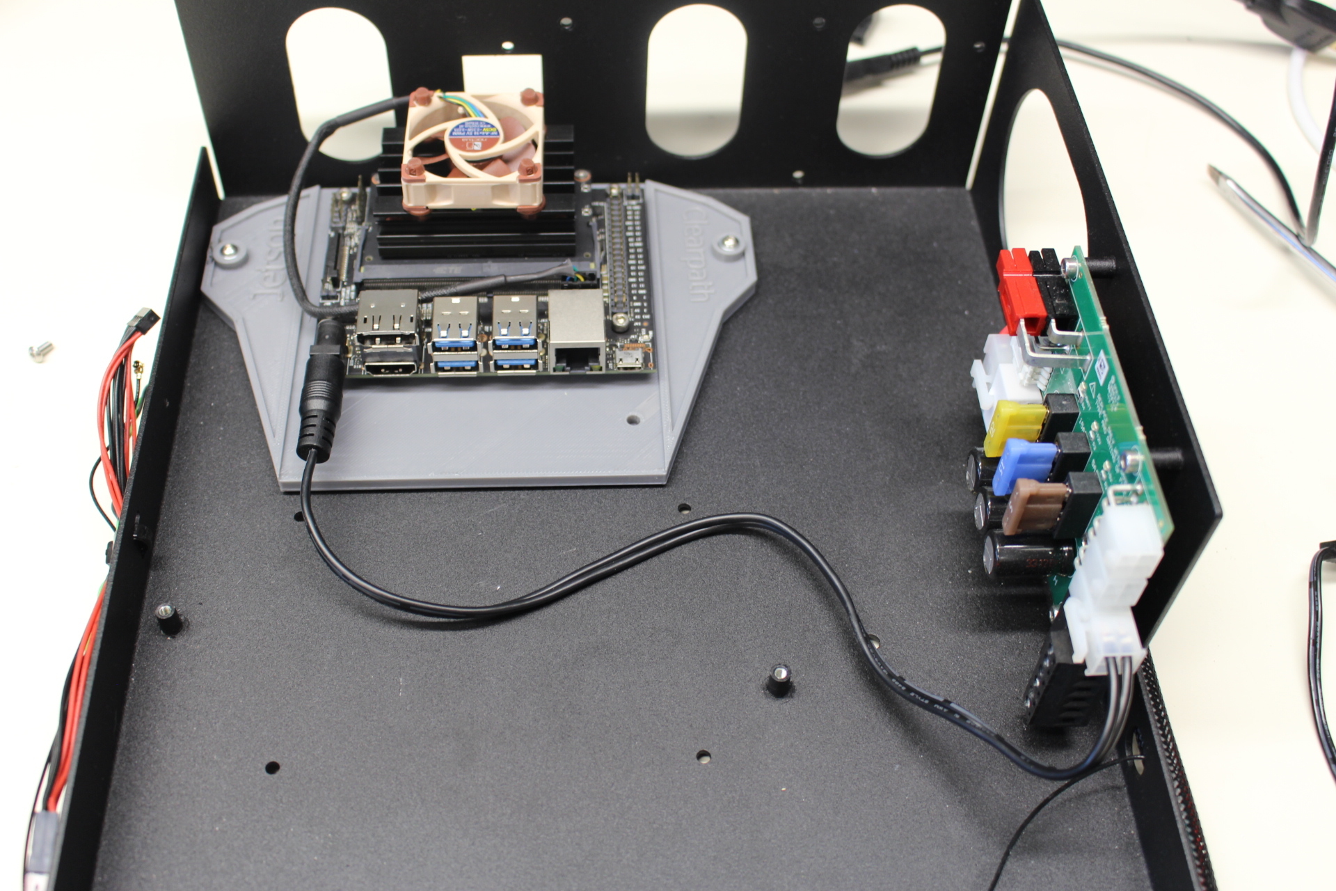
Adding the power connector