Warthog Integration
To attach custom hardware to Warthog, you will have to take care of mechnical mounting, electrical supply, and software integration. This section aims to equip you with respect to these challenges.
Mechanical
When determining mechanical mounting, you have two options, both of which are described below.
- the "Standard" aluminum extrusion interface
- the "PACS™" mounting system and associated kits
Mechanical, Standard
A standard Warthog includes thru holes on the sides of the battery compartment. You can besign mounting brackets to interface with these holes.
Mechanical, PACS™
PACS™ is a Clearpath Robotics standard. We add a grid of M5×0.8 holes onto the top plate of the robot. This grid of holes has a 80 mm X 80 mm spacing. You can create your own brackets to interface with these holes, or can use an existing Clearpath Robotics designed bracket.
Our Sensors and Accessories pages indicate the required bracket for the particular attachment.
Refer to the following pages for Warthog brackets that can simplify your integration.
Common Mechanical Integration Guidelines
- 705 mm (27.75") is the maximum allowed width of any installed payload (this assumes that the payload is also centered across the width of the UGV chassis.
- No part of the payload may extend over the sheet metal housings of the drive units or into the small 50 mm (2") gaps between the chassis and drive units. Damage to both the UGV and the payload will result.
- The chassis has a removable access cover measuring 1175 mm X 667 mm (46.25" X 26.25"). This access cover is supported underneath by two adjustable cross members. Regardless of payload, it is imperative that both cross members remain installed (approximately evenly spaced) to provided required support to the access cover. Consider that any payload installed above the top deck will prevent access to the chassis through the access cover, without first removing the installed payload.
- The rotation of the suspension differential link in the horizontal plane will allow the payload to extend beyond the chassis top deck in both fore and aft locations. The amount of this payload extension (overhang) is dependent on several factors, including the weight and method of attachment of the payload as well as the terrain in which the UGV will operate. Ensure that the amount of overhanging payload allows the UGV to operate safely and does not contact the terrain, especially when crossing steep and/or deep gullies.
- The available internal chassis volume is:
- Length of 445 mm (17.5")
- Width of 660 mm (26")
- Height of 241 mm (9.5"). This space is located at the center of the chassis between two battery packs. Consider that anything placed inside the chassis must be secured as to not move or shift during UGV operation.
Permanent damage resulting from custom modifications to the mounting plate is not covered under warranty and may not be supported by Clearpath Support. Please contact our Support team if you require assistance or have any questions relating to custom modifications.
Electrical Integration
For continued protection against risk of fire, only replace fuses with those of the same type and rating.
Except for bus-powered USB cameras, most payloads have separate leads for power and data.
Top Plate Power and Data Connections Connections
| Description | Notes | Mating Connector (CPR Item) | Mating Connector (Manufacturer Item) |
|---|---|---|---|
| USER POWER | 12 V, 24 V, 48 VBAT; each fused to 10 A | 015016 | RR-153274-23050 |
| USB 3.0 | Male USB type-A | ||
| ETHERNET RJ45 | Male RJ45 | ||
| SERIAL | 015015 | RR-153274-23040 |
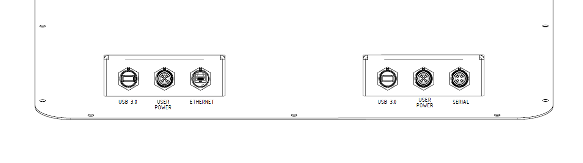
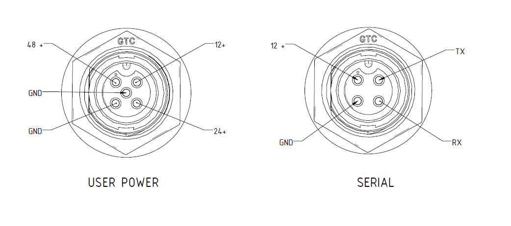
The user power receptacles located in the User Panel are capable of supplying 12 VDC, 24 VDC, and unregulated battery voltage (48 - 60 VDC) for powering Warthog's payloads. See the figures below for connector locations and pinouts. Ensure you select a contact that's appropriate for the gauge of wire used.
The user power breakouts are intended for small sensors, like lidar and cameras. Warthog's 48 V battery pack is fused at 275 A (13200 W). We often add DC-DC and DC-AC supplies inside the Warthog to power large devices like manipulators, lights, and other custom integration attachments.
Refer to the process described on our Power Supplies page to help you choose a power supply or inverter.
Always use adequately sized fuses for your selected wire thickness to prevent electrical fires.
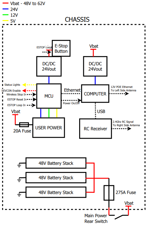
System Electrical Diagram
Software Integration
ROS has a large ecosystem of sensor drivers, some of which include pre-made URDF descriptions and even simulation configurations. Refer to Sensors supported by ROS.
For the best experience, consider purchasing supported accessories from Clearpath Robotics for your robot, which will include simulation, visualization, and driver support.
Refer to the following for more details:
Support
Clearpath is committed to your success. Please get in touch with us and we will do our best to get you rolling again quickly: <support@clearpathrobotics.com>.
To get in touch with a salesperson regarding Clearpath Robotics products, please email <research-sales@clearpathrobotics.com>.
If you have an issue that is specifically about ROS and is something which may be of interest to the broader community, consider asking it on Robotics Stack Exchange. If you do not get a satisfactory response, please ping us and include a link to your question as posted there. If appropriate, we will answer on Robotics Stack Exchange for the benefit of the community.