Husky Observer User Manual
Introduction
Husky Observer is a fully integrated system that enables robotics developers to accelerate inspection solutions. Built on top of the versatile Husky base platform, Husky Observer enables robotics developers to fast-track their system development. With it, you can get your test application running faster without worrying about autonomous navigation and sensor integration.
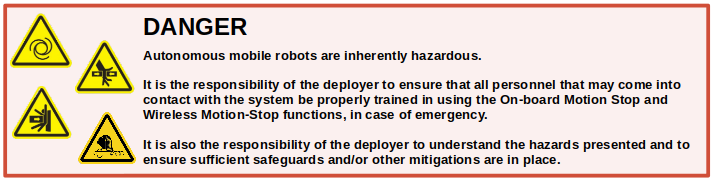
Mobile robots are inherently hazardous. It is the responsibility of the deployer to ensure that all personnel that may come into contact with the system are trained properly. It is also the responsibility of the deployer to understand the hazards presented and to ensure sufficient safeguards or other mitigations are in place. Refer to the Safety section of this manual for further details.
Shipment Contents
Your Husky Observer shipment contains the following:
- Husky Observer robot
- Lockout keys (2X)
- Wireless charging transmitter and dock
- Wired charging adapter
- PS4 controller (for manual operation)
- Tablet (optional)
- Base Station (optional) + power supply
If you purchased standard payload modules or custom integration services with Husky Observer, then additional equipment will be included per your specific configuration, plus further documentation as required.
Hardware Overview
System Architecture
Husky Observer is built around a computer running Ubuntu, paired with a 32-bit microcontroller MCU. The MCU handles power supply monitoring and motor control, with all remaining processing handled by the computer. The communication channel between the MCU and computer is a serial connection.
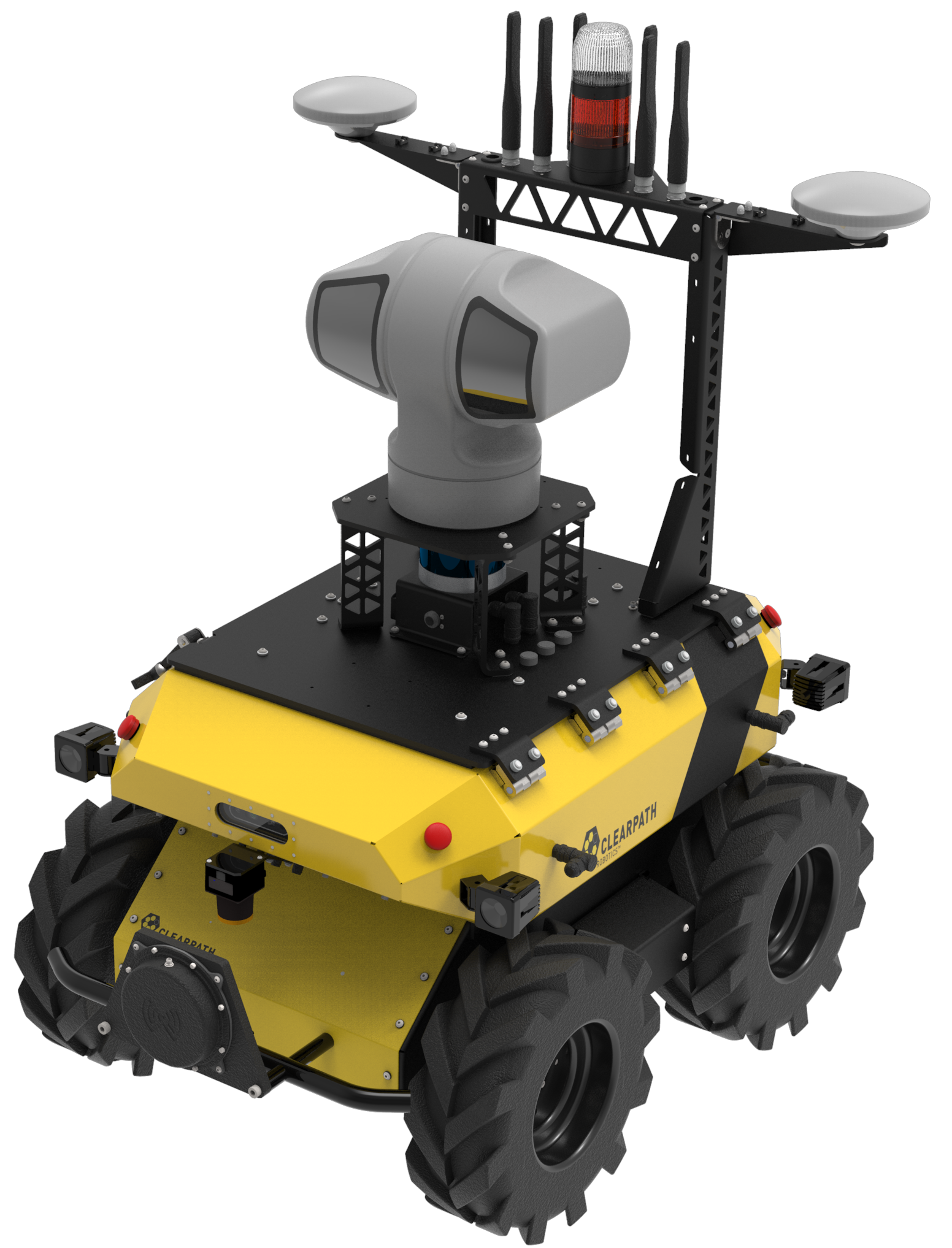
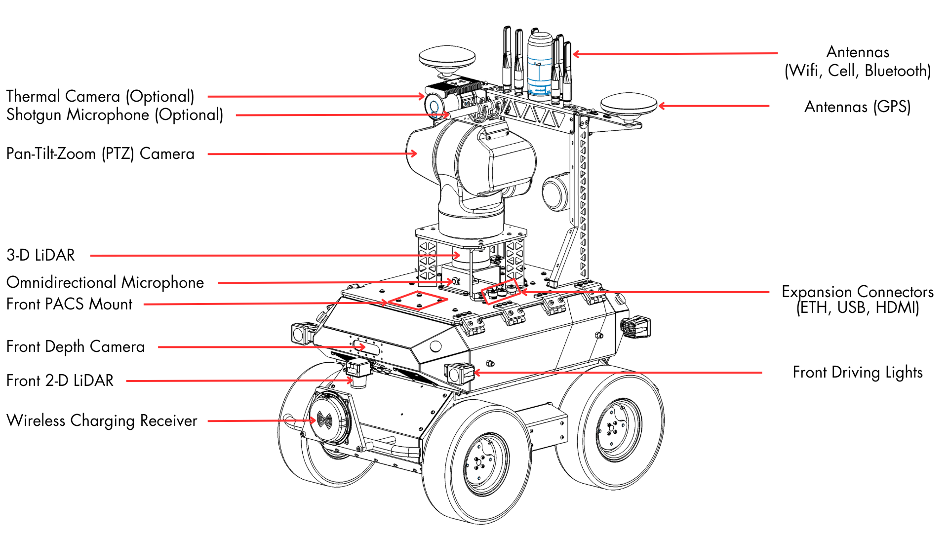
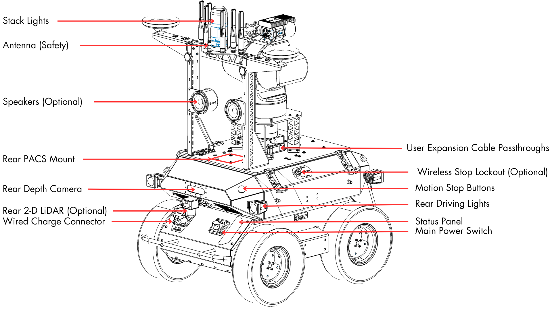
Exterior Features
The Husky Observer exterior is shown below and includes:
- Pan-tilt-zoom (PTZ) camera
- Thermal camera (optional)
- Shotgun microphone (optional)
- Antennas (cellular, wifi, GPS, safety)
- Stack lights
- 3-D LiDAR
- Expansion connectors (power, ethernet, USB)
- Front and rear expansion mount points
- Front (standard) and rear (optional) 2-D LiDARs
- Front and rear depth cameras
- Motion stop buttons
- Wireless motion stop function (optional)
- Omnidirectional microphone
- Front and rear driving lights
- Wireless charging receiver
- Wired charge connector
- Main power switch
- Status panel
Stack Lights
The stack lights are composed of two lights, the details of which are described below.
- The bottom is an orange strobe light that is enabled when the robot is in motion or may soon be in motion; personnel near the robot should exercise caution when this light is strobing.
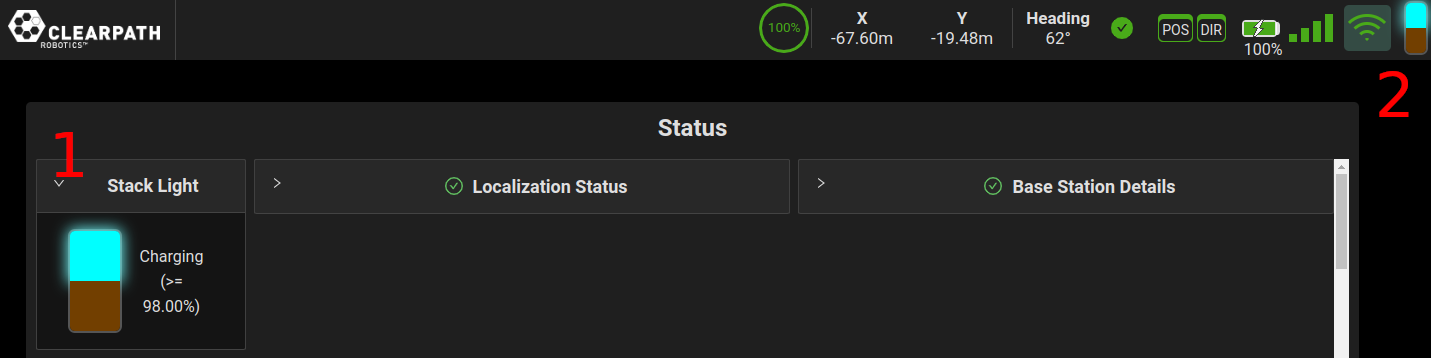
- The top is a multi-colour light that indicates the system status.
| Strobe Light (bottom) | Status Light (top) | Robot State |
|---|---|---|
| Off | Red | Motion stop engaged; robot prevented from moving. |
| Off | Purple | A system error/warning exists; see the OutdoorNav UI for details. |
| Off | Cyan/White | Battery charging in progress and battery over 98% charged (as reported in OutdoorNav UI). |
| Off | Cyan/Green | Battery charging in progress and battery 58% to 98% charged (as reported in OutdoorNav UI). |
| Off | Cyan/Yellow | Battery charging in progress and battery 16% to 58% charged (as reported in OutdoorNav UI). |
| Off | Cyan/Red | Battery charging in progress and battery less than 16% charged (as reported in OutdoorNav UI). |
| On | Yellow | Low battery (battery less than 16% charged). |
| On | Green | Robot is driving (teleop mode). |
| On | Blue | Robot is driving (autonomous mode). |
| On | White | Robot is ready to drive, but currently idle. |
The stack lights can be muted by calling the /lights/set_stack_mute service with a value of True. Users can also override Idle, Teleop and
Autonomous LED patterns by publishing to the /lights/custom_stack_pattern topic at 2Hz or faster. This topic takes a StackLightState message
object as input which consists of the following parameters:
RYG color- The RYG color of the stack light's top lightbool strobe_on- Boolean flag for whether the strobe light is on or notstring message- Human readable message for this particular stack light state
The charging, error and warning states will override any custom patterns.
The stack lights can also be visible in the UI in both the upper right hand corner and as a widget in the status page.
See also additional status as reported in the Status Panel.
Status Panel
The status panel, which complements the Stack Lights, is a display of LED indicators located on the rear of the chassis that provides information about the current status of Husky Observer. The indicators are described in the table below.
| Icon | Description |
|---|---|
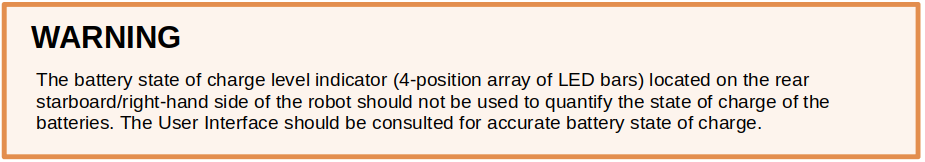
 | Battery Status This is not used on Husky Observer. Refer to the battery state indicator in the OutdoorNav UI or on the stack light instead. |
 | Communication Status When green, Husky Observer is receiving a stream of correctly-formatted motion commands, and is ready to drive. When yellow, Husky Observer is receiving commands, but will not drive due to motion stop or another error. When red, serial communications are currently timed-out. |
 | General Error Status Illuminates red when Husky Observer will not drive due to an error state. Such states include motion stop, insufficient battery power, or an unspecified software error. |
 | Motion Stop Status Illuminates red when Husky Observer will not drive due to the motion stop being activated, either onboard or wireless (if available). |
 | Charge Indicator Illuminates red when Husky user power is being supplied externally. |
Switches and Buttons
Main Power Switch
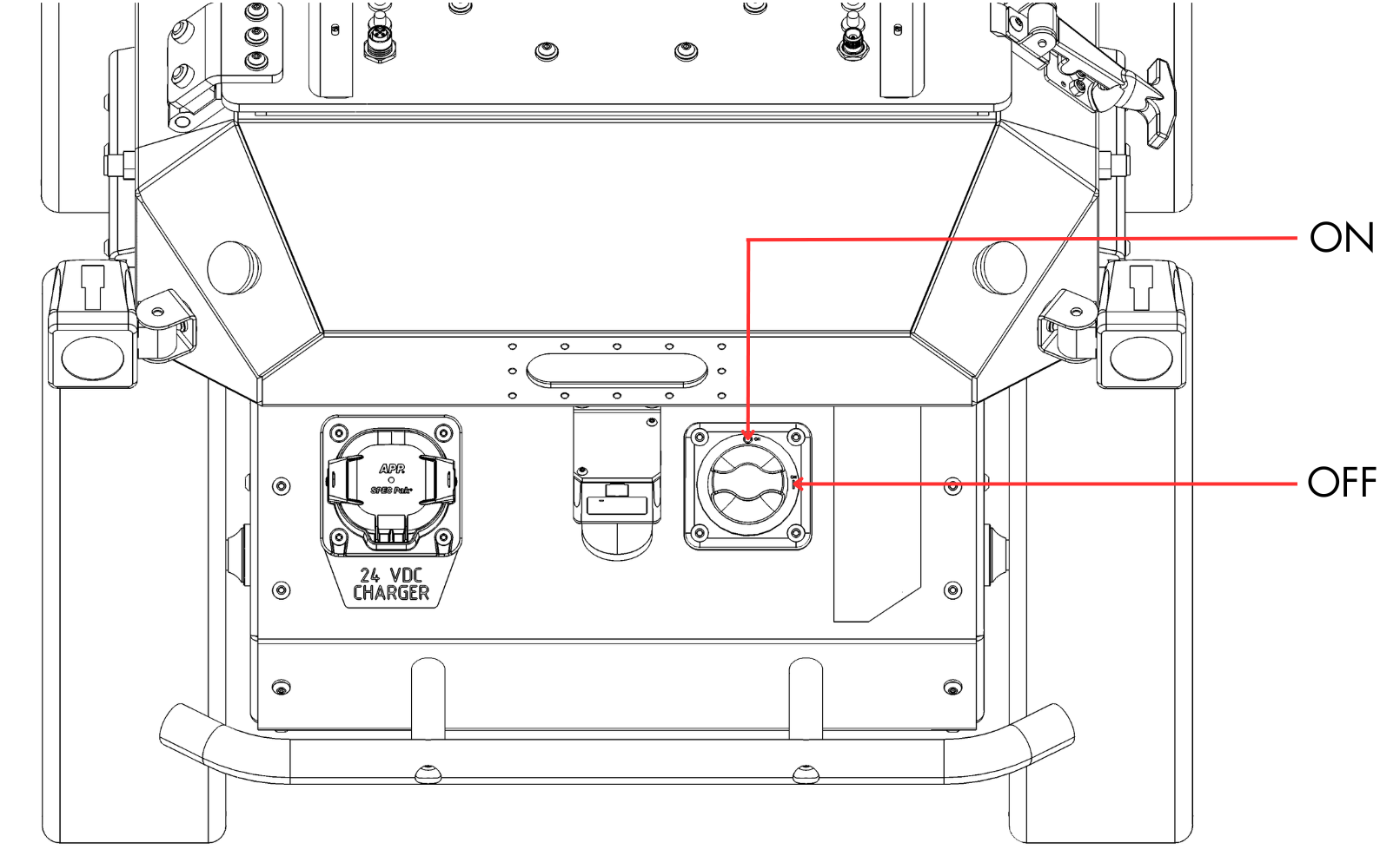
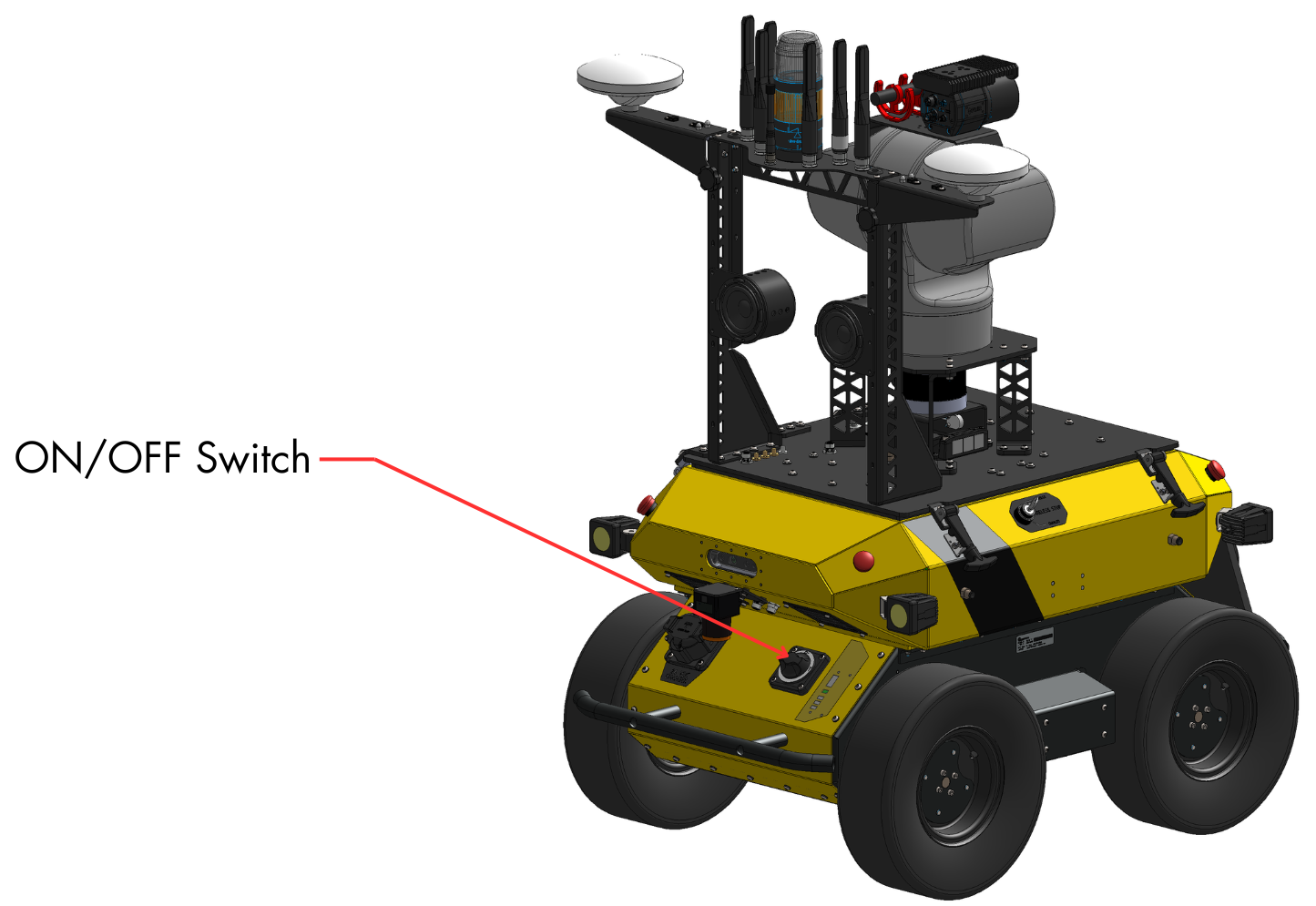
On the rear of the robot, the main power switch can be used to turn the entire system OFF and ON.
Motion-stop Buttons
There are four motion-stop buttons on the robot, one at each of the four corners. Depressing any of these four buttons will engage motion-stop and remove power from the robot motors. Refer to the Safety section for further details.
Motion-stop Override Key Switch
In addition to the motion-stop buttons on the robot, if your Husky Observer is equipped with a wireless motion-stop function, it is possible to disable this function with the override key switch. Refer to the Safety section for further details.
Payloads
Additional payloads can be integrated with Husky Observer, either as part of your purchase or installed after receiving your Husky Observer. Refer to Husky Observer Integration for details on how to integrate your own payload or how to integrate a payload kit from Clearpath Robotics. Each payload kit that ships from Clearpath Robotics comes with a custom mounting bracket and cabling for easy attachment to Husky Observer.
Orientation References
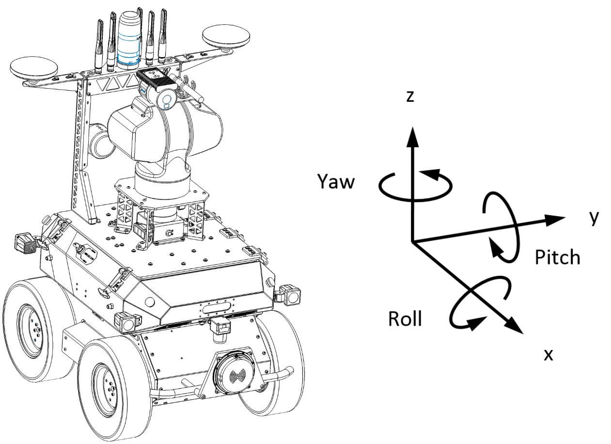
The reference frame used by all Clearpath Robotics ground robots is based on ISO 8855, and is shown in the figure below. Husky Observer's front is shown. When commanded with a positive translational velocity (forward), wheels travel in the positive X-direction. The direction of the axes differs from those used for roll, pitch, and yaw in aircraft, and care should be taken to ensure that data is interpreted correctly.
System Specifications
| Specification | Measurement |
|---|---|
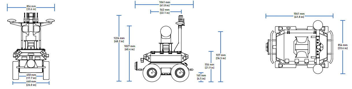
| Dimensions | 1061 mm (length) X 854 mm (width) X 1224 mm (height) |
| Track Width | 550 mm |
| Wheelbase Length | 512 mm |
| Ground Clearance | 130 mm |
| Mass | 98.5 kg |
| Maximum Payload | 10.0 kg |
| Speed, Maximum | 1.0 m/s |
| Climb Grade | 15 ° |
| Traversal Grade / Sideslope | 15 ° |
| Ambient Operating Temperature | -10 to + 40 °C |
| Environmental | Designed for IP55 |
| Operating Time, Typical | 2.5 to 3.25 hours |
| Operating Time, Standby | 4.0 hours |
| Battery | 35 Ah @ 24 V, LiFePO4 |
| Wireless charging | Up to 300 W (approximately 4 hours to charge from 10 to 85% when powered on in low power mode) |
| Wired charging | 650 W (approximately 1 hour to charge from 10 to 85% when powered off) |
| Expansion | 2.5 A @ 24 V, 3.5 A @ 12 V, 3.75 A @ VBAT, USB 3.0, Ethernet (data only, 1 Gbps), HDMI |
Safety
General Safety Notices
Important Safety Information
General Hazard Labels
Review the following to learn more about the labels that may be used on Clearpath Robotics products. Hazards can also apply to attachments and accessories used in conjunction with a Clearpath Robotics product.
| Label | Label Title | Label Description |
|---|---|---|
 | Automatic Motion Hazard | Clearpath Robotics robots may suddenly begin moving autonomously or when being driven manually. Always be aware of Clearpath Robotics products and their potential for movement. |
 | Crushing Risk | Objects or personnel can be crushed between the Clearpath Robotics robot and another object. Keep hands and other objects clear of crush points at all times. Keep clear of all docking Clearpath Robotics robots. |
 | Electrical Shock Risk | Clearpath Robotics robots contain circuitry and batteries that may cause electrical shock if not properly insulated. |
 | Entanglement Risk | Clearpath Robotics robots as well as their sensors can lead to entanglement for hair or dangling materials during their rotation. Keep dangling materials/hair away from Clearpath Robotics robots during motion. |
 | Environmental Hazard | Clearpath Robotics robots contain batteries and materials that may require special disposal methods. Consult local regulations. |
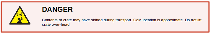
 | Falling Object Risk | Beware of objects that may have shifted in any Clearpath Robotics robot crate as they pose a risk of falling when opened. |
 | High Surface Temperature Risk | Robot PC heat sinks and robot motors can become extremely hot during operation. |
 | Impact Risk | Clearpath Robotics robots travelling through a facility can potentially impact objects and personnel. Keep clear of all docking Clearpath Robotics robots. |
 | Laser Radiation Risk | Clearpath Robotics robots may use Class 1 laser products. These provide no hazard during normal use, however it is not recommended to stare directly into the beam(s). |
 | Material Hazard - Lithium | Robot batteries contain harmful material. Always use proper handling procedures when handling robot batteries. |
 | Manual Load Lifting Risk | Always use ergonomic techniques when manually lifting loads. |
 | Pinching Risk | Keep hands and other objects clear of pinch points at all times. Keep clear of all docking Clearpath Robotics robots. |
 | Radio Frequency Risk | Clearpath Robotics robots and/or accesories may use radio frequency (RF) radiating antennas. These provide no hazard during normal use, however prolonged exposure around the antenna is not recommended. |
 | Tripping Hazard | Clearpath Robotics products may pose a tripping hazard. |
Safety Awareness
Personnel present during the operation of a Clearpath Robotics robot need to be made aware or be accompanied by personnel who are familiar with the specific risks and hazards associated with automated mobile robots (AMR). The following checklist identifies basic topics that should be addressed by site-specific worker and visitor safety orientation training.

- Proper PPE must be worn, including safety footwear (ie. steel toe).
- Crossing into the path of a moving Clearpath Robotics robot should be avoided, as well as placing or throwing obstacles into the path of a moving Clearpath Robotics robot.
- Be aware that a Clearpath Robotics robot can be anywhere in the operating area of the facility at any time, and may pose a tripping hazard even when not in motion.
- Personnel need to be aware of the Clearpath Robotics robot docking and charging areas, where detection fields are reduced.
- Personnel should be aware that Clearpath Robotics robot LiDAR safety scanners use a class 1 laser and high intensity LEDs.
- Personnel should keep all loose clothing and body parts away from Clearpath Robotics robots, accessories, attachments, and payloads, while they are in autonomous operation. Using a Motion Stop button is the only acceptable manner of interacting with a Clearpath Robotics robot or attachment while it is being operated autonomously.
In addition to the preceding basic items for all workers and visitors, the following should be considered for facility personnel, including drivers of other robots:
- When required to move a product manually, personnel must ensure it is in an Motion Stop state or shut down completely and should not push manually for prolonged periods.
- Alert personnel that while operating a Clearpath Robotics robot outside of the Autonomy State, they are solely responsible for obstacle and collision avoidance.
- Maintenance not outlined in either this document or the operations and maintenance manual can only be performed by a Clearpath Robotics Authorized Personnel.
Operating Environment and Intended Use
The autonomous mobile robot system is intended for use in:
- indoor and outdoor industrial and commercial environments;
- environments free of vertical drops greater than 200 mm;
- environments free of fast-moving people or vehicles;
- environments free of glass or transparent plastic floors or walls;
- temperatures between -10 °C and +40 °C;
- environments free of open water or other liquids deeper than 20 mm;
- environments free of grades greater than 12%.
The system is intended to be operated by trained personnel familiar with autonomous mobile robotic technology. It is intended to be monitored constantly by those personnel during operation.
The system is intended to be operated around trained personnel familiar with the hazards that the system presents.
The system is intended to be operated in the as-furnished condition, without additional equipment, payload or passengers.
Disclaimer
It is the responsibility of the user to be familiar with all applicable safety standards and ensure that the hardware, software, and/or services delivered by Clearpath Robotics (collectively referred to as the "Product") are maintained and operated in a safe manner, in a suitable environment, and in accordance with the recommended maintenance requirements prescribed by Clearpath Robotics.
Without limiting the foregoing, it is the user's responsibility to ensure that personnel operating the Product are adequately trained and comply with all laws, regulations, codes, and safe practices, including health and safety and workers' compensation laws, applicable to the user's activities and its ownership, possession, and use of the Product. Modification, removal or addition of components, or changes to the functionality or operation of the Product in any way, except as expressly authorized by Clearpath Robotics, may jeopardize the safety of the Product.
The robot system and its associated equipment, including all safety functions, are provided "as-is". Clearpath Robotics makes no claim that the achieved residual risk to persons, property or animals is tolerable, or meets any generally-accepted threshold. Residual risk is user- and use-specific. Evaluation of tolerable residual risk is subjective.
Clearpath makes no claim that the degree of safety function reliability is commensurate with the degree of risk reduction those safety functions ostensibly provide. The system operator is responsible for the safe use of the robot system and associated equipment. Clearpath disclaims all responsibility for injury to persons or animals, or damage to property resulting from the use of the robot system and its associated equipment.
Additional review by local Authorities-Having-Jurisdiction, Nationally-Recognised Testing Laboratories, Notified Bodies, or others may be required to establish that the system as-used achieves tolerable residual risk. The operator is responsible for additions or modifications to the system that may be mandated or recommended by third-parties. Clearpath may provide system documentation to support a third-party review, but shall not be held responsible for meeting third-party expectations for content, completeness, style or conformance to any standard.
If at any time you have any questions or concerns regarding the safe operation of your Clearpath Robotics product, contact Support.
Recommended Safe Work Procedures
Clearpath Robotics recommends the following procedures be followed to reduce the likelihood of harm.
- Maintain a safe distance of at least 10 m from the robot whenever possible.
- Never assume that the robot can be reliably stopped on command.
- Assert a stop using the remote stop device (if present) before approaching the robot.
- Never place the remote stop device (if present) on or inside the robot.
- Always be vigilant around the robot, even when a stop is asserted.
- Perform no maintenance or troubleshooting on the robot without training and familiarisation.
- Follow electrical safety best practices when working with electrical systems and components.
- Disconnect battery using main disconnect of the robot before working inside robot.
- Wear personal protective equipment including high-visibility clothing, head and eye protection while operating, observing or working on the robot.
- Never climb on or ride the robot.
- Never lie on the ground under or near the robot.
- Avoid operating the robot on slopes and grades.
- Never stand downhill of the robot.
- Operate the robot at the lowest speed possible.
- Never attempt to defeat a safety function for any reason.
- Chock the robot's wheels when the robot will be stationary for more than a few seconds.
- Never work on the robot while it is on a slope.
- Replace fuses only with identical product from specified manufacturer.
- Discontinue use and contact Clearpath Robotics support at the first sign of strange robot behaviour.
- Keep tools and loose parts away from electrical components and out of the robot's bays.
- Check the functionality of stop systems on a regular basis, including before and after each use.
Husky Observer Safety Notices
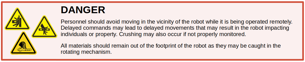
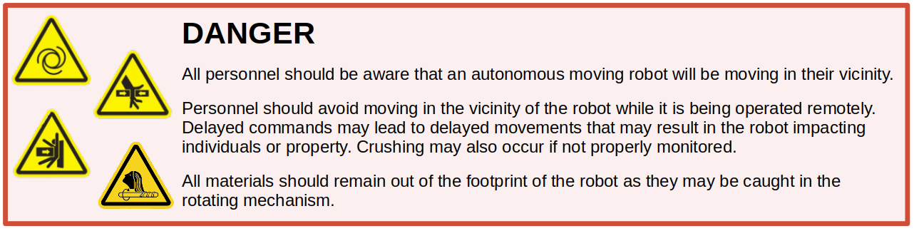
Unexpected Motion
Autonomous and teleoperated robots may begin moving, stop, or change direction unexpectedly. They may move in an unintuitive way. Always maintain physical separation from the robot when it is in motion or capable of starting motion.
Sensor and Response Limitations
The sensors that the mobile robot uses to navigate within its environment and avoid obstacles have limited performance. Examples of common limitations include range, fidelity, response speed, and refresh rate. Some sensors, such as the LiDARs used for collision avoidance, may be unable to detect some materials, such as glass. Always treat the robot as a collision hazard. Proper maintenance/cleaning should be undertaken on the sensors to ensure their optimal performance.
Stability, Traction, and Stopping Distance Limitations
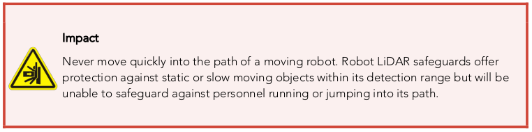
The robot's ability to take action in response to sensor input is also limited. The amount of traction the robot can generate on different surfaces is limited, and may not be sufficient to maintain its position. For example, a robot on an icy grade may slide uncontrollably. The reaction time and stopping rate of the robot is limited. The robot may not have enough time to stop if an obstacle appears suddenly in the robot's path. Never run or jump into a moving robot's path. Never operate the robot in environments other than those for which it is intended.
Electrical Subsystem
Husky Observer is powered by two 12 V Lithium-Iron-Phosphate (LiFePO4) batteries in series to make a 24 V pack. These batteries are similar to the type found in electric wheelchairs, golf carts, fork trucks, and other devices. Husky Observer's battery pack is capable of delivering 5565 W, three times the power of a standard wall outlet. This gives Husky Observer's motors their great performance, however, it is also enough power to cause severe bodily harm.
Note that the Husky Observer PDU has a 50 A fuse that limits the continuous power output to 1325 W.
Please observe the following precautions:
- Turn the Main Power Switch to "OFF" when working on Husky Observer's hardware.
- The Main Power Switch isolates the energy from the switch to the rest of the robot. This potential energy is still present at the battery terminals, and the cable connecting the switch to the batteries.
- Do not tamper with the battery packs.
- Charge the battery only with the charger provided by Clearpath Robotics.
- Please dispose of the batteries properly according to local regulations.
Lifting and Transport
For the safety of users and to maximize the lifetime of Husky Observer, please observe the following when manually transporting the robot:
- Husky Observer should be lifted by two persons, firmly gripping the front and rear bumper-bars.
- Ensure that Husky Observer is in Motion-Stop mode when transporting short distances and powered off when transporting longer distances.
- It is not advised to push Husky Observer, as this can cause damage to the motors.
Performance Considerations
Included in Husky Observer are native software checks and limits to protect the robot.
However, it is recommended to monitor the system's status during usage with the /status and /diagnostics topics
or through the OutdoorNav UI as described in Monitoring System Status.
These topics provide useful information regarding voltages, currents, temperatures and general health of the system.
The total current draw does not include the motors drivers; it is the current consumed by the MCU and user power ports. Husky Observer's motors are rated to draw 10.7 A continuous, but they will spike to several times higher than this, particularly when traversing rough terrain and when turning on the spot. To reduce current draw, consider commanding wider-radius turns from your control software.
The temperature is measured in the motor drivers and on the motor casings; the coils inside the motor casings cannot be measured. Therefore, it is important to note that the temperature measured on the motor casings is a lagging indicator of the temperature of the coils inside the casing. Be aware of the delay in heat propagation on the motors during heavy use. The thermal limit of the system is 50 °C, and components of the system will begin to throttle or shut down if internal temperatures exceed this limit. Monitoring these fields over longer periods of operation will allow you to ensure that you are not putting excessive wear on Husky Observer's motors.
Husky Observer Safety Features
Onboard Motion-Stop Function
The mobile robot includes an onboard motion-stop function that allows a person in the physical vicinity of the robot to halt its motion and prevent re-initiation of motion. This function can be asserted by pressing any one or more of the four red stop actuators present around the periphery of the mobile robot as shown in the figure below.
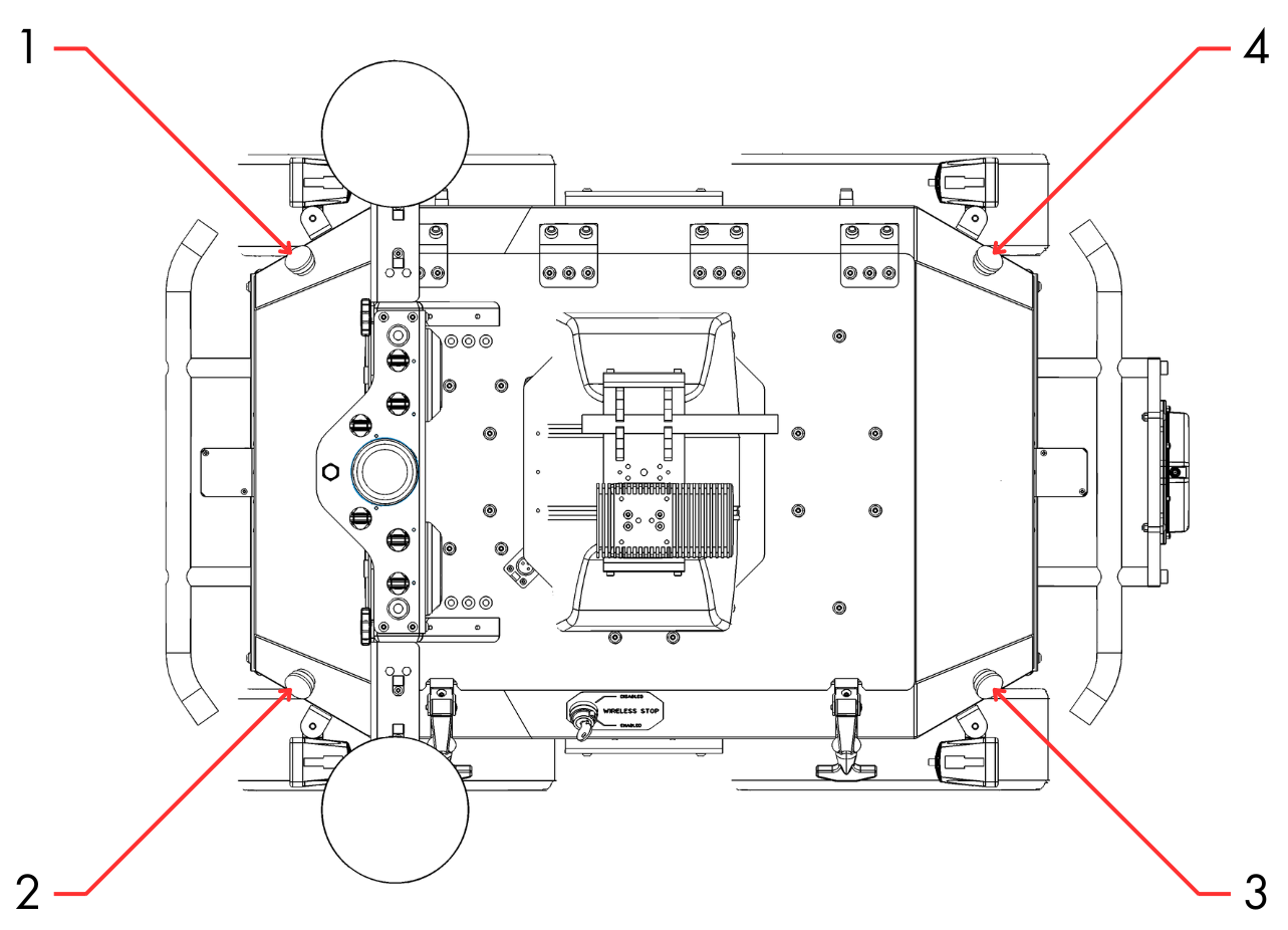
The motion-stop function can be reset by twisting all depressed actuators until they return to an extended position. There is no second "start" action required to reset the stop function. The robot may begin moving again immediately after the final stop actuator has returned to its extended position.
The onboard motion-stop system is intended for use in emergency situations. The motion-stop system should not be used as the means of controlling robot motion during regular operation.
Wireless Motion-Stop Function (Optional)
In addition to the onboard motion-stop function, the system may include an optional wireless motion-stop function. This function allows a person who is physically separated from the robot to halt its motion and prevent re-initiation of motion.
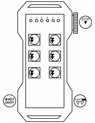
To assert the stop function:
- depress the red push-button actuator on the side of the provided controller.
To reset the stop function:
- twist the depressed actuator until it returns to its extended position;
- depress and hold for 1 second the black start button on the side of the controller.
The wireless motion-stop function is automatically asserted if the robot is not able to communicate wirelessly with the controller. This is to ensure that the stop function does not become unexpectedly non-operational as a result of robot or operator motion, interference, atmospheric conditions, depleted battery, etc. The controller must be powered and within range of the mobile robot to communicate.
The wireless motion stop system is intended for use in emergency situations. The motion stop system should not be used as the means of controlling robot motion during regular operation.
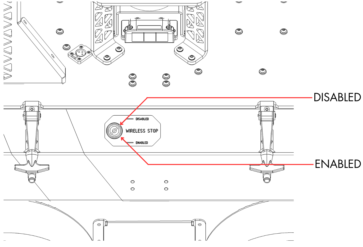
The wireless motion-stop function (but not the on-board motion-stop function) may be overridden by means of a key switch as shown in the figure above. This is to allow the robot to be operated at higher risk while, for example, the controller battery is dead, out of range or not accessible.
Operation of the mobile robot while the wireless motion-stop function is overridden is not recommended. The system deployer/operator assumes all responsibility for injury to persons or animals, or damage to property, arising from the inability to remotely stop the motion of the vehicle due to the use of this override.
Motion Buzzer
When Husky Observer is in motion in any direction, both in manual and autonomous modes, a buzzer will sound to provide an audible warning to personnel in the nearby area. No configuration or operator action is required to enable this feature.
OutdoorNav Autonomous Obstacle Avoidance Function
During and only during OutdoorNav missions (not during OutdoorNav Manual Mode), the 3-dimensional LiDAR is used to perform obstacle avoidance to reduce the risk of the robot colliding with stationary or dynamic obstacles in its environment. The navigation uses the robot's 3D LiDAR scanner to detect obstacles within a certain range. A gradual speed reduction is asserted as the distance to the obstacle decreases and the robot will attempt to move around any obstacle it detects. This may happen several times if the robot has navigated itself into a tight space surrounded by walls. No intervention from the user is required.
The 3D LiDAR scanner used for obstacle detection has a 360° field-of-view in the horizontal plane, and a ±15° field-of-view in all vertical planes with respect to the center of the lens as shown in the figure below. However, some regions of the scanned envelope may be occluded by the robot itself. The LiDAR is unable to detect objects in these regions (and all regions outside the scanned envelope). The obstacle avoidance feature will not respond if obstacles are within those regions.
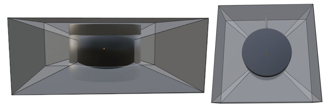
There are also gaps in LiDAR coverage due to the divergence of the laser beams in the vertical direction, and discrete sampling in the horizontal direction. The divergence angle is 2° vertically between beams and 0.1 - 0.4° horizontally between samples (depending on configuration). As a result the LiDAR may fail to detect the approach of slender or pointed objects.
The LiDAR data is filtered to reduce false-positives. It is possible that this filtering could reduce the detectability of certain objects.
Getting Started
Hardware Setup
This section describes how to unpack the system and complete the hardware setup.
Base Station Setup
The Base Station is an optional component. Skip this step if your system does not include a Base Station.
Base Station Location
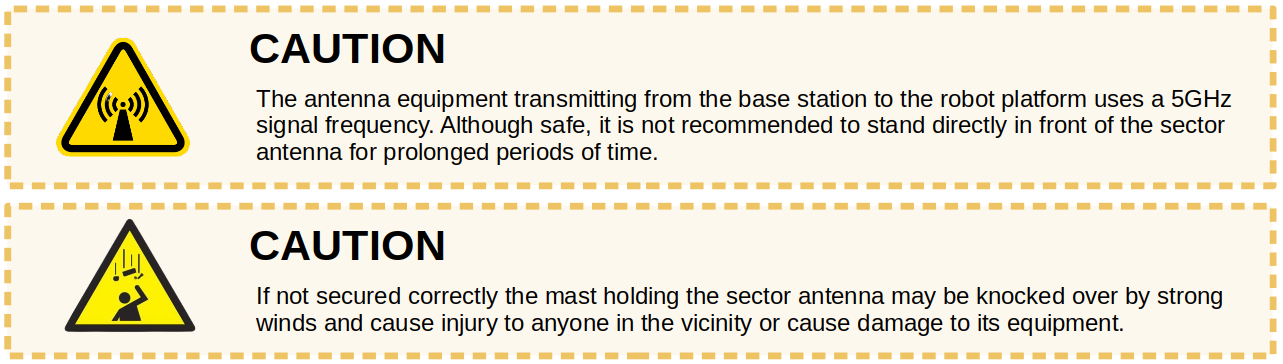
The location of the Base Station, particularly its antenna, will play a critical role in the performance of the outdoor navigation software, especially at long range.
Below is a set of criteria in order of priority, for the location of the Base Station, such that the performance of the networking/software is not degraded:
-
The Base Station should be secured as high as possible so that the GPS antenna can accurately obtain a GPS signal and so that the network antenna can propagate its radio waves without interference from nearby obstructions. For example, a good location could be on the roof of a building or trailer.
-
A location on the ground (if no elevated location is available/accessible) where the Base Station can be secured using the tripod that has been shipped with the robot. If this location is selected, ensure that the tripod is secured a minimum of 10 meters from any buildings or obstructions so that the GPS antenna has a clear view of the sky. Recommended minimum height is 1.75 meters from the bottom of the antenna to the ground.
-
A location where an Ethernet cable can be fed to to connect the Base Station to the WAN (if WAN available).
Base Station Orientation
The robot and Base Station are both shipped with an omnidirectional antennas. As such, there is no need to orient the Base Station to face the robot's area of operation.
Base Station Power
The Base Station is powered by an internal battery. The Base Station also includes a power supply that, when connected, will charge the battery. When connected, the power supply can provide sufficient power both to charge the battery and to operate the Base Station.
To power on the Base Station, press the recessed silver power button on the side of the enclosure. When powered, the button will illuminate blue.
Internet over Base Station Network
If a wired internet connection is available at the user facility, an Ethernet cable can be run from an access point to the Ethernet port on the side of the Base Station case. This will provide internet access for the robot and the tablet. Note that there are two network ports on the side of the Base Station; use the bottommost port for connecting the cable that provides internet access. The other network port provides a local network connection for debugging purposes only.
Note that the connector on the Base Station is an M12 connector (Digikey P/N 1754-1180-ND) and an Ethernet cable with a mating connector must be used for providing internet access.
Autocharge Dock Setup
The Autonomous Docking software enables the robot to navigate toward the dock target and autonomously approach the target to begin charging the robot's batteries. The complete dock consisting of the target, the WiBotic charging unit (transmitter) and the enclosing material can be seen in the figure below.
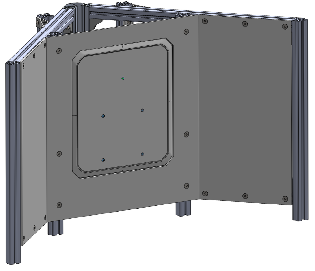
The robot requires open, flat, level ground in front of the dock to manoeuvre. It must have GPS signal visibility (ie. not too close to any tall buildings or trees) and clear line-of-sight to the dock target from all points in this pre-dock region. Allow at least 8 meters from the "pointed" end of the dock and a width of at least 4 meters, as shown in the figure below.
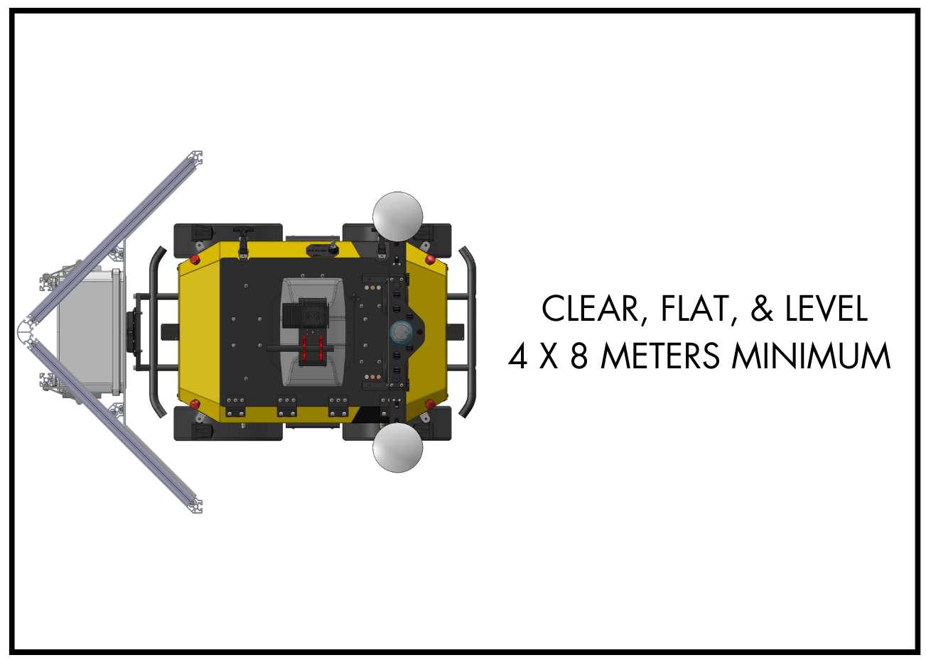
The charge dock, including WiBotic wireless transmitter, ships pre-assembled. Remove it from the crate and position it at the desired location. The concave portion of the target points toward the robot when docked.
The dock may be secured to the ground if desired. If the attachment points are near the transmitter box, non-metallic fasteners and anchors should be used to avoid magnetic interference with the charge system.
Wireless Transmitter
The WiBotic wireless transmitter ships pre-installed in the dock. To complete the installation of the wireless transmitter:
- Plug the wireless transmitter into a power terminal using the provided power cord (an extension cord may be required). The transmitter requires 90 - 264 V AC, 50 - 60 Hz.
- Power ON the wireless transmitter by pressing the switch on the side of the transmitter. The GREEN LED will light up when powered ON, flashing once every three seconds to indicate idle mode.
Wireless Receiver
The WiBotic wireless receiver ships pre-installed on the Husky Observer robot and does not require any customer assembly.
Robot Setup
Unpacking the System
The total mass of the crated system is approximately 300 kg.
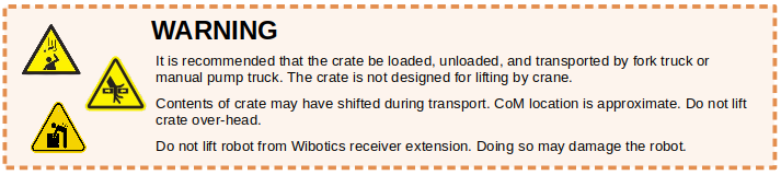
It is recommended that the crate be loaded, unloaded, and transported by fork truck or manual pump truck. The crate is not designed for lifting by crane.
The crate is assembled using 9/16" hex head screws. Both the front and rear panels are held in place with 12 screws. They can be removed with a wrench or impact driver with an appropriate 9/16" socket.
The robot is held in place using ratcheting tie-down straps. Loosen the straps on either side of the robot, and remove them from the crate. In the accessories crate, there is a shelf which may be removed and used as a ramp. Place it behind the robot, bridging the drop between the crate floor and the ground. The robot may then be rolled out by pulling on the rear bumper. Make sure that the ramp does not shift during this process.
Installation of SIM Card (Optional)
An LTE SIM card can optionally be installed into the robot to provide network access when out of range of WiFi networks. A SIM card is not required if Husky Observer is always being operated within range of WiFi networks. Note that the SIM card (and corresponding data plan) is provided by the end user, not by Clearpath Robotics.
- Open the lid on Husky Observer.
- Locate the "Microhard" component, near the rear-left corner.
- Insert the SIM card into the Microhard port labelled "SIM 1".
- Refer to Enabling LTE (Cellular) Networking on Robot for details on the software setup.
Robot Startup
When powering up the robot for the first time, follow these steps:
-
Turn the Main Power Switch to the "ON" position. Note that this switch is set to "OFF" prior to shipping to prevent battery drain during shipping.
-
Wait 10-15 seconds for the startup checks to complete, at which point LEDs on the Status Panel should illuminate and the system will begin booting.
-
Wait one to two minutes for the system to boot fully before proceeding. The external light indicators on the rear of the robot will illuminate once the system is powered. The "COMM" light will notify the user about the status of the computer. The possibilities are:
- GREEN: Communication with the computer is active/stable and robot is ready to drive.
- YELLOW: Communication with the computer is active/stable but Motion-Stop is engaged. Release the Motion-Stop.
- RED: No communication with the robot computer or ROS error.
Charge State
Use the OutdoorNav UI to determine the charge state of the robot batteries.
Motion-stop State
The state of the robot motion-stop function can be determined in two ways: via the Stack Lights and via the Status Panel.
The status stack light illuminates solid red when the motion-stop is engaged and is off or a different color when motion-stop is not engaged.
The second way to determine the motion-stop state of the robot is to inspect the status panel on the rear side of the base Husky. This panel includes "COMM" and "STOP" indicators. When a motion-stop is asserted, the "COMM" indicator will illuminate YELLOW and the "STOP" indicator will illuminate RED. When the robot is powered off the indicators will be off. When the robot is powered on and a motion stop is not asserted, the "COMM" indicator will be illuminated GREEN and the "STOP" indicator will be off.
Charging the Robot
See Maintenance for details on charging the robot.
Robot Expansion and Debug Ports
As outlined in Exterior Features, the robot comes equipped with additional ports (power, USB, Ethernet) that can be used for both system expansion (eg. extra sensors) or for system debugging. All data connectivity is to the main computer. See Husky Observer Integration for further details.
Base Husky Software Setup
Wired Network Connection
During setup or debugging, it may be desirable to connect to Husky Observer through a wired Ethernet connection. After connecting an Ethernet cable from your laptop to the debug/expansion port as shown in the Exterior Features, follow the steps below to establish a network connection to the main computer. It is also possible to access other components on the system using the appropriate IP address (refer to the Networking Configuration for a full list).
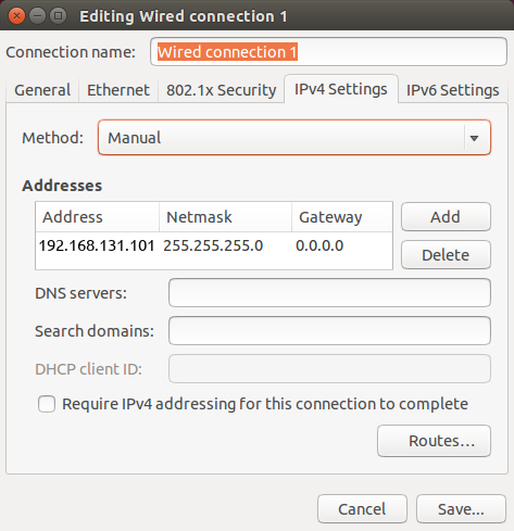
Set your laptop's ethernet port to a static IP such as 192.168.131.101. To do this in Ubuntu, follow the steps below:
- Click on the Wi-Fi icon in the upper-right corner of your screen, and select Edit Connections.
- In the Network Connections window, under Ethernet, select your wired connection and then click Edit.
- Select the IPv4 Settings tab and then change the Method to Manual.
- Click the Add button to add a new address.
- Enter a
192.168.131.101as the static IP under the Address column, and enter255.255.255.0under the Netmask column, and then select Save.
The next step is to connect to your robot via SSH. To do so execute the following in a terminal window:
ssh administrator@192.168.131.1
You will be promoted to enter a password. The default password is clearpath and you set a new password
on first connection.
Changing the Default Password
All Clearpath robots ship from the factory with their login password set to clearpath. Upon receipt of your
robot we recommend changing the password.
To change the password to log into your robot, run the following command:
passwd
This will prompt you to enter the current password, followed by the new password twice. While typing the
passwords in the passwd prompt there will be no visual feedback (e.g. "*" characters).
To further restrict access to your robot you can reconfigure the robot's SSH service to disallow logging in with a password and require SSH certificates to log in. This tutorial covers how to configure SSH to disable password-based login.
Installing Remote Computer Software
This step is optional.
This step assumes that your laptop (ie. "remote computer") is already present on the same subnet as the robot. See System Networking Setup and Appendix A for networking details.
It is often convenient to use a Remote Computer (eg. laptop) to command and observe your robot. To do this, your Remote Computer must be configured correctly.
-
Perform a basic ROS installation. See here for details.
-
Install the desktop packages:
- Husky
- Jackal
- Dingo
- Ridgeback
- Warthog
- Boxer
sudo apt-get install ros-noetic-husky-desktopsudo apt-get install ros-noetic-jackal-desktopsudo apt-get install ros-noetic-dingo-desktopsudo apt-get install ros-noetic-ridgeback-desktopsudo apt-get install ros-noetic-warthog-desktopsudo apt-get install ros-noetic-boxer-desktop -
Configure Remote ROS Connectivity.
Click to expand
To use ROS desktop tools, you will need the Remote Computer to be able to connect to your robot's ROS master. This will allow you to run ROS commands like
rostopic list,rostopic echo,rosnode list, and others, from the Remote Computer and the output will reflect the activity on your robot's ROS master, rather than on the Remote Computer. This can be a tricky process, but we have tried to make it as simple as possible.In order for the ROS tools on the Remote Computer to talk to your robot, they need to know two things:
- How to find the ROS master, which is set in the
ROS_MASTER_URIenvironment variable, and - How processes on the ROS master can find the Remote Computer, which is the
ROS_IPenvironment variable.
The suggested pattern is to create a file in your home directory called
remote-robot.shwith the following contents:export ROS_MASTER_URI=http://cpr-robot-0001:11311 # Your robot's hostname
export ROS_IP=10.25.0.102 # Your Remote Computer's wireless IP addressIf your network does not already resolve your robot's hostname to its wireless IP address, you may need to add a corresponding line to the Remote Computer's
/etc/hostsfile:10.25.0.101 cpr-robot-0001noteYou can verify the hostname and IP address of your robot using the following commands during an SSH session with the Onboard Computer.
hostname
hostname -i
Then, when you are ready to communicate remotely with your robot, you can source that script like so, thus defining those two key environment variables in the present context.
source remote-robot.shTo verify that everything is set up properly, try running a few ROS commands:
rosrun rqt_robot_monitor rqt_robot_monitor
rosrun rqt_console rqt_console
You can also run the RViz commands outlined in the Tutorials.
If the tools launch, then everything is setup properly. If you still need assistance in configuring remote access, please contact Clearpath Support. For more general details on how ROS works over TCP with multiple machines, please see: http://wiki.ros.org/ROS/Tutorials/MultipleMachines. For help troubleshooting a multiple machines connectivity issue, see: http://wiki.ros.org/ROS/NetworkSetup.
- How to find the ROS master, which is set in the
-
From your Remote Computer, try launching RViz, the standard ROS robot visualization tool:
- Husky
- Jackal
- Dingo
- Ridgeback
- Warthog
- Boxer
roslaunch husky_viz view_robot.launchroslaunch jackal_viz view_robot.launchroslaunch dingo_viz view_robot.launchroslaunch ridgeback_viz view_robot.launchroslaunch warthog_viz view_robot.launchroslaunch boxer_viz view_robot.launchFrom within RViz, you can use interactive markers to drive your robot, you can visualize its published localization estimate and you can visualize any attached sensors which have been added to its robot description XML URDF.
Connecting and Using the Controller
To use your controller, it must be paired with your Husky Observer and powered on. Note that your controller is already paired with your Husky Observer when it ships. If your controller has become unpaired or if you wish to pair a new controller, following the instructions in the Husky Tutorials.
To teleoperate Husky Observer, first release the motion stop. Then, referring to the following image, press the enable button (either slow or turbo mode) and use the left thumbstick to drive Husky Observer.
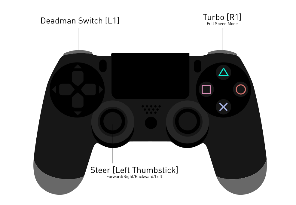
Both the PTZ camera and the driving lights can also be controlled through the controller. While holding the X button the left thumbstick controls the Pan and Tilt of the camera. While holding the O button the left thumbstick controls the zoom. The D-Pad is used to control the driving lights, with the top button controlling the front driving lights and the bottom button controlling the rear driving lights.
Using ROS
Robot Operating System (ROS) is an extensible framework for controlling and working with robotic systems. Clearpath Robotics recommends using ROS with your robot. If this is your first time using ROS, it is strongly recommended to run through our series of ROS tutorials to learn the basics of ROS.
System Networking Setup
Network Requirements
To monitor and control Husky Observer, it must be integrated into a communication network. The main requirements are:
- The user control device (tablet or laptop) must have network connectivity to the Husky Observer, either over a local Wi-Fi network or over the internet (eg. cellular connection to the robot).
- The user control device (tablet or laptop) must have access to the internet to be able to download map tiles. (In advanced modes, it is possible to create your own map to avoid this requirement.)
Network Modes
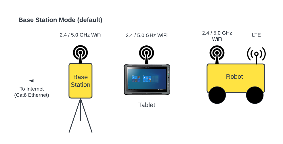
While there are many ways to meet the Network Requirements listed above, there are three common network modes for deploying Husky Observer, which are outlined below.
| Network Mode | Description | Base Station Setup | Robot Setup | Tablet Setup | OutdoorNav URL via Local WiFi | OutdoorNav URL via Internet/Cellular |
|---|---|---|---|---|---|---|
| Base Station | Base Station with WiFi for near-range operations; optional LTE also available on robot for long-range operations | Pre-configured at factory | Pre-configured at factory; see also Enabling LTE (Cellular) Networking on Robot for optional setup | Pre-configured at factory | http://192.168.132.1:8080 | See Remote Access Setup |
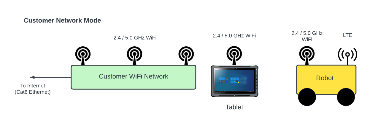
| Customer WiFi Network | Customer WiFi for near-range operations; optional LTE also available on robot for long-range operations | N/A | See Updating the WiFi SSID or Password on Robot; see also Enabling LTE (Cellular) Networking on Robot for optional setup | See Windows 10 instructions for connecting to Customer WiFi network | http://<customer_IP>:8080 | See Remote Access Setup |
| Cellular Only | Uses cellular in robot + separate cellular in Tablet | N/A | See Enabling LTE (Cellular) Networking on Robot for setup | Pre-configured at factory or use USB-tethering to a cell phone | N/A | See Remote Access Setup |
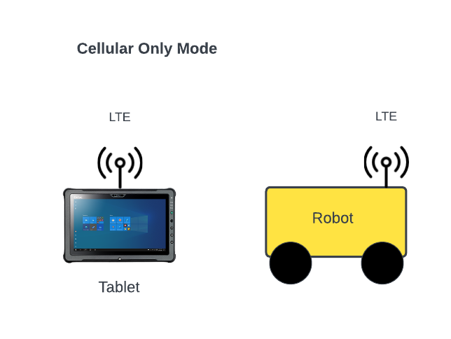
Cellular Only Mode
(
Some icons created by Freepik - Flaticon
)
Network Access Point Advanced Configuration
Both the robot and Base Station (if present) are equipped with a network access point that supports cellular, WiFi, and wired ethernet connections. These devices are pre-configured before shipping, but there are a small number of settings that the user may wish to adjust.
Configuring WAN/Internet Port on Base Station
To switch between DHCP and Static modes for the WAN/Internet port on the Base Station:
- Configure a wired Ethernet port on your laptop to
192.168.132.101/24. See Wired Network Connection for details. - Open the front panel of the Base Station and connect an Ethernet cable from the configured port on your laptop to one of the available LAN ports on the Microhard in the Base Station.
- Open the following in your Chrome browser: https://192.168.132.50/cgi-bin/webif/network-wan.sh
This should bring you to the "Network → WAN" menu. Note: Refer Appendix A for default credentials. - Update the "WAN2 Port Configuration" as desired.
- Click "Submit" in the bottom-right corner to apply the settings.
- Disconnect the Ethernet cable and close the Base Station.
Updating the WiFi SSID or Password on Base Station
The Base Station, if present, serves as a WiFi Access Point. Follow the steps below to change the default WiFi SSID or password of this access point.
- Configure a wired Ethernet port on your laptop to
192.168.132.101/24. See Wired Network Connection for details. - Open the front panel of the Base Station and connect an Ethernet cable from the configured port on your laptop to one of the available LAN ports on the Microhard in the Base Station.
- Open the following in your Chrome browser: https://192.168.132.50/cgi-bin/webif/wireless-wlan0.sh
This should bring you to the "Wireless → Radio1" menu. Note: Refer Appendix A for default credentials. - Update the "Radio1 Virtual Interface 1" to set the new SSID or password as desired.
- Click "Submit" in the bottom-right corner to apply the settings.
- Disconnect the Ethernet cable and close the Base Station.
- Apply the corresponding changes to the robot (see below).
Updating the WiFi SSID or Password on Robot
Using WiFi, the robot can connect to the Base Station, if present, or to a customer WiFi network. If the SSID or password on the Base Station has changed or if connecting the robot to a customer WiFi network, follow the steps below to match those of the WiFi access point.
- Configure a wired Ethernet port on your laptop to
192.168.131.101/24. See Wired Network Connection for details. - Connect an ethernet cable from the configured port on your laptop to the debug/expansion port on the top of the robot.
- Open the following in your Chrome browser: https://192.168.131.51/cgi-bin/webif/wireless-wlan0.sh
This should bring you to the "Wireless → Radio1" menu. Note: Refer Appendix A for default credentials. - Update the "Radio1 Virtual Interface 1" to set the new SSID or password to match that of the access point.
- Click "Submit" in the bottom-right corner to apply the settings.
- Disconnect the Ethernet cable.
Enabling LTE (Cellular) Networking on Robot
Where WiFi access is not available or when the robot will be travelling out of WiFi range, it is necessary to enable LTE (cellular) networking on the robot. Follow the steps below to enable LTE.
- Complete the physical Installation of SIM Card.
- Configure a wired Ethernet port on your laptop to
192.168.131.101/24. See Wired Network Connection for details. - Connect an ethernet cable from the configured port on your laptop to the debug/expansion port on the top of the robot.
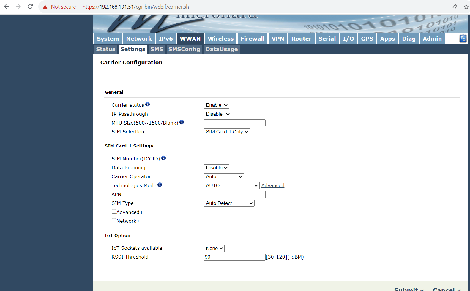
- Open the following in your Chrome browser: https://192.168.131.51/cgi-bin/webif/carrier.sh
This should bring you to the "WWAN → Settings" menu. Note: Refer Appendix A for default credentials. - Apply the following settings as shown in the image below:
- Carrier status:
Enable - IP-Passthrough:
Disable - MTU Size: (blank)
- SIM Selection:
SIM Card-1 Only - Data Roaming:
Disable - Carrier Operator:
Auto - Technologies Mode:
AUTO - APN: (carrier-specific)
- SIM Type:
Auto Detect - Advanced+: (not checked)
- Network+: (not checked)
- IoT Sockets available:
None - RSSI Threshold:
90
- Carrier status:
- After a couple minutes, check the WWAN status in your Chrome browser: https://192.168.131.51/cgi-bin/webif/carrier-status.sh
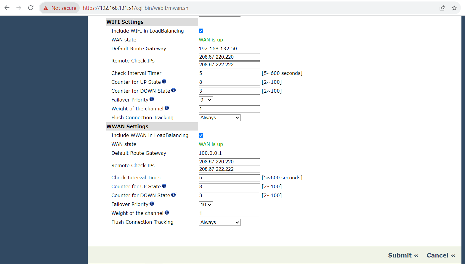
Ensure that "Activity Status" isConnectedand that a "WWAN IP Address" has been assigned. - Open the following in your Chrome browser: https://192.168.131.51/cgi-bin/webif/mwan.sh
This should bring you to the "Network → LoadBalancer" menu. - Confirm that the settings are as outlined in the figure below.
- Disconnect the Ethernet cable.
In some cases, it may be desirable to monitor the daily use on the WWAN interface, especially when there are monthly data limits for your SIM card. It is possible to review your daily and monthly usage on the WWAN interface from the Microhard "WWAN → DataUsage" menu: https://192.168.131.51/cgi-bin/webif/carrier-datausage.sh
It is possible to apply a bandwidth throttle, either to the WWAN or WiFi interface (or both). For OutdoorNav, any bandwidth limits would likely be applied to the upload direction to limit the amount of video data being sent from the robot; very little download data is used by the robot. To configure bandwidth throttling, use the Microhard "Network → Bandwidth" menu: https://192.168.131.51/cgi-bin/webif/thruputcontrol.sh
When cellular support is enabled on the robot, the system will automatically switch from WiFi to cellular if the WiFi connection has gone down for two minutes or more. This allows remote recovery of the robot if it has been driven beyond WiFi range.
When switching between WiFi and cellular modes, the switchover normally occurs within 30 seconds but may take up to 120 seconds to complete. In some cases, it may be necessary to refresh the OutdoorNav UI manually after the switchover.
Refer to the OutdoorNav User Manual for details on switching between WiFi and cellular modes.
Remote Access Setup
This step is optional. It is only for users attempting to access Husky Observer over the internet.
When attempting to access Husky Observer over the internet, it can sometimes be difficult to determine the IP address of the robot and to expose the necessary ports for access. Various services are available to simplify this remote access task. Once such service, ngrok, is described in detail below.
Remote Access via Ngrok
ngrok is an application that enables developers to expose a local development server to the internet with minimal effort. It can be leveraged to make the OutdoorNav User Interface (hosted on the Husky Observer robot) appear to be hosted on a subdomain of ngrok.com, meaning that no public IP or domain name on Husky Observer is needed. While the ngrok tools are pre-installed on Husky Observer, a small amount of configuration is required to use them.
- Sign up for ngrok if you don't yet have an account. The "Pro" tier is recommended.
- Configure a wired Ethernet port on your laptop to
192.168.131.101/24. See Wired Network Connection for details. - Connect an Ethernet cable from the configured port on your laptop to the debug/expansion port on the top of the robot.
- SSH to the robot:
ssh administrator@192.168.131.1. (See Appendix A for credentials.) - Ensure that the robot has internet access (eg.
ping 8.8.8.8). - Register your ngrok auth token (shown here) with the ngrok agent:
e.g.,ngrok config add-authtoken (your_auth_token) - Optional: Run a simple test to verify ngrok is working:
- Terminal 1:
python3 -m http.server - Terminal 2:
ngrok http 8000 - The ngrok terminal will display a remote address that you can enter, which should display the python3 HTTP server.
- Terminal 1:
- Select a subdomain name that will be used to access the OutdoorNav UI at https://your_subdomain.ngrok.io.
- Run
ngrok config editto set up a tunnel for your subdomain to port 80 on Husky Observer, where the OutdoorNav UI is running. These updates will be saved to:~/.config/ngrok/ngrok.yaml. Note that the example below includes a basic username/password authentication. Different authorization mechanisms are available. Refer to ngrok documentation for details.version: "2"
authtoken: your_auth_token
region: us
tunnels:
first:
addr: 80
proto: http
subdomain: your_subdomain
basic_auth: ["your_username:your_password"] - Check if ngrok is up and running by checking the ngrok agent page.
- Try to access the OutdoorNav UI at https://your_subdomain.ngrok.io.
While the example above shows how to forward port 80, it is possible to use ngrok to forward other ports as well, such as port 22 for SSH access. Simply add additional tunnels to the example above.
OutdoorNav Software Setup
Tablet Startup
The Husky Observer optionally ships with a Getac ruggedized tablet as shown in below.
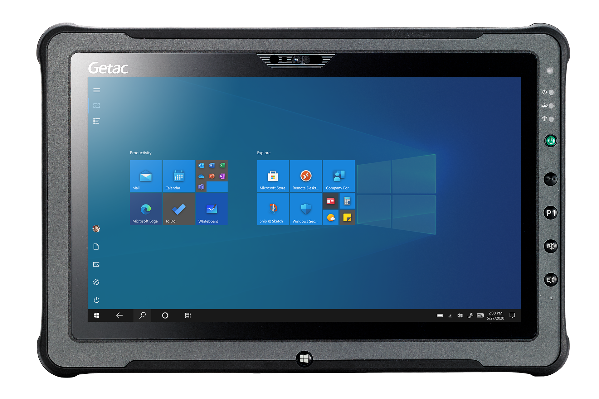
Power on the Getac ruggedized tablet by pressing the
GREEN power button on the right side of
the tablet. The tablet is running Windows 10 which will startup on power-up.
If prompted for a password, enter: clearpath.
Connecting to OutdoorNav Web User Interface
In order to connect to the OutdoorNav User Interface, ensure that the tablet has network connectivity to the Husky Observer as described in Networking Setup and note the URL for accessing the OutdoorNav UI.
- Open the Chrome browser.
- Enter the OutdoorNav UI URL in the search bar (see Network Modes for URLs).
- Optional: Add a bookmark to Chrome.
These steps will open the OutdoorNav UI, which will allow you to teleoperate and autonomously control the robot.
Loading Map Tiles
The OutdoorNav UI does not cache map tiles on the browser so you will need to connect to an internet source to load the map tiles. Ensure that your networking setup conforms to one of the supported Network Modes, to ensure that the tablet has network connectivity to both the robot and the internet.
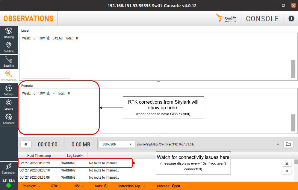
RTK Correction Setup
This step is optional, but highly recommended.
RTK corrections are used to minimize errors related to GPS-based localization and are strongly recommended when attempting to operate Husky Observer autonomously. If a Base Station is present, RTK corrections will be acquired from the Base Station, once it has been surveyed. Alternatively, RTK corrections can be acquired over the internet using the NTRIP protocol from various service providers, such as through the SwiftNav Skylark service. Both the Base Station and Skylark setup instructions are outlined below.
Survey Base Station
If a Base Station is present, it must be surveyed to be able to operate the robot autonomously. Follow the instructions in the OutdoorNav User Manual for details on how to survey the Base Station.
RTK Corrections via the Skylark Service
If a Base Station is not present, RTK corrections can be acquired over the internet using the NTRIP protocol. While various services are available for providing RTK corrections, Husky Observer has been validated with the SwiftNav Skylark service. Follow the steps below to set up the Skylark service.
- Sign up for a Skylark account if you do not have one. (Note that Clearpath does not provide a Skylark account.)
- Create a Skylark subscription (https://{your_account_name}.account.swiftnav.com/subscriptions) from the subscriptions tab.
- Create a new Device in the "Devices" tab corresponding to the robot that will be receiving the corrections.
- Configure the "position" SwiftNav Duro to communicate with the Skylark service.
- Ensure that the Swift Console is installed on your laptop.
- Configure a wired Ethernet port on your laptop to
192.168.131.101/24. See Wired Network Connection for details. - Connect an ethernet cable from the configured port on your laptop to the debug/expansion port on the top of the robot.
- Confirm that you can
ping 192.168.131.31, which validates network connectivity to the "position" Duro. - Open the Swift Console.
- "Connect to Device" using "TCP/IP" with "Host"
192.168.131.31and port55555.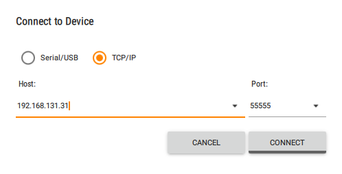
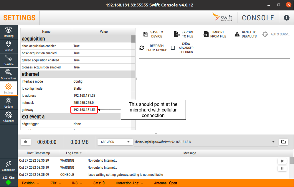
- In the "Settings" tab:
- Under "ethernet", set the "interface mode" to
Config. - Under "ethernet", set the "gateway" to
192.168.131.51, which is the IP address of network access point on the robot.
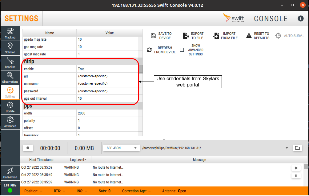
- Under "ntrip", set "enable" to
Trueand then fill in the remaining fields using the credentials from the Skylark web portal.
- Under "ethernet", set the "interface mode" to
- Click "Save to Device" to save the settings.
- In the "Settings" tab, under "ethernet", set the "interface mode" to
Active. - Click "Save to Device" to save the settings.
- In the "Observations" tab, confirm that RTK corrections from Skylark are being received.
- Disconnect the ethernet cable between your laptop and the robot.
Set Datum
Before being able to operate the robot autonomously, you will need to set the datum (ie. the reference point in the world coordinate frame). Follow the instructions in the OutdoorNav User Manual for details on how to set the datum.
Set Dock Location
Before being able to perform docking operations, you will need to set the dock location. Follow the instructions in the OutdoorNav User Manual for details on how to set the dock location.
If the Base Station has been moved (and therefore been resurveyed), or if the dock has been moved to a new location, you will need to set the location of the dock by repeating the above instructions.
OutdoorNav Operation
This section outlines how to operate the system through teleoperation as well as how to operate the system for autonomous missions, controlled by the OutdoorNav User Interface. Refer to the Outdoor Nav User Manual for details on the User Interface including: Main Components, Map View, Camera Views, and 3D View.
While this section outlines how to operate the robot using the User Interface, all functionality is also available through the Application Programming Interface (API). Refer to the Outdoor Nav User Manual for details on the API, including both an overview and a detailed listing.
Manual Mode (Teleoperation)
Ensure that you have read Safety and are aware of possible hazards when using this product as well as the safety methods that can be used to stop the moving robot.
Teleoperation allows the user to operate the robot remotely, using the built-in cameras. Refer to the Outdoor Nav User Manual for details on the Manual Mode (Teleoperation).
Autonomous Mode
Ensure that you have read Safety and are aware of possible hazards when using this product as well as the safety methods that can be used to stop the moving robot.
In autonomous mode, the user is able to create missions and then command the robot to execute those missions, without requiring user intervention during the execution of the mission.
Autonomous Missions
Refer to the OutdoorNav User Manual for details on the Autonomous Mode, including details on Autonomous Docking.
Retrieving Results from Autonomous Missions
During an autonomous mission, images, videos, audio, and other collateral may be captured and stored on the robot. At the end of the mission, these can be downloaded using an SFTP client that has network access to the robot. This connectivity could be from a device on the Base Station network (if present) or over the internet (where configured, see Remote Access Setup).
The IP address, username, and password for connecting to
the robot are provided in Appendix A: Networking Configuration.
The output files from the
autonomous missions are available to be downloaded from: /home/administrator/clearpath_files/media.
Key notes:
- In the above directory, there will be a subdirectory for each of the sensors.
Each of the sensor subdirectories will contain images, videos, or audio whose filenames
are based on the time at which the image was captured or the time at which the audio/video
recording was started. For example, a video that was
started on May 17, 2022 at 13:25:08 would correspond to a filename of:
2022-05-17_13-25-08.avi - The operator is responsible for deleting image, video, and audio files after they have been downloaded and archived. Failure to do so may result in the robot storage becoming full, which could prevent new mission data from being saved.
- Any SFTP-compatible client can be used to download the data. FileZilla, with details below, is the recommended SFTP client.
Using FileZilla for Downloading Data
FileZilla, available for free download, has a graphical user interface and is the recommended SFTP client.
The example below shows how to download files using the Base Station network.
If downloading via the internet instead, update the host below based on the
Remote Access Setup. For example, if using ngrok with a tunnel
set up on port 22 with a subdomain of customer1-sftp, then the host would
be customer1-sftp.ngrok.io and the port would be the one specified by
the ngrok mapping.
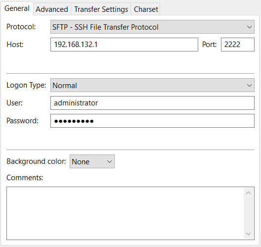
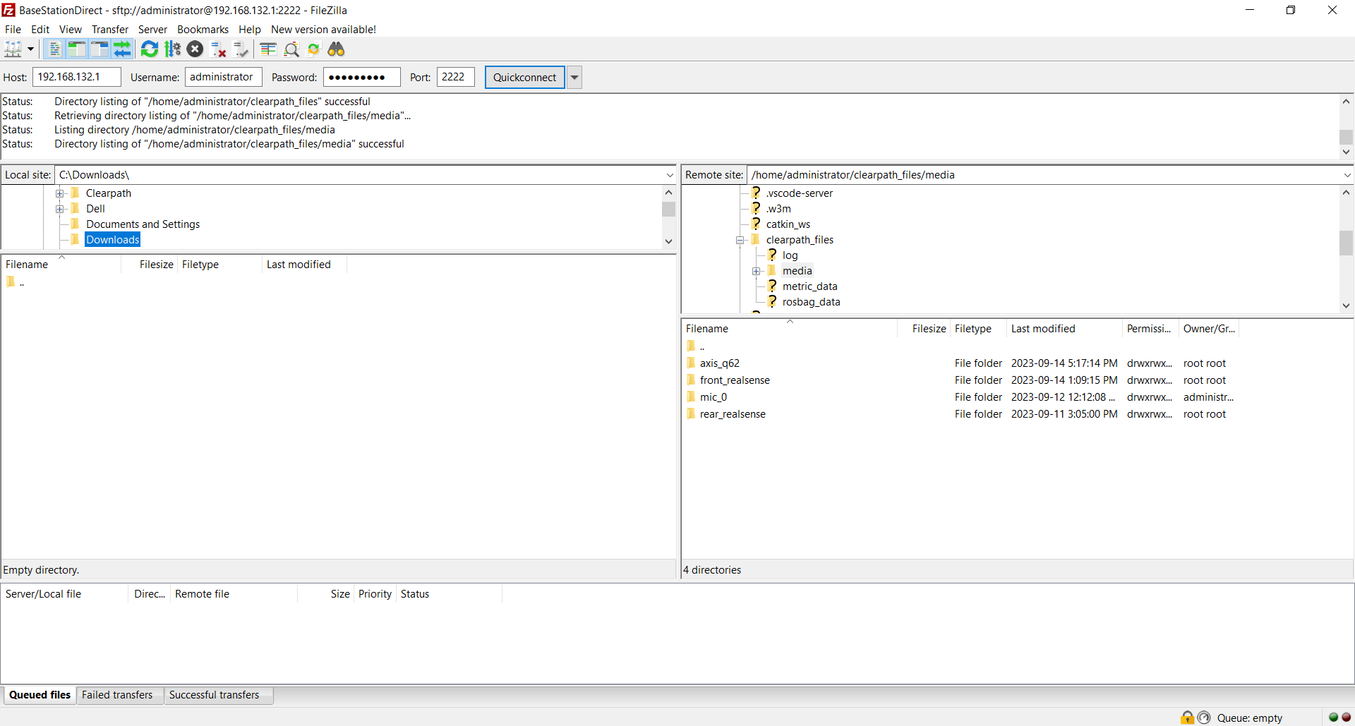
To use FileZilla on a laptop or tablet connected to the Base Station network, open FileZilla, use its menu to select File → Site Manager, and enter the settings as illustrated in the figure below and click "Connect".
- protocol: SFTP
- host: 192.168.132.1
- username: administrator
- password: clearpath
- port: 2222
To transfer files, use the local (left) and remote (right) file browsers as shown in the figure below. You can copy files off of the robot by selecting them on the right and dragging them to a folder on the left.
Once you are finished, close the connection with Server → Disconnect.
Monitoring System Status
The OutdoorNav UI has battery, networking, and status indicators on the main dashboard. In addition, to see the detailed status of the system in the OutdoorNav UI, select the "STATUS" option from the menu, which will provide the status for key subsystems:
- Localization
- Dock
- Wireless Charging
- System/Computer
- Sensors
All subsystems should have a green checkmark to indicate they are working as intended. Otherwise, a warning or error message is provided.
Using Pan-Tilt-Zoom Camera in Autonomous Missions
The Husky Observer is equipped with a pan-tilt-zoom (PTZ) camera that is capable of high zoom levels. During autonomous missions, pre-configured pan-tilt-zoom settings can be used to capture images and videos. These pan-tilt-zoom settings are configured through the Move PTZ Task. To increase the repeatability of data captured when using the Move PTZ Task, the Waypoint Heading should be enabled and Waypoint Tolerance settings should be set to their minimum values.
Even with these constraints, given the minimum tolerances and subject to environmental conditions, to ensure that images/videos captured following a Move PTZ Task are for an equivalent target area each time the mission is repeated, zoom values above the 25-40 are not recommended by default. Validation in the customer environment is recommended.
Support
Clearpath is committed to your success. Please get in touch with us and we will do our best to get you rolling again quickly: <support@clearpathrobotics.com>.
To get in touch with a salesperson regarding Clearpath Robotics products, please email <research-sales@clearpathrobotics.com>.
If you have an issue that is specifically about ROS and is something which may be of interest to the broader community, consider asking it on Robotics Stack Exchange. If you do not get a satisfactory response, please ping us and include a link to your question as posted there. If appropriate, we will answer on Robotics Stack Exchange for the benefit of the community.
Appendix A: Networking Configuration
Base Station Network WiFi Access
In some cases, it may be desirable to connect additional equipment, such as a laptop, to the Base Station network via WiFi. To do so, use the settings outlined below. By default, the Base Station is configured in DHCP mode; as such, the device being connected should be set for DHCP mode. Once connected to the Base Station, an IP address in the 192.168.132.0/24 will be assigned.
- Default WiFi SSID: CPR Base Station
- Default WiFi password: clearpath
Accessing the Main Computer from the WAN
All images and videos that are collected during missions are stored on the Main Computer inside Husky Observer until downloaded and deleted by the operator. When the download/delete function is performed by a computer within the Base Station network, the Main Computer can be accessed as described in the following section by connecting to TCP port 22 on the Main Computer. When the download/delete function is performed by a computer on the WAN network (connected to the Base Station WAN port), the operator can access the Main Computer by accessing TCP port 2222 on the Base Station, which gets mapped to TCP port 22 on the Main Computer.
Husky Observer Network Components
| Component | IP Address | Default Credentials |
|---|---|---|
| Main Computer | 192.168.131.1 10.252.252.100 | user: administrator password: clearpath |
| IndoorNav Computer (optional) | 10.252.252.1 | user: administrator password: clearpath |
| Camera, Axis, PTZ | 192.168.131.10 | user: root password: clearpath |
| Camera, FLIR, Thermal (optional) | 192.168.131.11 | user: administrator password: clearpath |
| 3D LiDAR, Velodyne | 192.168.131.20 | n/a |
| 2D LiDAR, Hokuyo, front | 192.168.131.21 | n/a |
| 2D LiDAR, Hokuyo, rear | 192.168.131.22 | n/a |
| GPS receiver, SwiftNav, Base Station (optional) | 192.168.131.30 | n/a |
| GPS receiver, SwiftNav, robot, right (position) | 192.168.131.31 | n/a |
| GPS receiver, SwiftNav, robot, left (heading) | 192.168.131.32 | n/a |
| Networking Gateway, Microhard, Base Station (optional) | 192.168.131.50 | user: admin password: clearpath |
| Networking Gateway, Microhard, robot | 192.168.131.51 | user: admin password: clearpath |
| Wireless Power Transmitter, WiBotic, dock | 192.168.2.20 | n/a |
| Tablet, Getac | 192.168.131.75 | user: administrator password: clearpath |
Appendix B: Advanced Configuration
Each of the sensors on Husky Observer has a variety of settings, which have been selected to work in a broad range of use cases. Certain specialized use cases may require the operator to create a custom configuration. The information below outlines the key settings for each sensor and where settings can be updated.
NOTE: Updating camera settings may affect overall system stability. Proceed with caution! Contact Support if you have any questions.
Axis PTZ Camera Configuration
The Husky Observer is equipped with an Axis Q62 series PTZ camera, with colour and low-light capabilities, defogger, and lens wiper.
Key Settings
- Resolution:
- Max: 1920x1080
- Default: 1280x720
- Frame rate:
- Max: 60 Hz
- Default: 20 Hz for data capture, 10Hz for UI live stream
Where to make adjustments
Global camera settings (like pan & tilt limits) can be set by logging into the Axis setup tool on the camera. Connect
a laptop to the robot and assign the laptop a static IP address of 192.168.131.101/24. Then open a
browser and navigate to http://192.168.131.10.
Resolution and frame rate settings can be adjusted on the Main Computer by editing the following environment
variables in /home/administrator/cpr_outdoornav_launch/env/sensors_customization.env. Note that any increase
in resolution may require a corresponding decrease in the frame rate to avoid data bottlenecks.
- AXIS_PTZ_WIDTH
- AXIS_PTZ_HEIGHT
- AXIS_PTZ_FPS
- AXIS_Q62_THROTTLE_RATE
Adjusting Pan Limits
The Axis Q62 is normally capable of making continuous rotations in either direction. This allows the camera to always take the shortest trajectory to reach any given pan angle. However, if you have additional equipment mounted on top of the camera, for example a Flir thermal camera or a microphone, this behaviour may cause the wires to get tangled around the PTZ camera and potentially cause damage to the robot.
To prevent damage to the robot, the camera has been pre-configured with pan limits on the Axis camera. This will restrict the camera's range of motion to less than 180 degrees in either direction, eliminating the risk of the camera making continuous rotations.
The steps below outline how to adjust the pan limits.
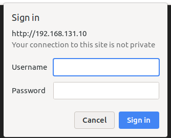
Connect your laptop to one of the robot's exposed ethernet ports and assign your laptop a static
IP address of 192.168.131.101/24. Open your web browser and navigate to
http://192.168.131.10. Log into the Axis configuration website using the credentials found
in Appendix A.
In the browser, click on Settings and select PTZ
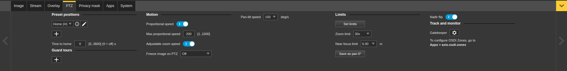
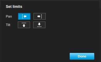
Disable any exisitng pan limits by opening the limits menu and making sure all the buttons are off.
Move the camera to a pan of -179 degrees. The easiest way to move the camera precisely is to launch the ROS driver on the Main Computer and use the cmd topic to move the camera.
Note that the driver expects the pan and tilt angles to be in radians.
# Start the driver in one terminal
# Replace the IP address as appropriate for your camera
roslaunch axis_camera axis.launch enable_ptz:=true username:=root password:=clearpath hostname:=192.168.131.10

# In a second terminal, run
rostopic pub /axis/cmd/position axis_msgs/Ptz "{pan: -3.12414, tilt: 0.0, zoom: 1.0}" -1"
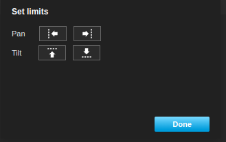
Once the camera finishes moving, set the left pan limit by pressing the left limit button:
Then move the camera to a pan of 179 degrees:
rostopic pub /axis/cmd/position axis_msgs/Ptz "{pan: 3.12414, tilt: 0.0, zoom: 1.0}" -1"
Once the camera finishes moving, click on the right pan limit button to set the right pan limit to 179 degrees.
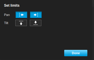
Click the Done button to apply the new limits. Note that the camera will now have a 2-degree deadzone at the rear where it cannot point. This is an unfortunate but unavoidable side-effect of setting the limits this way.
::: note
In version 0.5.0 onward the axis_camera ROS driver uses radians instead of degrees. If you have an older version of the driver
installed, you can set the pan angles with this command instead:
rostopic pub /axis/cmd axis_camera/Axis "{pan: 179.0, tilt: 0.0, zoom: 1.0, focus: 0.0, brightness: 1.0, iris: 0.0, autofocus: true, autoiris: true}" -1
:::
RealSense Front and Rear Rear Driving Camera Configuration
Key Settings
- Resolution: 854x480
- Frame rate: 6 Hz
Where to make adjustments
The front/rear camera settings are not configurable.
Motion Buzzer Enable/Disable
The system is equipped with a buzzer to produces a loud sound when the system is driving in any direction. This buzzer is enabled by default. To disable the buzzer, run the following command on the Main Computer:
rosservice call /safety_alarm/set_mute "data: true"
Omnidirectional Microphone Configuration
No configuration is available for the omnidirectional microphone.