Husky Observer Integration
To attach custom hardware to Husky Observer, you will have to take care of mechanical mounting, electrical supply, and software integration. This guide aims to equip you with respect to these challenges.
Mechanical Mounting
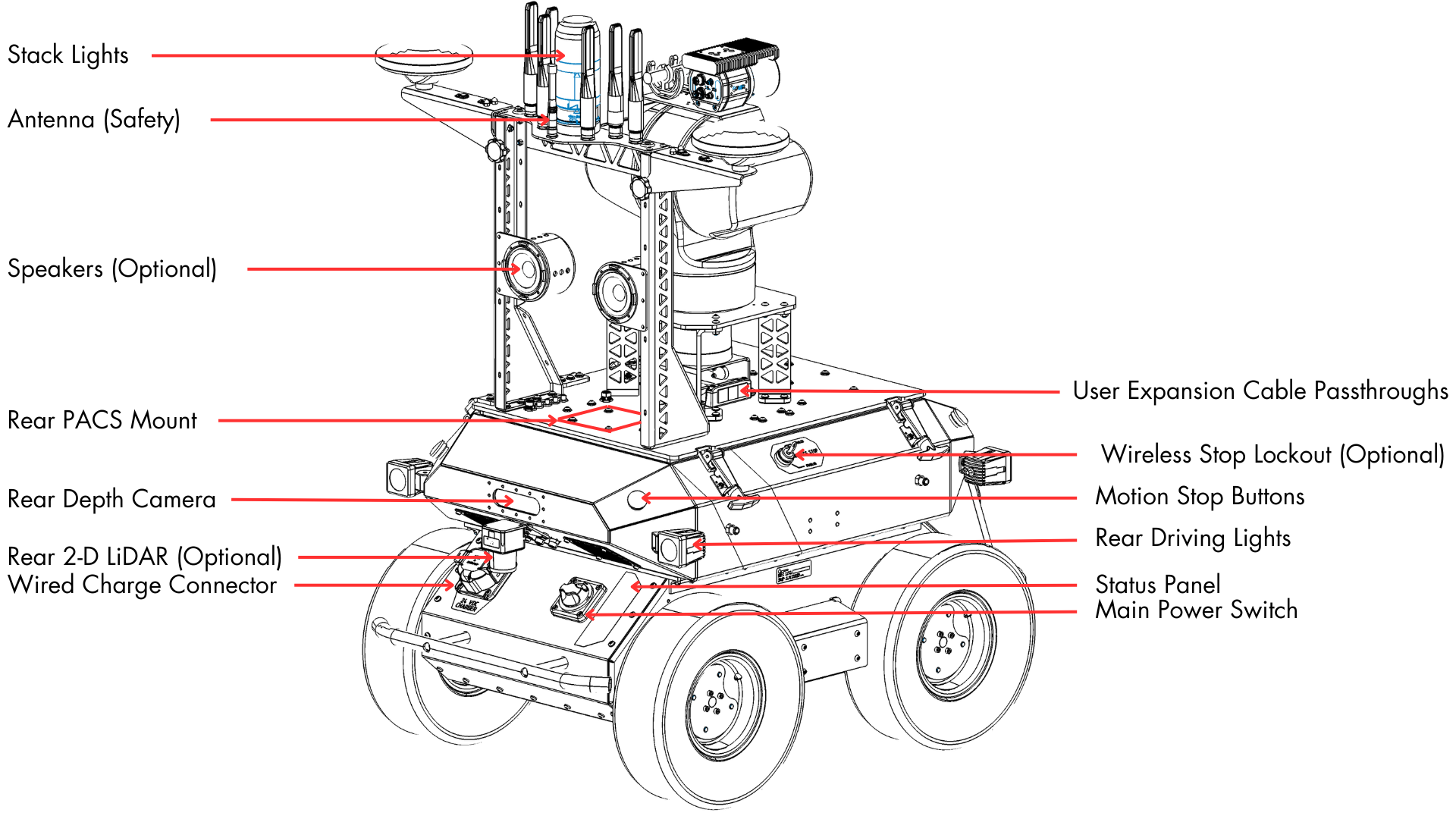
Husky Observer has two PACS™-compatible mount points on the top of the robot, one at the front and one at the rear, as outlined in the figures below. Each of the two mount points can support a payload up to 5 kg.
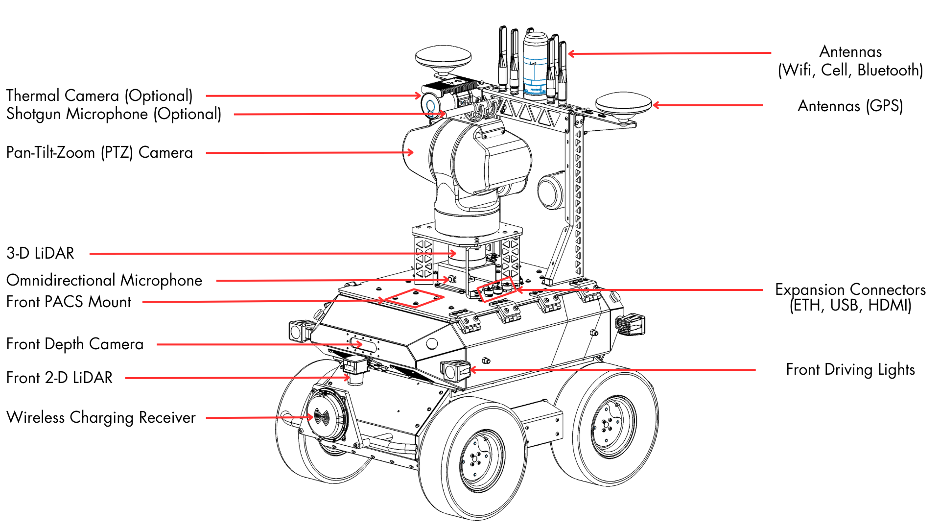
PACS™ is a Clearpath Robotics standard. We add a grid of M5x0.8 holes onto the top plate of the robot. This grid of holes has a 80 mm X 80 mm spacing. You can create your own brackets to interface with these holes, or can use an existing Clearpath Robotics designed bracket.
Our Sensors and Accessories pages indicate the required bracket for the particular attachment.
When using the front and rear mount point, be careful to avoid blocking the field of view of the 3D LiDAR. If you have any related questions, please contact Support.
Electrical Integration
Except for bus-powered USB cameras, most payloads have separate leads for power and data.
Maintenance and Debugging Connections
On the Husky Observer lid, there are three data interfaces that can be used for system maintenance and debugging:
- One 1 Gbps Ethernet (RJ45 connector), connected to the Main Computer
- One USB 3.0 (Type A connector), connected to the Main Computer
- One HDMI, connected to the Main Computer
Custom Payload Connections
On the Husky Observer lid, there is an Icotek KEL-FG-ER-E3 connector with three cable glands that will allow the user to create and route power cables from custom payloads on the lid to power sources inside the Husky Observer while still maintaining the IP rating of the robot. (See this video for more details on using the Icotek cable glands system.)
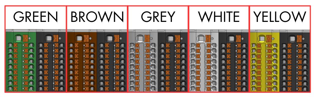
Inside the Husky Observer, power is available from terminal blocks as outlined in the table below. For each power source, 18 AWG wires with ferrules (DigiKey P/N 277-2156-ND) are recommended for power cables at the end that gets inserted into the terminal blocks. Note that positive and negative wires are connected to separate terminal blocks.
| Power Source | Maximum Current | Terminal Blocks |
|---|---|---|
| VBAT (24.0 V minimum) | 3.75 A | Brown (positive), Black (negative) |
| 24 V | 2.5 A | Grey (positive), Black (negative) |
| 12 V | 3.5 A | White (positive), Black (negative) |
In addition to the power connections, the cable glands can be used to make data connections to available ports on the Ethernet switch or to available USB ports on the Main Computer. When connecting a device to the Ethernet switch, the device should be configured with a static IP address in the 192.168.131.80 to 192.168.131.89 range.
Software Integration
ROS has a large ecosystem of sensor drivers, some of which include pre-made URDF descriptions and even simulation configurations. Refer to Sensors supported by ROS.
For the best experience, consider purchasing supported accessories from Clearpath Robotics for your robot, which will include simulation, visualization, and driver support.
Refer to the following for more details:
Support
Clearpath is committed to your success. Please get in touch with us and we will do our best to get you rolling again quickly: <support@clearpathrobotics.com>.
To get in touch with a salesperson regarding Clearpath Robotics products, please email <research-sales@clearpathrobotics.com>.
If you have an issue that is specifically about ROS and is something which may be of interest to the broader community, consider asking it on Robotics Stack Exchange. If you do not get a satisfactory response, please ping us and include a link to your question as posted there. If appropriate, we will answer on Robotics Stack Exchange for the benefit of the community.