Web UI Overview
The Web User Interface (Web UI) provides an easy, graphical, means to control both manual and autonomous operation of your UGV. The following sections outline: the components and views of the UI, the details of operating in manual mode, and the details of operating in autonomous mode.
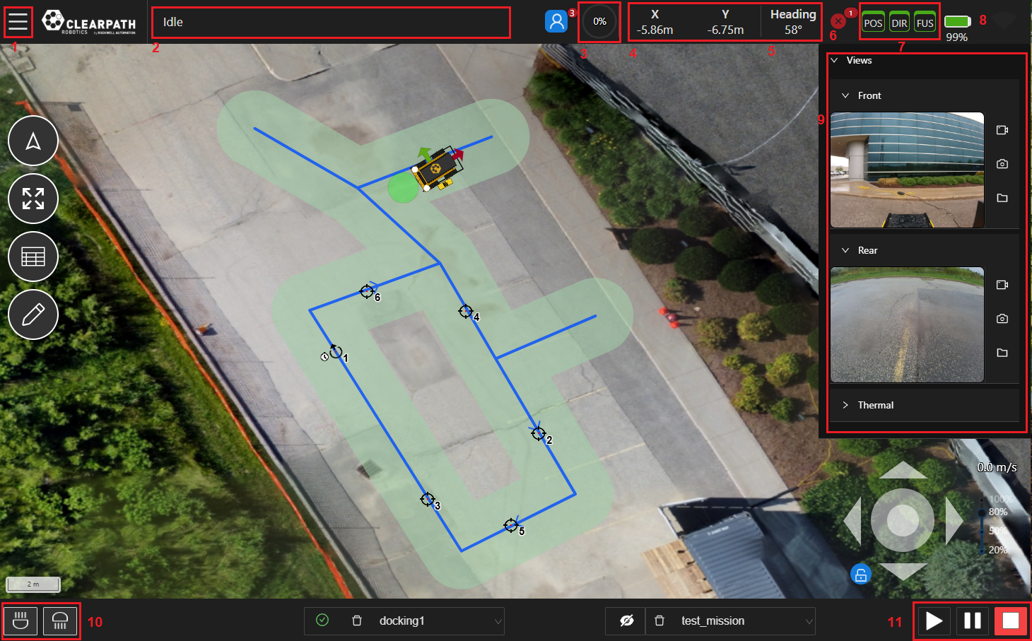
Main Components
-
Menu: A dropdown menu allowing the user to access the Dashboard (ie. Home), File, Settings, Autonomy, Tools, and Help.
-
Feedback Bar: The feedback bar will display information regarding the execution state of the navigation and of any Tasks being executed.
-
Path Progress Meter: A meter indicating the percentage complete of a Mission.
-
UGV Position: The UGV's X and Y position in the world frame relative to the Datum. Can also be shown in Lat/Lon coordinates
-
UGV Heading: The UGV's heading in the world frame. 0 degrees is North, 90 degrees is East, 180 degrees is South and 270 degrees is West.
-
Status Indicator: The status indicator will display information regarding various UGV status monitors such as the Emergency Stop, Surveying, etc. When the UGV is fully operational, the indicator will be green. Operators can click on the status indicator to see more details pertaining to the current state as well as past messages.
-
GPS Status Indicator: The GPS status indicators will display GPS signal accuracy for position (POS indicator), heading (DIR indicator), and sensor fusion (FUS indicator). Green indicators represent RTK accuracy and are currently required for accurate autonomous navigation. Yellow and orange indicators represent SBAS and SPP accuracy respectively and noticeable oscillations may occur in such cases. Red indicators mean no GPS signal and autonomous navigation missions should not be started.
-
Battery Life Indicator: The UGV's battery life indicator.
noteIf the indicator is stuck at 50%, that means that your UGV does not have a supported battery management system and this indicator is not active.
-
Views List: A dropdown list of available views, detailed later in this section. Some of the available views are Map, and Camera views etc.
-
Lights Control: If the UGV is equipped with software controllable lights they can be controlled here.
-
Mission Execution Buttons: These buttons allow users to Start, Pause and Stop an autonomous mission.
By opening the dropdown list "Views", on the right side of the UI, the Operator can access the following views:
- Map View
- PTZ Camera View (if available)
- Front/Back Camera View (if available)
Map View
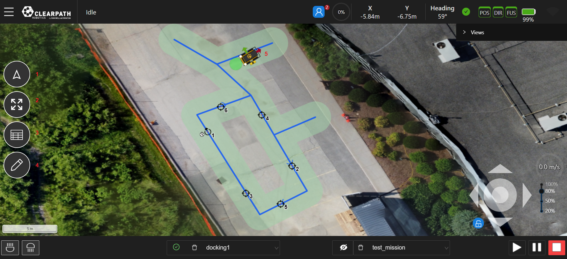
- Zoom-to-Robot Button: This button will zoom the map to where the UGV is presently located.
- Zoom-to-Fit Button: This button will zoom the map to where there is activity (ie. where the datum is set or where features have been set on the map.)
- Table Button: This button opens the Map/Mission table. When in Waypoint Mode it will open the table directly, while in Map mode it will allow users to select the table to open or open a table based on which mode is being edited.
- Edit Mode Buttons: This button will allow the user to set the current map edit mode.
By clicking the button, a panel opens on the right with the available modes to edit with.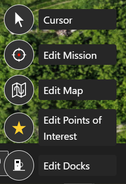
Edit Modes - UGV + Dock: The robot represents the UGV position, with the red arrow pointing forward. Its location is its position in the world frame and its orientation is the heading in the world frame.
- Datum (not shown): The blue Waypoint marker on the map view represents the location of the reference point (ie. (x,y)=(0,0)) of the world coordinate system. The world (ie. map) coordinate system is in the ENU convention.
Camera Views
If PTZ and/or Front/Back camera(s) are included on the UGV, their feeds can be viewed through the UI and the PTZ can be controlled through the UI. If not, there will not be any PTZ, Front/Back view(s) in the list of available views.
Pan-Tilt-Zoom (PTZ) View
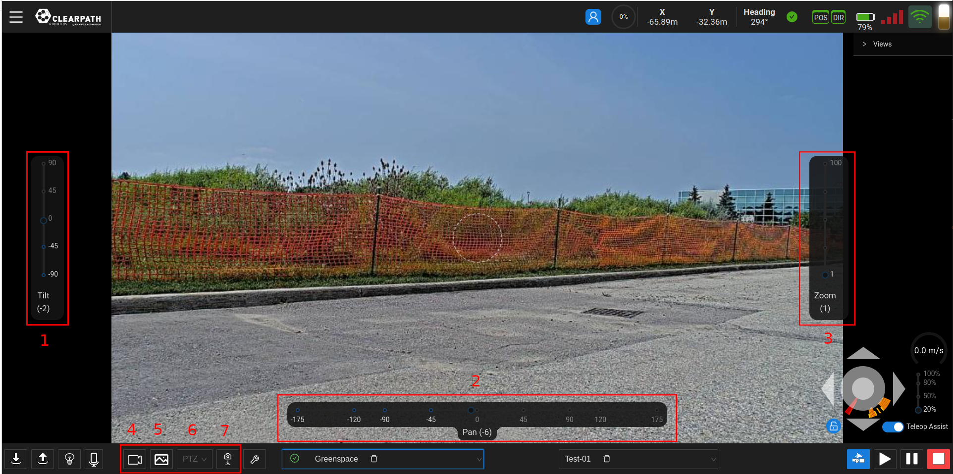
- Tilt Slider: The left slider can be used to tilt the camera in a vertical motion, (ie. upwards or downwards motion). By default, the slider is at its neutral ("zero") position.
- Pan Slider: The bottom slider can be used to pan/rotate the camera, (ie. rotational motion). By default, the slider is at its neutral ("zero") position.
- Zoom Slider: The right slider can be used to zoom the camera feed. By default, the slider is at its neutral ("zero") position.
- Start/Stop Recording: This button will start/stop video recording for the camera and store the video file on the UGV.
- Save Image: Depending on the current camera view selected, this button will save an image to the computer/tablet running the UI. Images will be saved to the location in which your browser saves files.
- Camera Positions List: Deprecated feature.
- Save Camera Position: Deprecated feature.
Q62 PTZ Features
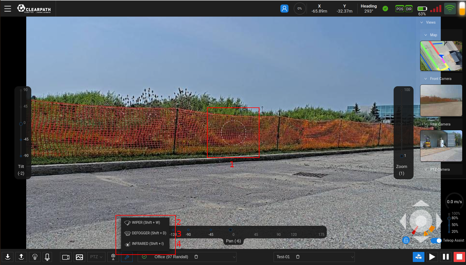
- Virtual PTZ Joystick: This joystick can be dragged away from the center of the screen and the camera will follow. The further away from the center the user drags the joystick, the faster the camera moves.
- Q62 Wiper: Future feature.
- Q62 Defogger: Future feature.
- Q62 Infrared: Future feature.
The Q62 PTZ Camera has the ability to move the camera in other ways besides the sliders on the screen. Some of these are shown below in brief video clips.
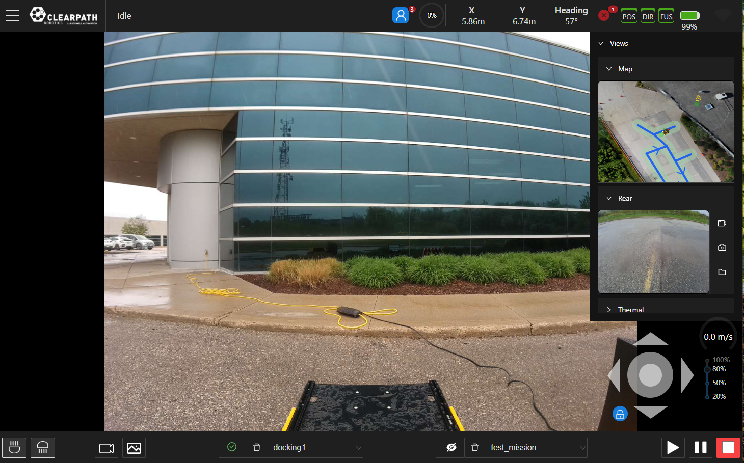
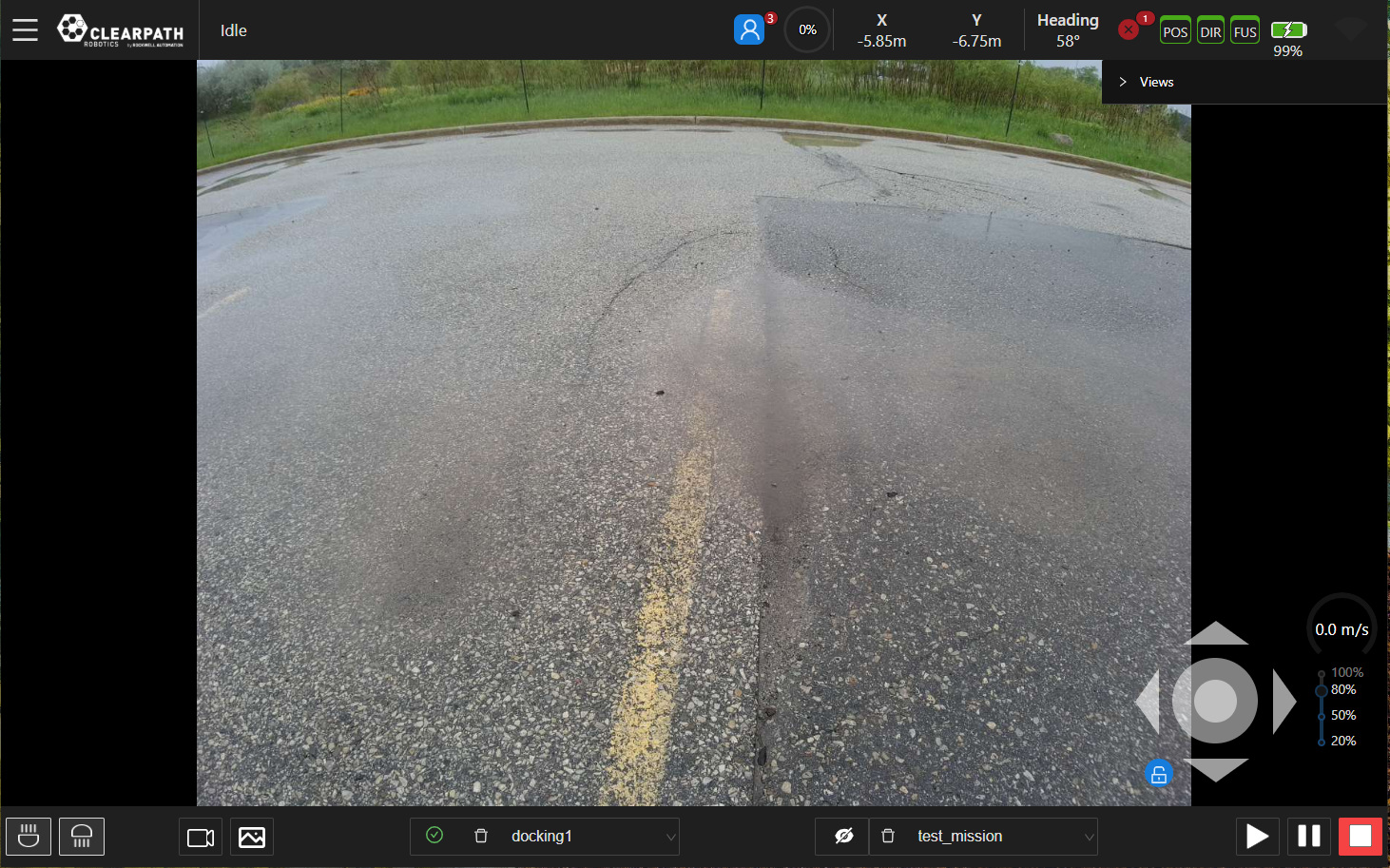
Front and Back Views
Settings
The settings section can be found accessing Menu → SETTINGS and allows the user to modify some settings, both for the UI and the UGV.
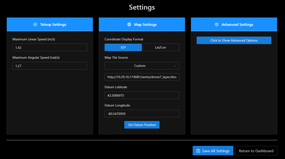
Teleop Settings
Maximum Linear Speed
The maximum linear speed (forwards/backwards) at which the robot will be allowed to operate.
Maximum Angular Speed
The maximum speed at which the robot will be allowed to turn.
Map Settings
Coordinate Display Format
The Operator can change the coordinate space from X/Y relative to the Datum to Latitude/Longitude.
Map Tile Source
Select between OpenStreetMap, MapBox, and Custom map tiles.
The Web UI ships with access to free OpenStreetMap maps. Aerial view requires access to third-party aerial maps or your own aerial maps.
The Web UI is pre-configured for use with MapBox once a suitable map key has been acquired. It offers a free tier that will be sufficient in almost all cases.
Using OpenStreetMap Maps
No key is required to use OpenStreetMap maps.
Using MapBox Maps
Using MapBox maps requires a key, which can then be used by the Web UI.
- Acquire a MapBox key from the MapBox website. Review the license terms and select the appropriate plan. In most cases, the free tier will be sufficient.
- Back in the Web UI, select MapBox.
- Copy the MapBox key from Step 1 into the input box.
- Click Save All Settings.
Using Custom Maps
Custom Maps allow you to use another set of maps in XYZ format, either from a third-party map provider or from maps that you have generated on your own, such as from drone aerial images. Custom maps can be selected by using the steps below.
- Ensure that the maps are accessible on an internal network or on the Internet by the device that is being used to display the Web UI, such as a laptop, tablet, or desktop computer.
- Ensure that the directory structure for the individual tiles is well defined. See the section below for details on Preparing Custom Map Tiles from Drone Aerial Images.
- In the Web UI, select Custom.
- Enter the network path for the maps into the Custom URL field.
If hosting the maps on your local computer, this will be similar to
http://localhost:8000/{z}/{x}/{-y}.png. Note how the
URL is parameterized with
{z},{x}, and{-y}values. This will need to be adapted to match the directory structure of your map tile images. - Click Save All Settings.
Preparing Custom Map Tiles from Drone Aerial Images
In some cases, it is desirable to create your own maps rather than using third party maps which might be outdated. One way to do this is to use a drone to capture aerial images and convert those images into map tiles. While there are many ways to accomplish this, one approach is outlined below.
-
Use a drone to collect top-down photos covering the area of interest. It is highly recommended to use a drone control app that allows you to specify the area of interest and desired image overlap (recommended ~75%) and takes care of coverage planning, drone control, and image acquisition.
-
Perform ortho-mosaicing/ortho-rectification to stitch the collected images together into a single orthographic image. Open Drone Map is a popular open source project that Clearpath has used for stitching, but there are also paid services that automate the process.
-
Georeference the orthographic image. One way to do this is to define the locations of well-defined features (sewer grates, utility holes, etc.) based on their known positions, such as their position data from an existing mapping service (e.g., Google Maps). Open source tools, such as QGIS can help with this process.
-
Generate the map tiles. Using Ubuntu, this can be accomplished with the following commands, where
GEOREFERENCED_IMG.tifis the output of the previous step.sudo apt install gdal-bin
gdal2tiles.py <GEOREFERENCED_IMG.tif> -
Use a web server to host the tiles locally. Using Ubuntu, one way to accomplish this is to use the commands below, which will make the tiles available at: <http://localhost:8000/\>.
cd /base/directory/of/tiles
python3 -m http.server
Once your map tiles are available on the network, you can follow the steps in Using Custom Maps to have the Web UI use your custom tiles.
Datum Latitude, Datum Longitude
The datum is represented by a blue marker on the map and should be set to a location within 10km of the test site. The user can change this value. Enter the new values and click the "Set Datum Position" button.
Advanced Settings
Only adjust these settings if advised to by Support.
Autonomy Features
To operate the UGV autonomously, use Map Mode.
The key features of Map Mode are outlined below.
Tasks
When running a mission autonomously the user can assign tasks to various events. These tasks, along with their decoration icons, are found below:
-
 Dock Robot:
Will dock the UGV to begin charging the UGV's battery.
Dock Robot:
Will dock the UGV to begin charging the UGV's battery. -
 Move PTZ:
Will move the PTZ camera to the position selected in the task settings.
Move PTZ:
Will move the PTZ camera to the position selected in the task settings.Settings: Select the camera position. See Pan-Tilt-Zoom (PTZ) View for details on how to save camera positions.
-
 Save Image:
Will save an image using one of the UGV camera(s) to the /opt/onav/saved_files/media/... directory and can be retrieved using a tool such as FileZilla or by navigating to the Files section in the hamburger menu.
Save Image:
Will save an image using one of the UGV camera(s) to the /opt/onav/saved_files/media/... directory and can be retrieved using a tool such as FileZilla or by navigating to the Files section in the hamburger menu.Settings: Select which camera the image will be saved from.
-
 /
/
 Start/Stop Video Recording:
Will start/stop recording video using one of the UGV camera(s) to the /opt/onav/saved_files/media/... folder and can be retrieved using a tool such as FileZilla or by navigating to the Files section in the hamburger menu.
Start/Stop Video Recording:
Will start/stop recording video using one of the UGV camera(s) to the /opt/onav/saved_files/media/... folder and can be retrieved using a tool such as FileZilla or by navigating to the Files section in the hamburger menu.Settings: Select which camera the recording will come from.
-
 Start/Stop Audio Recording:
Will start/stop recording audio using one of the UGV microphone(s) to the /opt/onav/saved_files/media/... folder and can be retrieved using a tool such as FileZilla or by navigating to the Files section in the hamburger menu.
Start/Stop Audio Recording:
Will start/stop recording audio using one of the UGV microphone(s) to the /opt/onav/saved_files/media/... folder and can be retrieved using a tool such as FileZilla or by navigating to the Files section in the hamburger menu.Settings: Select which microphone the recording will come from.
-
 Undock UGV:
Will undock the UGV from the autocharge dock. Once completed, the UGV can be sent on autonomous missions.
Undock UGV:
Will undock the UGV from the autocharge dock. Once completed, the UGV can be sent on autonomous missions. -
 Wait:
Will pause and wait for the specified number of seconds at the end of the Waypoint.
Wait:
Will pause and wait for the specified number of seconds at the end of the Waypoint.Settings: Enter the amount of time to wait, in seconds.
-
 Inspect POI:
Will move the PTZ camera to inspect a specified Point of interest.
Inspect POI:
Will move the PTZ camera to inspect a specified Point of interest.Settings: Select the inspectable Point of Interest and enter in the zoom level to use.
-
 New Custom Task:
Creates a new custom task that is defined by the user.
New Custom Task:
Creates a new custom task that is defined by the user.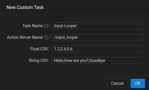
Custom Task Settings Dialog - Task Name: Task name that will show up in the list of available tasks on the UI.
- Action Server Name: The namespace of the custom task action server.
- Float CSV: A list of comma seperated float values that consist of the numerical inputs to the custom task.
- String CSV: A list of comma seperated string values that consist of the semantic inputs to the custom task.
If a Waypoint/Goalpoint has more than one task assigned to it, the icon will
be replaced with a sheet of paper icon like so: 
Points of Interest
Points of Interest (POI) can be added onto the map, marking a location or an object that is persistent. The intended use for the points of interest feature is to allow the user to set up locations that they know will almost never change and to be able to navigate to and inspect these locations.
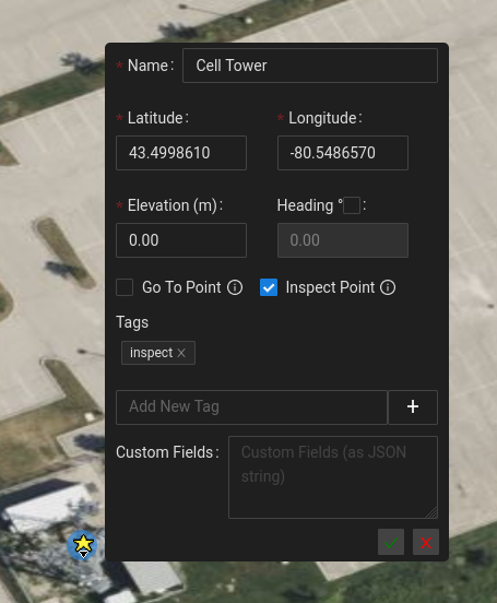
Creating POIs
To create a POI, ensure that you are in "POI edit mode" (Hotkey, e+4). Click on the map to place your POI and assign the POI a name. You also have the ability on creation to assign a heading, tags and custom fields (all optional).
Editing POIs
To edit an existing POI, right click the POI and select Edit. This will allow you to modify any of the existing properties of the POI. If you want to simply modify the heading of a POI, you can use the CTRL hotkey to enable heading modification and rotate the POI to your desired heading. See video below for an example of the editing the heading of a POI using the (CTRL hotkey).
Predefined actions
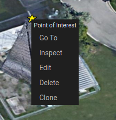
If a POI is assigned one of the two predefined tags, goto and/or inspect, the user will have the ability to perform
some quick actions when they right click the POI. If the POI has a goto tag,
the user will see a Go To option in the right click options that will autonomously navigate the UGV to the location of
the POI (if it is within the bounds of the current network). If the POI has an inspect tag, the user will see an Inspect
option in the right click options that will move the PTZ camera to view the POI when clicked. See the below image for an
example of a POI that has both the goto and inspect tags, and therefore has the Go To and Inspect action options
when right clicked.
Creating Missions from POIs
If the user wants your UGV to navigate to a set of predefined locations they can create POI's for each of these stops and leverage them accordingly. By entering the network mission edit mode (hotkey: e+3), the user can simply click on the POIs in order of traversal to create your network mission. The network goals that are created on each click of a POI will place a Goal at the exact location of the POI and will also use the heading that has been defined by the POI.