Boxer Integration
To attach custom hardware to Boxer, you will have to take care of mechanical mounting, electrical supply, and software integration. This guide aims to equip you with respect to these challenges.
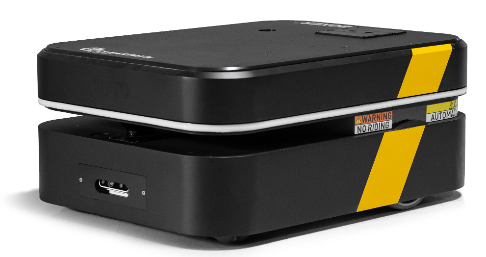
Mechanical Mounting
When determining mechanical mounting, you can use the Standard mounting pattern on the top plate of the Boxer. At this time, the "PACS™" mounting system is not available for Boxer.
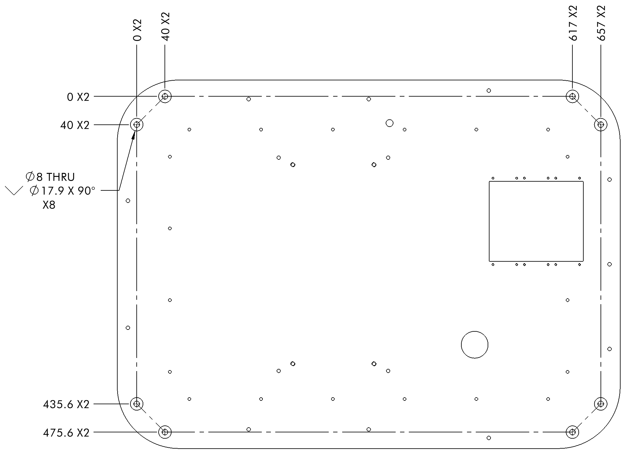
Mechanical, Standard
External payloads can be attached to the mounting plate of the Boxer by using the Ø8 mm countersunk through holes on the underside, or adding new holes. Whichever method you choose, the method for removing the top plate is the same and outlined below.
- Ensure the robot is shut off, and the circuit breaker is turned to the off position.
- Disconnect and remove all existing payloads on the top plate.
- Using a 2 mm hex key, remove the twelve M3 round head screws holding the connection covers in place. Remove the panels. Take care to disconnect the network cable and attachment cable from the robot when removing the connection covers.
- Using a 4 mm hex key, remove the eleven M5 socket head screws holding the plate down.
- Remove the plate from the Boxer.
The Boxer plate is made from 8 mm aluminum and can be easily machined according to your customization needs.
The plate also has eight Ø8 mm holes in the corners which are countersunk from the underside of the plate, making them ideal for flathead screws installed to protrude from the plate.
Electrical Integration
For connecting with any external payloads, such as a backpack computer, refer to the product's datasheet or manual. If your robot was equipped with these payloads by Clearpath Robotics this documentation is provided along with your Boxer. Contact Support if you need more information.
Ensure that the Boxer is shut off and the circuit breaker is turned to the off position before performing any electrical work on the Boxer.
The Boxer is equipped with an attachment interface that consists of a Power-over-Ethernet (PoE) RJ45 bulkhead connector, a USB Type-A bulkhead connector, and a 37-position panel receptacle and mated plug. To connect with the Boxer attachment interface see Section 10 of the OTTO 100 V2.5 Operation and Maintenance Manual.
To add wires to the 37-position connector for you application, follow the TE Connectivity documentation for connector 206305-1 to use appropriate crimp pins. Note that the 37-position connector will come pre-populated from Clearpath Robotics with 2 wires. These 2 wires complete the base Boxer's Motion Stop loop, allowing the robot to move. Other positions of the connector may be pre-populated, well as the PoE and USB, if your robot was equipped with payloads according to your Clearpath Robotics customizations.
Software Integration
ROS has a large ecosystem of sensor drivers, some of which include pre-made URDF descriptions and even simulation configurations. Refer to Sensors supported by ROS.
For the best experience, consider purchasing supported accessories from Clearpath Robotics for your robot, which will include simulation, visualization, and driver support.
Refer to the following for more details:
Support
Clearpath is committed to your success. Please get in touch with us and we will do our best to get you rolling again quickly: <support@clearpathrobotics.com>.
To get in touch with a salesperson regarding Clearpath Robotics products, please email <research-sales@clearpathrobotics.com>.
If you have an issue that is specifically about ROS and is something which may be of interest to the broader community, consider asking it on Robotics Stack Exchange. If you do not get a satisfactory response, please ping us and include a link to your question as posted there. If appropriate, we will answer on Robotics Stack Exchange for the benefit of the community.