Sensors
At Clearpath, we have been migrating our large inventory of tested sensor drivers from ROS 1 to ROS 2.
Sensors are split up into sections:
- Cameras publish sensor_msgs/Image messages
- GPS publish sensor_msgs/NavSatFix messages
- IMU publish sensor_msgs/Imu messages
- LiDAR 2D publish sensor_msgs/LaserScan messages
- LiDAR 3D publish sensor_msgs/PointCloud2 messages
- PTU publish sensor_msgs/JointState messages
In ROS 2, sensors use a ros_parameters YAML that contains all launch parameters for the driver node. To facilitate complete customization of these node parameters, the ros_parameters section, under every sensor entry, serves as a way to pass those key-value pairs to the corresponding node.
By default, we pass tested parameters that are used on Clearpath robots.
Sample
Sample A200 Sensors Section

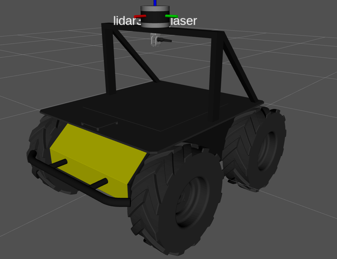
In this sample, we first add the velodyne_lidar to the sensor_arch_mount by simply changing the parent link.
lidar3d:
  - model: velodyne_lidar
    urdf_enabled: true
    launch_enabled: true
    parent: sensor_arch_mount
    xyz: [0.0, 0.0, 0.0]
    rpy: [0.0, 0.0, 0.0]
    ros_parameters:
      velodyne_driver_node:
        frame_id: lidar3d_0_laser
        device_ip: 192.168.131.25
        port: 2368
        model: VLP16
      velodyne_transform_node:
        model: VLP16
        fixed_frame: lidar3d_0_laser
        target_frame: lidar3d_0_laser
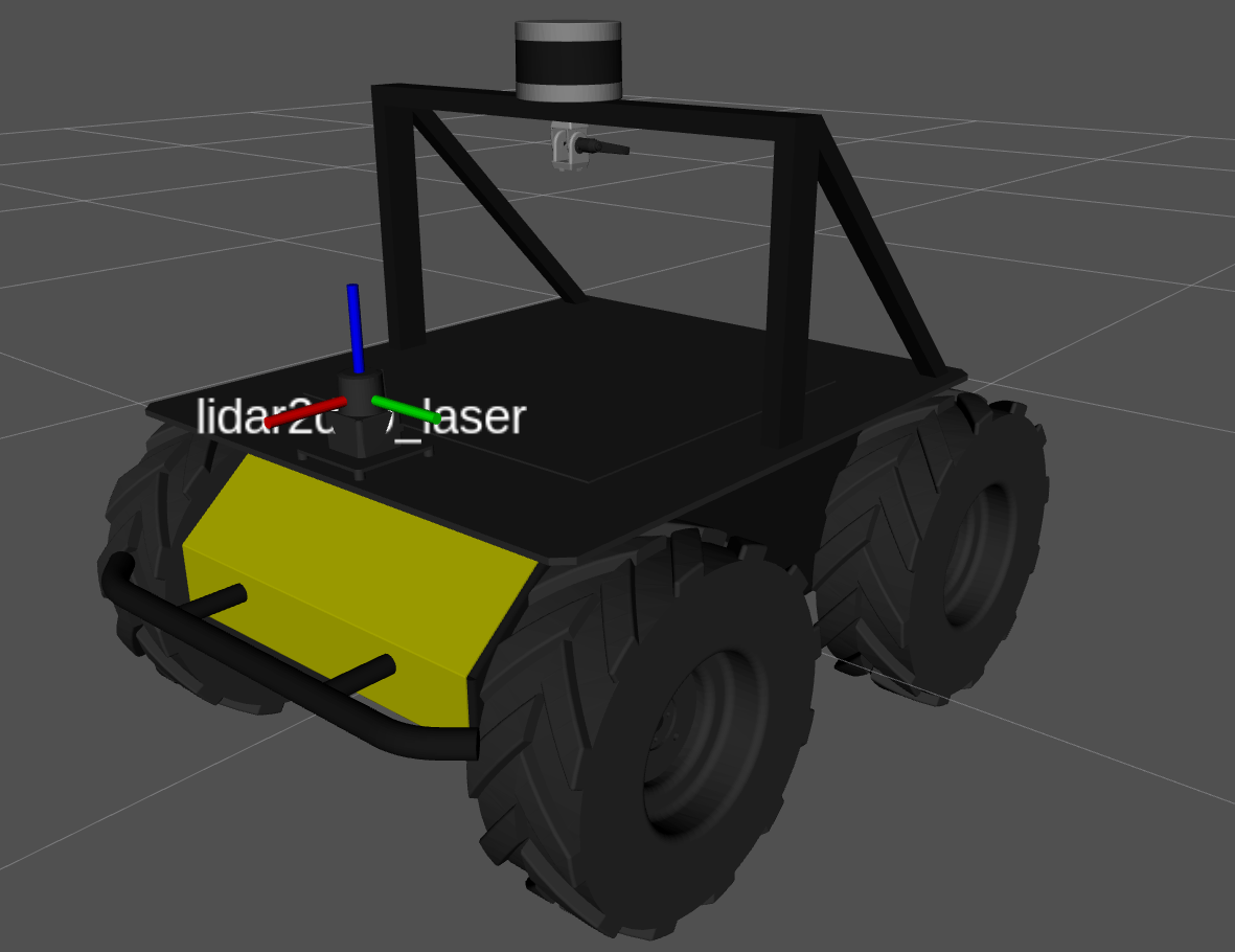
Next, we will add a hokuyo_ust to the bracket we added earlier. Since that is the first bracket, then it's mounting location will be: bracket_0_mount; setting the parent link of the sensor, we get:
lidar2d:
  - model: hokuyo_ust
    urdf_enabled: true
    launch_enabled: true
    parent: bracket_0_mount
    xyz: [0.0, 0.0, 0.0]
    rpy: [0.0, 0.0, 0.0]
    ros_parameters:
      urg_node:
        laser_frame_id: lidar2d_0_laser
        ip_address: 192.168.131.20
        ip_port: 10940
        angle_min: -2.356
        angle_max: 2.356
For the final step, we will add an intel_realsense to the fath_pivot mount that we added. Because it is the first fath_pivot, it's mounting location will be: fath_pivot_0_mount; setting the parent link of the sensor:
camera:
  - model: intel_realsense
    urdf_enabled: true
    launch_enabled: true
    parent: fath_pivot_0_mount
    xyz: [0.0, 0.0, 0.0]
    rpy: [0.0, 0.0, 0.0]
    ros_parameters:
      intel_realsense:
        camera_name: camera_0
        device_type: d435
        serial_no: '0'
        enable_color: true
        rgb_camera.profile: 640,480,30
        enable_depth: true
        depth_module.profile: 640,480,30
        pointcloud.enable: true

Leaving the other sections empty, leaves us with the full sensors section:
sensors:
  camera:
    - model: intel_realsense
      urdf_enabled: true
      launch_enabled: true
      parent: fath_pivot_0_mount
      xyz: [0.0, 0.0, 0.0]
      rpy: [0.0, 0.0, 0.0]
      ros_parameters:
        intel_realsense:
          camera_name: camera_0
          device_type: d435
          serial_no: '0'
          enable_color: true
          rgb_camera.profile: 640,480,30
          enable_depth: true
          depth_module.profile: 640,480,30
          pointcloud.enable: true
  gps: []
  imu: []
  lidar2d:
    - model: hokuyo_ust
      urdf_enabled: true
      launch_enabled: true
      parent: bracket_0_mount
      xyz: [0.0, 0.0, 0.0]
      rpy: [0.0, 0.0, 0.0]
      ros_parameters:
        urg_node:
          laser_frame_id: lidar2d_0_laser
          ip_address: 192.168.131.20
          ip_port: 10940
          angle_min: -2.356
          angle_max: 2.356
  lidar3d:
    - model: velodyne_lidar
      urdf_enabled: true
      launch_enabled: true
      parent: sensor_arch_mount
      xyz: [0.0, 0.0, 0.0]
      rpy: [0.0, 0.0, 0.0]
      ros_parameters:
        velodyne_driver_node:
          frame_id: lidar3d_0_laser
          device_ip: 192.168.131.25
          port: 2368
          model: VLP16
        velodyne_transform_node:
          model: VLP16
          fixed_frame: lidar3d_0_laser
          target_frame: lidar3d_0_laser