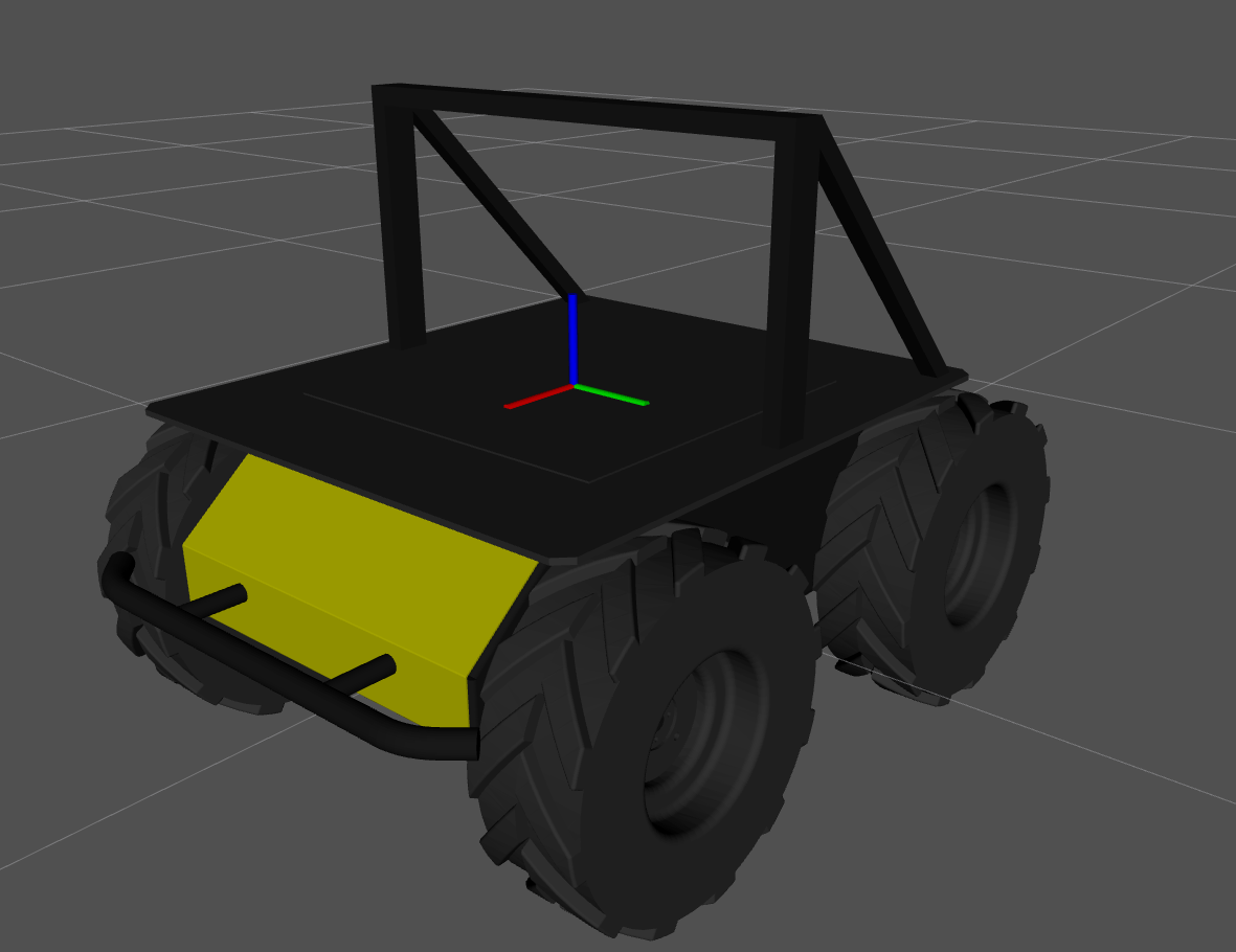
Mounts
Most sensors can use similar mounting structures. Therefore, we want to keep mounts separate from sensors, such that users could attach their own sensors to existing mounts.
Riser
A mounting plate with the defined number of rows and columns of the PACS™ 80 mm X 80 mm grid.
At this time, you will need to use the PACS™ top plate, only available using the a200.top_plate with model: pacs, to add these riser mounts. See the platform section for more information.
Preset Risers
These are the most common riser sizes; therefore, we have accurate models of these plates.
8 X 7 Riser
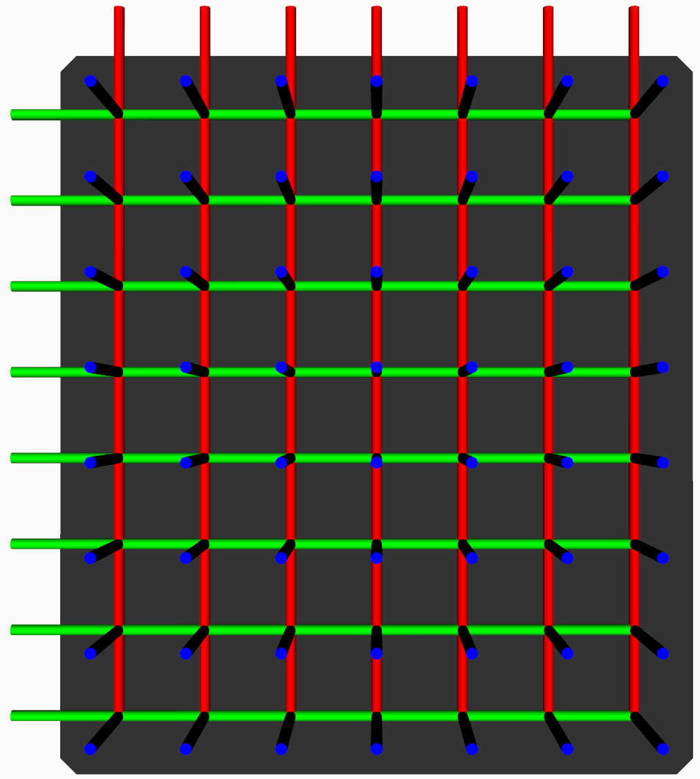 | |
Attach an accessory to the riser by setting the accessory's parent parameter to one of the mounts, riser_0_mount_a1 to riser_0_mount_g8.
It is not recommended to change the parent link of the 8 x 7 riser as it will not align with the top plate.
1 X 7 Riser
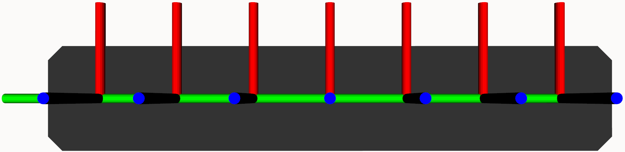 | |
Attach an accessory to the riser by setting the accessory's parent parameter to one of the mounts, riser_0_mount_a1 to riser_0_mount_g1.
The mounting location names are based of the existing grid. If the riser is added to the second row instead by setting the parent parameter to top_plate_mount_a2, then the mounts will be named riser_0_mount_a2 to riser_0_mount_g1.
Custom Risers
To promote flexibility, the size of the risers can be changed to any size; however, there are no models for these, and instead will be generated using primitives.
For example, we can add a riser with a 4 by 4 grid:
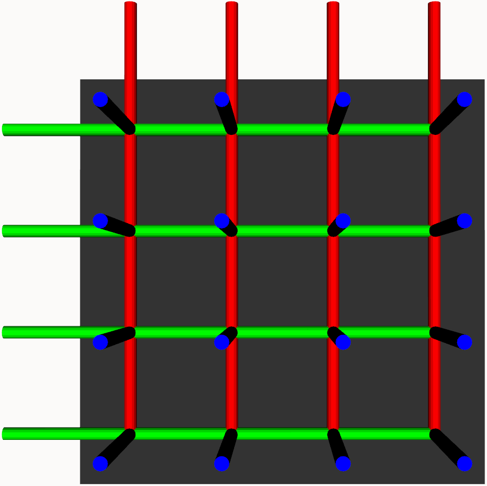 | |
Attach an accessory to the riser by setting the accessory's parent parameter to one of the mounts, riser_0_mount_a1 to riser_0_mount_d4.
The mounting location names are based of the existing grid. If the riser is added to the second row instead by setting the parent parameter to top_plate_mount_a2, then the mounts will be named riser_0_mount_a2 to riser_0_mount_d5.
Bracket
Brackets are small plates with 80 mm X 80 mm screw holes that can be used to attach it to the PACS™ gird. They come in three different models.
The horizontal and vertical models have screw holes to attach all small sensors such as camera, lidars, and IMUs.
The large model has screw holes to attach larger sensors such as the SwiftNav Duro receivers.
Horizontal Bracket
 | |
Attach an accessory to the horizontal bracket by setting the accessory's parent parameter to bracket_0_mount.
Vertical Bracket
 | |
Attach an accessory to the vertical bracket by setting the accessory's parent parameter to bracket_0_mount or bracket_0_vertical_mount.
Large Bracket
 | |
Attach an accessory to the large bracket by setting the accessory's parent parameter to bracket_0_mount.
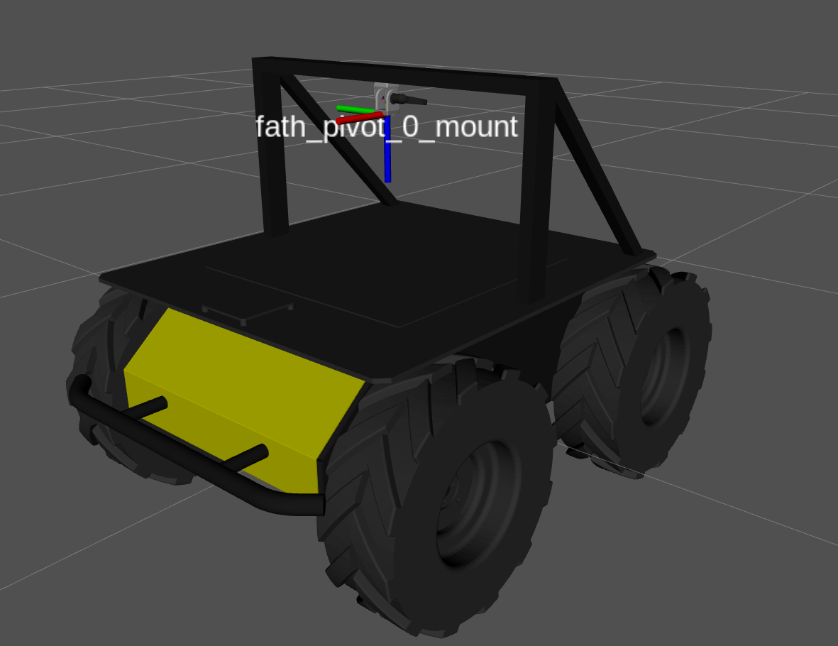
Fath Pivot
Camera mounts with a single joint that can be adjusted to change the pitch of the camera. The angle of the joint is set using the angle parameter.
 | |
Attach an accessory to the fath pivot mount by setting the accessory's parent parameter to fath_pivot_0_mount.
SICK Mounts
These mounts are specifically designed to mount SICK LiDARs, but can be used for other sensors if required.
The orientation of the LiDAR on the mount can be set to either upright or inverted
Upright
 | |
Attach an accessory to the SICK mount by setting the accessory's parent parameter to sick_0_mount.
Inverted
 | |
Attach an accessory to the SICK mount by setting the accessory's parent parameter to sick_0_mount.
Post
Posts are vertical extrusion rails to where sensors can be added.
These can be single, dual, and quad legs.
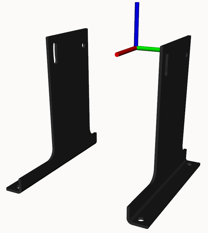
Single
 | |
Attach an accessory to the post by setting the accessory's parent parameter to post_0_mount.
Dual
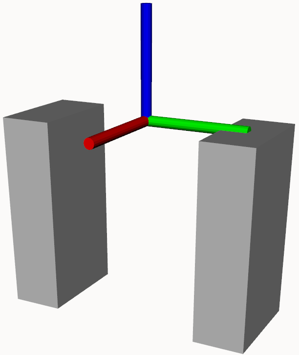 | |
Attach an accessory to the post by setting the accessory's parent parameter to post_0_mount.
Quad
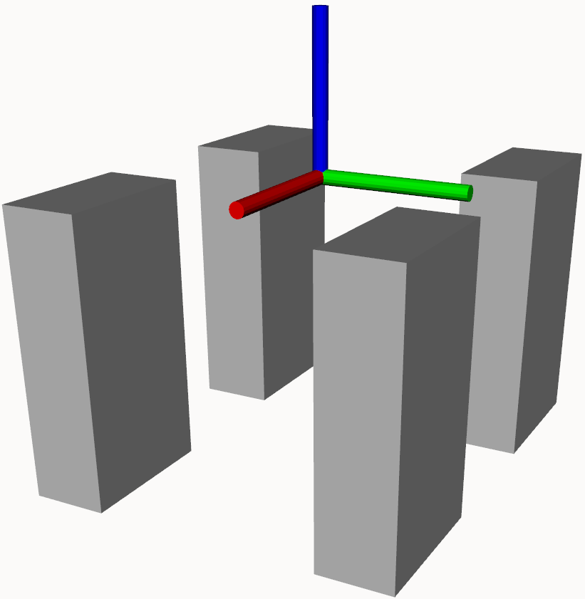 | |
Attach an accessory to the post by setting the accessory's parent parameter to post_0_mount.
Disk
Disk plates are used for circular sensors, such as the Velodyne LiDARs.
 | |
Attach an accessory to the disk post mount by setting the accessory's parent parameter to disk_0_mount.
We can also lift the disk by using a post.
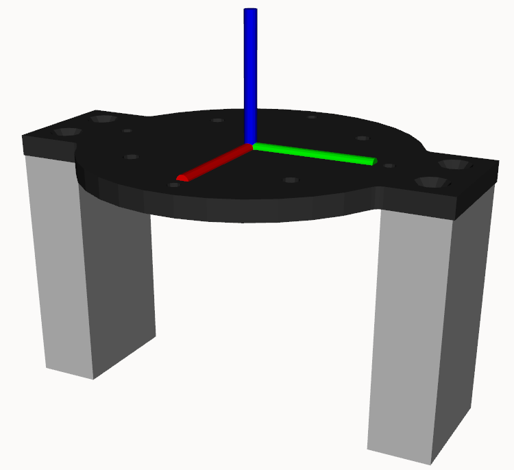 | |
Attach an accessory to the disk post mount by setting the accessory's parent parameter to disk_0_mount.
Sample
Sample A200 Mounts Section
In this sample, we will add a bracket to mount a LiDAR to the front of the Husky A200.
We select the top_plate_mount_d1, in other words, the middle (d), front (1), 80 mm X 80 mm mounting location on the PACS top plate.
bracket:
  - parent: top_plate_mount_d1
    xyz: [0.0, 0.0, 0.0]
    rpy: [0.0, 0.0, 0.0]
    model: horizontal

Then, we want to add a camera to the sensor arch. However, we will complicate things by adding it upside down to the extrusion.
We choose a fath_pivot mount, and then we set its parent to the sensor_arch_mount.
Using the xyz entry, we lower the mount by 21 mm to get it under the sensor arch; then, we roll it by to get it upside down.
fath_pivot:
  - parent: sensor_arch_mount # mount atop the sensor arch
    xyz: [0.0, 0.0, -0.021] # lower pivot mount to below the sensor arch
    rpy: [3.1415, 0.0, 0.0] # roll pivot mount to flip it upside down
    angle: 0.0
Since we did not need a riser, we leave that section empty; the resulting mounts section:
mounts:
  bracket:
    - parent: top_plate_mount_d1
      xyz: [0.0, 0.0, 0.0]
      rpy: [0.0, 0.0, 0.0]
      model: horizontal
  fath_pivot:
    - parent: sensor_arch_mount
      xyz: [0.0, 0.0, -0.021]
      rpy: [3.1415, 0.0, 0.0]
      angle: 0.0
  riser: []
  sick: []
  post: []
  disk: []