Husky A300 Observer User Manual

Click to view this page's table of contents
- Introduction
- System Overview
- Getting Started
- Unboxing the Husky A300
- Turning The Circuit Breaker On
- Turning The Robot On
- Emergency Stop Buttons
- Clearing An Emergency Stop
- Wireless Emergency Stop
- Connecting And Using The Wireless Joystick
- In Case Of A Collision
- Issues With Getting Started
- Connecting To Husky AMP's Network
- Check That Sensors Are Functional
- Confirming That OutdoorNav Software Is Functioning
- Issues With Getting Started
- Operating The Robot
- Maintenance, Preventative
- Maintenance, Base Husky A300
- Common Replacement Items
- Critical Items
- Wiring Diagram
- Tire and Inner Tube
- Motors
- Nameplate And Regulatory
- Electronics Tray
- Battery Integration Tray
- Batteries
- Rear Cover
- Bumpers
- Air Grilles
- Fans
- Power Distribution
- Status Lights
- Network Switch
- Computer
- Replacing CMOS Battery
- Debugging The System Interface Assembly, (Debug LEDs)
- Replacing Circuit Boards
- Replacing Board Mount Fuses
- Replacing Mini Blade Fuses
- Replacing BF1 Fuses
- Lifting, By Hand
- Lifting, With Sling
- Maintenance, Husky AMP
- Custom Integrations
- STEP Model
- base_link
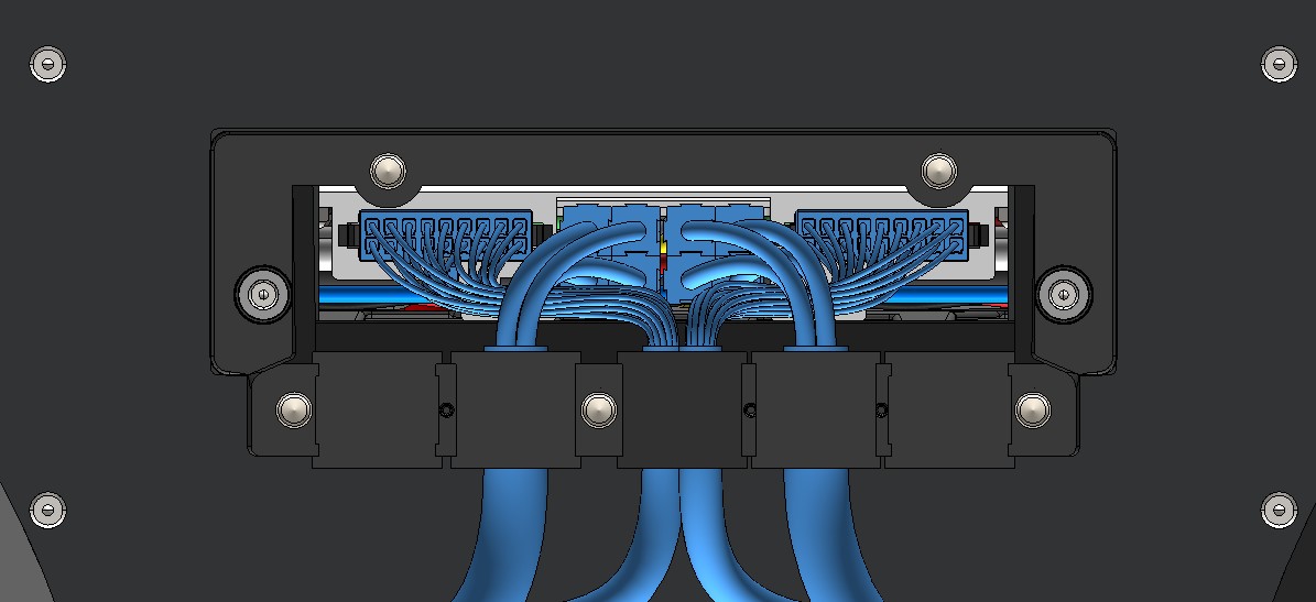
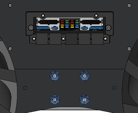
- Internal Integrations
- Data Connections
- System Interface Connector Summary
- Power Connections
- AUX Inputs
- AUX Outputs
- General Purpose Inputs and Outputs (GPIO)
- Fan Expansion
- CANbus Connection
- Additional Emergency Stop Devices
- System Power
- AMP's Interface Control Drawing (ICD)
- AMP's Eurorack Interface, For Custom Electronics
- AMP's Aluminum Extrusions
- Large Component Mounts, Like Arms / Manipulators
- Custom Robot Panel Colour
- Support
Introduction
About
The Husky Observer uses a Husky A300 AMP as its base. The AMP includes the Husky A300 base robot, sensors, autonomy navigation software, and a web user interface for commanding the robot. Husky Observer then adds Autonomous Wireless Charging, and a Pan Tilt Zoom Camera. This manual will explain how to use your Husky Observer, how to add new hardware and software, and how to maintain the robot.
Other Documentation To Review
Refer to our OutdoorNav software's documentation, as this comes included with Husky AMP and Husky Observer. OutdoorNav allows you to send your Husky on autonomous missions using the included ROS API, or by using OutdoorNav's web user interface. OutdoorNav can accomplish these autonomous missions using the Husky AMP's sensors, without making infrastructure updates to your worksite.
Safety
Clearpath Robotics's top priority is the safety of people interacting with our products. Clearpath Robotics produces high power and fast-moving pieces of machinery that could cause serious injury—including death—if the machinery is used or maintained improperly. This documentation includes safety messages corresponding to either a DANGER, WARNING, or CAUTION level to inform your commissioning team of risks related to Clearpath products.
These messages are to assist your commissioning team as they create a Risk Assessment for your application. The Husky A300 may present risks to users even during normal operation. Your commissioning team's Risk Assessment process may add additional design features or safeguards to reduce risks. All operators of the machine should familiarize themselves with the Risk Assessment and this user manual, to be informed of hazards, and to reduce the risk of harm.
DANGER
DANGER indicates a hazardous situation which, if not avoided, will result in death or serious injury.
WARNING
WARNING indicates a hazardous situation which, if not avoided, could result in death or serious injury.
CAUTION
CAUTION indicates a hazardous situation which, if not avoided, could result in minor or moderate injury.
The information found within this documentation is subject to change without notice. This document may be periodically reviewed and revised in the future. Clearpath Robotics assumes no responsibility for any errors or omissions that may appear in this document. In no event shall Clearpath Robotics be liable for any costs or damages arising from the use of this document or the hardware and software described within. The reference documents listed in this manual shall be applicable at the latest revision in effect.
While Clearpath Robotics does its best to inform its users of potential risks, it is impossible to provide an exhaustive list of all possible hazards in your environment.
It is the responsibility of the user to be familiar with all applicable safety standards and ensure that the hardware, software, and/or services delivered by Clearpath Robotics (collectively referred to as the "Product") are maintained and operated in a safe manner, in a suitable environment, and in accordance with the recommended maintenance requirements prescribed by Clearpath Robotics.
Without limiting the foregoing, it is the user's responsibility to ensure that personnel operating the Product are adequately trained and comply with all laws, regulations, codes, and safe practices, including health and safety and workers's compensation laws, applicable to the user's activities and its ownership, possession, and use of the Product. Modification, removal or addition of components, or changes to the functionality or operation of the Product in any way, except as expressly authorized by Clearpath Robotics, may jeopardize the safety of the Product.
If at any time you have any questions or concerns regarding the safe operation of your Clearpath Robotics product, contact Support.
These are the hazards Clearpath Robotics is aware of for the Husky A300. Your commissioning team may find more hazards due to the Husky operating in your unique application.
Click To Expand, To Show All The Hazards
DANGER
Do not operate the robot near vulnerable people such as infants and children.
DANGER
Husky A300 does not include any safeguards to prevent it from driving over a cliff.
Husky is at least 80 kg, and likely to cause serious injury or death when landing on a person.
Your commisioning team must consider this hazard and add add design features and safeguards to reduce this risk—such as by constraining the Husky within a worksite without cliffs.
DANGER
Do not operate Husky A300 near ladders. The robot could hit ladders, and cause these to become unstable, resulting in a person falling from a height.
DANGER
The Husky A300 may operate near racking. Racking must be securely fastened, and be loaded to prevent falling items.
It is the commissioning and operating teams's responsibility to ensure that the Husky A300 colliding with racking will not cause items to fall on a person. It is the commissioning team's responsibility to ensure local regulations are followed.
DANGER
Do not operate Husky A300 in explosive atmospheres. Do not use the Husky near flammable liquids, gases, or dust. Husky A300 can create sparks which may ignite the dust or fumes.
DANGER
Custom attachments such as towed trailers and manipulators were not been considered in Clearpath Robotics's risk assessment process. These custom attachments can crush or strike people, causing severe injuries or death.
Your commisioning team must consider this hazard and add add design features and safeguards to reduce this risk—such as adding physical guards, or PLC interlocks with the Emergency Stop system.
WARNING
Husky A300 with payload can have a total kinetic energy of 360 joules of energy (180 kg at 2 m/s). This is a significant amount of energy that can cause severe injury or death.
Husky A300, Husky AMP, and Husky Observer have been designed to ensure the robot will not impact a person's torso or head.
Your commissioning team must ensure custom payloads to not create impact points near a person's torso or head.
Your commissioning team must review the worksite procedures, to reduce the risk of the robot colliding with a person.
WARNING
Do not ride on a moving Husky A300. This includes standing, sitting, or any other method of moving a person using a Husky A300.
The robot may become unstable or move unpredictably.
WARNING
The Husky A300 may cause issues with pacemakers or other medical devices due to EMI or EMC.
Refer to Husky's test report—clearpath_robotics_032721-RPT1_3.pdf—per IEC 61326-1.
WARNING
Always use chock blocks on the wheels when powering off the robot. Husky A300 can roll on slopes when the robot is unpowered.
WARNING
Always power off Husky A300 and set the Battery Circuit Breaker to the Off position before performing maintenance. Electrical shock or fire may occur when accessing the interior of the Husky A300, or from live voltage cables on the outside of the robot.
WARNING
Ensure that you follow all guidance for Husky A300 regarding allowable slopes, allowable payload mass, and allowable payload location. Husky A300 can tip over if subjected to slopes or vertical drops outside the allowable range. Husky A300 can tip over while driving on acceptable terrain if payloads are not within the robot's allowable centre-of-gravity stability cone.
WARNING
Only operate Husky on the intended operating terrain, within the allowable payload and velocity limits. Low friction surfaces like ice can cause erratic or unstable motion of the robot.
WARNING
Keep hands, feet, and other objects clear of the Husky A300 while driving. Objects can be pinched between the Husky A300 and other fixtures in the environment, or between the Husky A300's wheels and the Husky A300's frame or payloads.
Design your custom payloads so they prevent pinching, crushing, and entanglement.
CAUTION
Always follow the safe lifting procedure for Husky A300 as detailed in this manual. The robot may be lifted by 2 people at the 2 bumpers, or with lifting slings under the robot.
Do not lift the Husky A300 with a fork truck's forks under the robot's chassis.
Only lift the robot to table height.
CAUTION
Follow safe fork truck lifting procedures when lifting the Husky A300's crate. The crate includes wood blocks to retain the crate on the forks.
CAUTION
Husky can become unstable or fall if driven over ledges greater than 150 mm. Husky can become unstable if driven at high speed over ledges between 20 mm - 150 mm.
CAUTION
The Husky's external and internal edges have been rounded to reduce the risk of cuts. Edges may become burred due to damage through use. Attempt to grasp parts during maintenance, without sliding hands along edges. This reduces the risk of pinches or cuts.
CAUTION
Do not use the provided Standard Charger outside. Dry the robot before using the battery's Standard Charger.
The Standard Charger includes a power cable and regulatory marks for the destination country of the your purchase order. Confirm these are acceptable for your worksite before use.
CAUTION
Dry the Husky A300's Rear Charge Port Door before opening it. Do not open the during heavy rain—(more than 1 mm per hour)—or when wind is angling the rainfall.
The robot's manual charge connector is visible behind the Rear Charge Port Door. This connector has live battery voltage when the circuit breaker is in the On position.
The voltage at this connector is less than 30 VDC, so it should not cause shocks in damp conditions.
CAUTION
Husky A300 can present a tripping hazard.
Husky A300 can be anywhere in the operating area at any time and may pose a tripping hazard even when not in motion.
Ensure the Husky A300 is parked in a location away from walkways when the robot is not operating.
CAUTION
This manual includes Interface Control Drawings and STEP models for helping you design custom payloads for Husky A300. Follow the payload allowances, stability limits, and suggested operating conditions to maintain stability of the robot and payload. Payloads should be securely fastened to Husky to maintain stability, and prevent objects being thrown from the robot.
CAUTION
The Husky A300 may collide with carts or other objects on casters. This may cause carts to move or become unstable.
Operating teams should park carts outside the Husky A300's operating area.
CAUTION
The Husky A300 has a battery that does not exceed 30 VDC. It is unlikely to shock you due to this low voltage.
Shut off the circuit breaker, and dry the robot before performing maintence.
Husky AMP and Husky Observer include PoE devices. PoE can provide up to 60 VDC.
These devices include waterproof cables, to reduce the risk of shock.
CAUTION
The Husky A300 may build up a static charge as it does not have a static dissipation strap. This static charge may shock you when you touch the robot.
Refer to Husky's test report—clearpath_robotics_032721-RPT1_3.pdf—per IEC 61326-1.
CAUTION
A standard Husky A300 does not include lidar or other devices with Class 1 lasers per IEC 60825-1.
The Husky AMP and Husky Observer include lidar with a Class 1 notice. Class 1 lasers are safe in normal use, without causing damage to eyes or skin.
Review your local regulations for workplace requirements with Class 1 lasers.
CAUTION
Pushing or pulling an unpowered Husky can cause back strain, and increases the risk of slips and falls.
Consider your posture when moving an unpowered robot. Consider updating your worksite procedures to reduce how often unpowered robots need to be moved. Only move the Husky while you are wearing high traction footwear, on dry surfaces. Make sure the Husky is powered off before pushing or pulling the robot.
Follow your worksite's guidelines for cleaning flooring.
CAUTION
Ensure that there are no objects in the operating environment that will could move due to an impact with a free-rolling robot. The Husky A300 can roll when it is in an Emergency Stop state. The Emergency Stop state removes power from the drive motors, but does not engage a friction brake. Consider how your operating environment's slopes, the payload mass on the robot, and the velocity of the robot affect this risk.
CAUTION
Always tie up long hair, and remove loose jewellery, and wear clothing without snag points when working around Husky A300. This reduces the risk of entanglement with the moving robot.
CAUTION
Follow the proper Lockout procedure for Husky A300 when completing inspections or maintenance. A related Tagout procedure should be developed and followed at your worksite.
Access to live voltage inside Husky A300 may occur if the Lockout procedure is not followed, which may result in electric shock or a fire. Lockout prevents unintended motion of the machinery, since the motors will not receive power. Lockout prevents cuts and crushing from moving fans and motors.
CAUTION
Always wear gloves, preferably nitrile gloves, while performing maintenance on the robot. Internal maintenance on Husky A300 may expose the technician to harmful chemicals in dust, fluids, thermal paste, thread locking adhesives, electric grease, batteries, and material coatings.
CAUTION
Always place Husky A300 at a suitable height when working in or around Husky A300. Bend at the knees when working on the robot at ground level to avoid fatigue and injury.
CAUTION
The robot may become unstable as you remove items for maintenance. Place the entire bottom surface of the Husky's chassis on a table when removing wheels to maintain the robot's stability.
CAUTION
The Husky A300 should not cause health issues due to high power radio waves. Review Husky's test report—clearpath_robotics_032188-COC1_3.pdf—to confirm that the results per FCC part 15 subpart B / ICES-003 are acceptable for your worksite.
Intended Use
Husky A300 is intended for use in:
- Indoor and outdoor research laboratories and light industrial environments for inspection, materials transport, and manipulation.
- Environments free of vertical drops greater than 150 mm.
- Environments free of fast moving people or vehicles.
- Environments free of infants and children.
- Environments free of glass or transparent plastic floors or walls.
- Environment temperatures between -20°C and +40°C.
- Environments free of open water or other liquids deeper than 130 mm.
- Environments free of grades greater than 15°.
- Environments with pollution degree 1, 2, or 3 (per IEC 61010-1).
- Environments at altitudes less than 2000 m.
The system is intended to be operated by trained personnel familiar with mobile robotic technology. It is intended to be monitored constantly by those personnel during operation.
The system is intended to be operated around trained personnel familiar with the hazards that the system presents.
The system is intended to be operated in the as-furnished condition, without additional equipment, payload or passengers.
What's Included?
- Husky A300 base robot
- Husky AMP's enclosure and sensors installed on top of the Husky A300 base robot.
- Husky Observer's autonomous wireless charger and stationary dock.
- Husky Observer's pan-tilt-zoom camera.
- Wireless joystick
- Battery charger
- Spare parts
- Crate, with straps to retain the robot
Clearpath Robotics also provides integration services. Your order may include additional sensors, auxiliary hardware, or software packages. This additional work will come preinstalled on your robot.
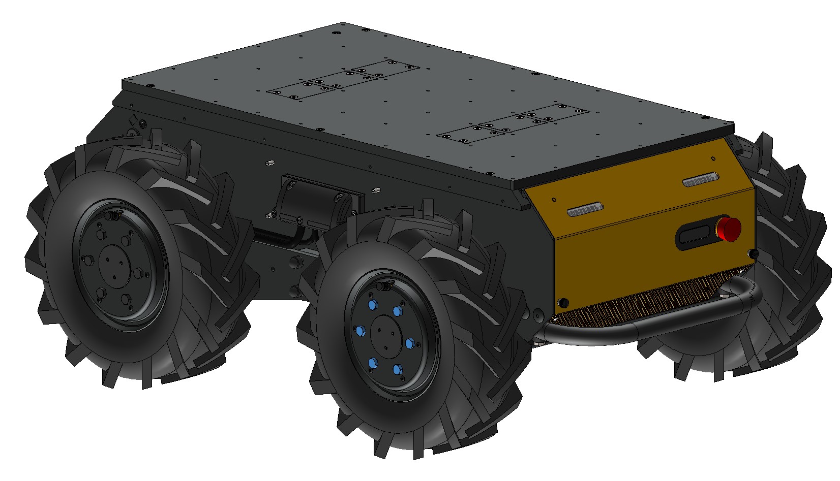
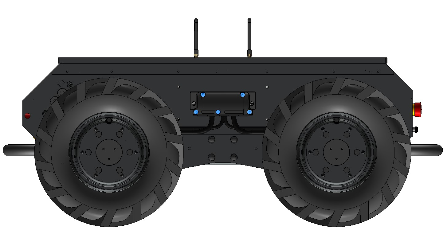
System Overview
Components
- Chassis
- Mobility, including wheels and gearmotors
- User payload area, including cable passthrough ports
- Bumpers
- Status display
- Status lights
- Power button
- Emergency Stop restart button
- Rear Charge Port Area, (Battery's circuit breaker, battery's manual charge port, HDMI / USB / Ethernet debug ports, wireless Emergency Stop bypass keyswitch)
- Air grilles
- Wi-Fi antennas
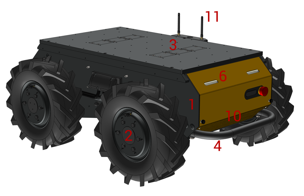
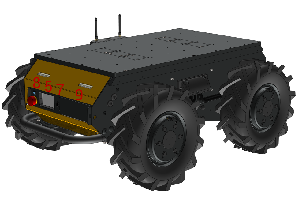
Additional Components Related To Husky AMP
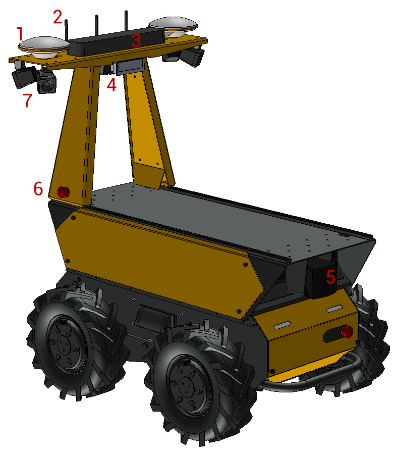
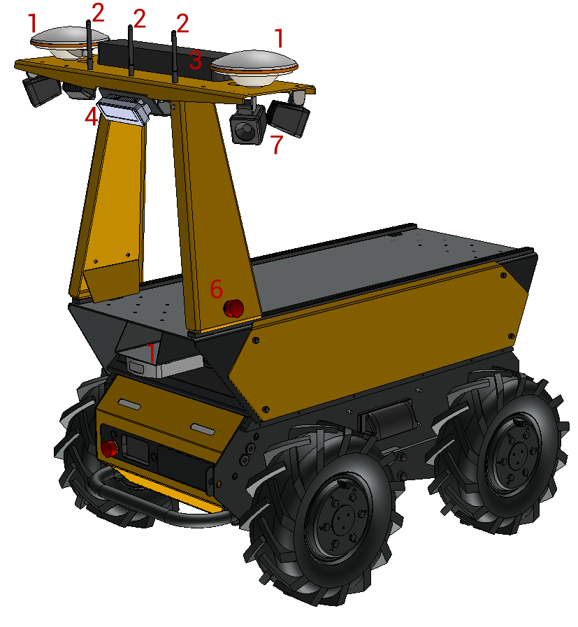
- GNSS antennas and Positioning Unit, (Fixposition Vision RTK 2)
- Wi-Fi and Bluetooth antennas, (relocated)
- Cellular antennas, all-in-one unit
- Teleoperation cameras, (Luxonis Oak-D Pro W PoE)
- Directional 3D lidar, (Seyond Robin W)
- Additional Emergency Stop Buttons
- Lights
- Sounder, (hidden behind panels)
Additional Components Related To Husky Observer
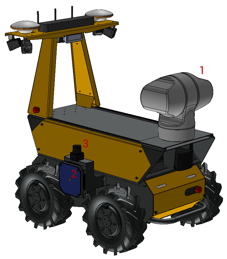
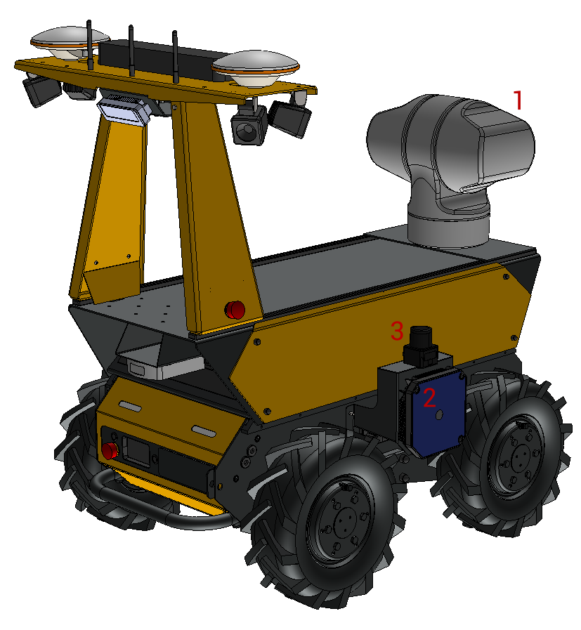
- Pan-Tilt-Zoom Camera, (Axis Q6225-LE)
- Wireless Charge Coil, (Wiferion)
- 2D lidar, (Hokuyo UST10-LX)
Technical Specifications
| Husky A300, 40 Ah | Husky A300, 80 Ah | Husky A300, 120 Ah | |
| Battery, Chemistry | |||
| Battery, Nominal Voltage | |||
| Battery, Capacity | |||
| Battery, Capacity | |||
| Operating Time, Average6 | |||
| Operating Time, Standby | |||
| Charge Time, Standard Charger (North America) | |||
| Charge Time, Standard Charger (Europe) | |||
| Charge Time, Upgraded 650 W Charger | |||
| Charge Time, Upgraded 1200 W Charger | |||
| Charge Time, Wireless Charger | |||
| Mass, Robot | |||
| Centre Of Mass, Robot, X7 | |||
| Centre Of Mass, Robot, Y7 | |||
| Centre Of Mass, Robot, Z7 | |||
| Mass, Allowable Payload1 | |||
| Mass, Allowable Payload For All Terrain2 | |||
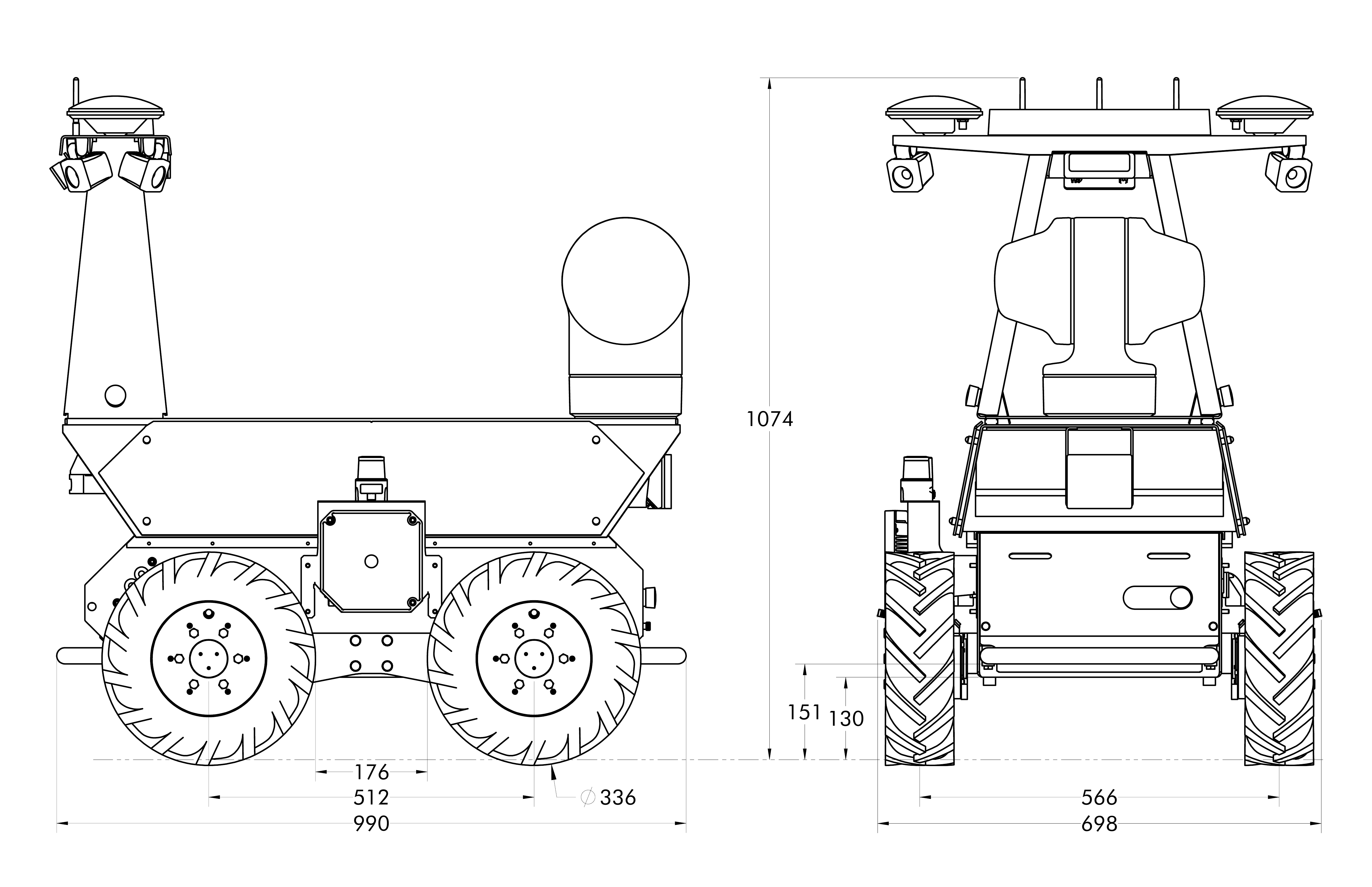
| Dimensions, Length | |||
| Dimensions, Width | |||
| Dimensions, Height | |||
| Dimensions, Wheelbase Length | |||
| Dimensions, Track Width | |||
| Dimensions, Ground Clearance | |||
| Dimensions, Nominal Tire Diameter | |||
| Dimensions, Effective Tire Radius | (value for odometry control software) | ||
| Mobility, Total Power | |||
| Mobility, Maximum Speed3 | |||
| Mobility, Maximum Climb Grade4 | |||
| Mobility, Allowable Sideslope | |||
| Environment, Storage Temperature | |||
| Environment, Operating Temperature5 | |||
| Environment, Charging Temperature | |||
| Environment, Operating Humidity | |||
| Environment, Ingress Protection | |||
| User Power, 12 V | |||
| User Power, 24 V | |||
| User Power, VBAT | |||
| User Power, Large VBAT | |||
| Computer Options | Performance: i7-13700TE Processor GPU Optional | ||
1 Continuous operation on relatively flat terrain with wide turns. See also Important System Limits
2 Robot climbing 30° grade with high-mounted payload, or turning in place in high-friction conditions such as asphalt, concrete, and carpet. See also Important System Limits
3 Maximum speed should be limited to 1 m/s in off-road conditions when the payload exceeds 50 kg. See also Important System Limits
4 See also Important System Limits for additional considerations related to slopes.
5 Robot must be powered on at a minimum temperature of 0 °C.
You may notice odd sensor data as the AMP or Observer warms up; such as with the included Luxonis OAK-D Pro cameras which limits its functionality when internal components are cold.
6 Based on 33% driving at 2 m/s with 50 kg payload on level ground and 67% idle.
7 With reference to the Husky A300's base_link.
System Architecture
Click to see the detailed explanation:
Husky is built around a computer running Ubuntu—(Intel-based computer)—paired with a 32-bit microcontroller unit, (MCU).
The MCU handles low level hardware functions such as power supply control, light control, fan control, display control, and hardware monitoring. The computer and MCU communicate with Ethernet.
The motor controllers and batteries connect to the MCU through individual CANbuses. The MCU's firmware then passes this to the computer over Ethernet. The computer is configured with SocketCAN to interface with these networks.
The computer then connects to other devices through Ethernet and USB. Most Huskies include an IMU connected to the primary computer with USB. Husky AMP connects lidar and camera through these interfaces.
IP Addresses
| IP Address | Device |
| 192.168.131.1 | Computer, Primary |
| 192.168.131.2 | Common Core MCU |
| 192.168.131.5 | Computer, Secondary, (Optional) |
| 192.168.131.10 | Axis Q62 Pan-Tilt-Zoom Camera |
| 192.168.131.15 | Front OAK-D Camera |
| 192.168.131.16 | Rear OAK-D Camera |
| 192.168.131.20 | Side Hokuyo Lidar |
| 192.168.131.25 | Seyond Robin W Lidar |
| 192.168.131.35 | Fixposition Vision RTK 2 Positioning |
| 192.168.131.51 | Peplink Access Point |
Our Network IP Addresses page lists the common ranges we use per sensor type. Clearpath will provide a supplementary manual that includes the IP addresses of custom configuration sensors.
Safety System Functionality
Husky A300 is equipped with 3 safety functions to reduce the system risk:
- The robot includes Emergency Stop buttons. When any button is pressed, it triggers an emergency stop, (PLc per ISO 13849).
- When the Rear Charge Port Door is opened, it triggers an emergency stop, (PLc per ISO 13849). This prevents the robot from moving while connected to the battery charger.
- The robot is equipped with an electrical braking system that reduces the speed of the robot when the Emergency Stop is engaged, (PLa per ISO 13849).
Your commissioning team must evaluate the functionality of Husky's safety functions in the context of your worksite and use case. Perform a Risk Assessment to understand the risks of deploying Husky in your application, and whether customizations should be made to reduce these risks.
ISO 12100 is the Risk Assessment guide that we use at Clearpath Robotics, but there are other options from standards agencies like ISO, and IEC.
We recommended that Husky's safety functions are tested after shipping, and before each use. Refer to the Pre-Operation Inspection section for details.
Getting Started
Unboxing the Husky A300
To remove the Husky A300 from its crate:
- Remove the bolts securing the front panel of the crate.
You will need a 14 mm hex socket for this.
- Position the front panel as a ramp at the bottom of the crate.
- Loosen and remove the retaining straps.
- Roll the Husky A300 out of the crate.
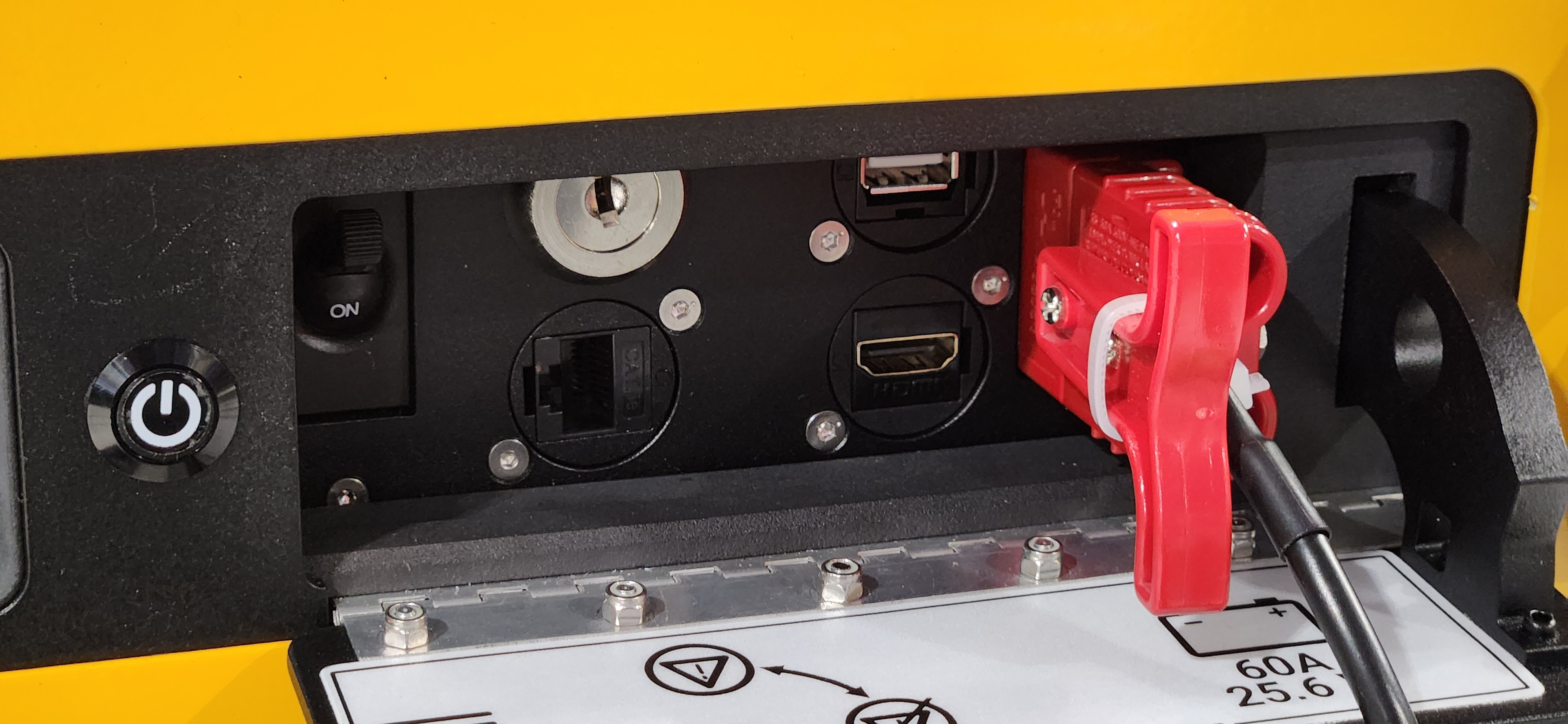
Turning The Circuit Breaker On
The Husky's Circuit Breaker disconnects the robot's batteries from all of the robot's electronics, including battery chargers. We ship the Husky with the circuit breaker in the OFF position. This breaker may also flip to the OFF position if your robot draws more than 100 A of current, or if its batteries are almost depleted.
To turn the breaker to the ON position:
- Open the Husky's Rear Charge Port Door.
- Flip the Circuit Breaker to the ON position.
- Close the Rear Charge Port Door.
Turning The Robot On
To turn the Husky on:
- Check that the Circuit Breaker is in the ON position.
- Press and hold the Power Button for 0.5 seconds.
Press and hold the Power Button for 0.5 seconds to turn the Husky off. Holding the button for longer will not force the robot to shut down faster.
Emergency Stop Buttons

WARNING
Ensure the 2 Emergency Stop buttons are accessible at all times. Do not mount custom payloads that extend over the front or rear of Husky, that occlude the Emergency Stop buttons.
The Emergency Stop buttons remove battery power from Husky's motors. Power is removed through 2 normally-open relay-contactors. Both relay-contactors open when an Emergency Stop button is pressed. The 2 relays are connected in series, so if one welds closed due to a failure, there is a backup relay to disconnect the motors. The relays's physical states are monitored with Husky's Common Core microcontroller, and should flag a maintenance issue if either relay is damaged.
Husky's microcontroller does not meet any performance level per ISO 13849-1. Husky's microcontroller can be replaced with a PLC to achieve a known performance level for fault monitoring. Contact our Support Team if you have questions about this.
When in the Emergency Stop state, the status lights will flash red, and Husky will not drive. The commands received during Emergency Stop mode are not buffered; Husky will always act on the latest commands received. This means that if the commands are stopped before the stop is released, the Husky will not move. If the commands are continued, Husky will move at the speed commanded once the stop is released and motion is re-enabled.
This Emergency Stop function can be asserted by pressing any of the Husky's red stop buttons.
This Emergency Stop system is intended for use in emergency situations only. The Emergency Stop system should not be used as the means of controlling robot motion during regular operation. Frequent use increases the probability of damaging a component of the Husky's safety system.
Clearing An Emergency Stop
The Husky's status lights show these light patterns for different Emergency Stop states:
| Lighting State | Lighting Pattern |
|---|---|
| Emergency Stop |  |
| Needs Reset (after Emergency Stop) |  |
| Operational (Driving or Idle) |  |
The Emergency Stop State Happens When:
- Any of the Husky's Emergency Stop Buttons are depressed.
- The Husky's Rear Charge Port Door is open. This door has a limit switch, which is connected to the robot's Emergency Stop loop.
- The optional Wireless Emergency Stop's button is depressed.
- The Wireless Emergency Stop Keyswitch is set to enabled, even though you do not intend to use the optional Wireless Emergency Stop Transmitter.
- And custom integration's Emergency Stop devices are exerting a stop. This is not included with a standard Husky A300, AMP, or Observer, but may be included if you have custom devices added to your robot like a safety lidar, manipulator, or PLC.
To Clear The Emergency Stop State:
- Twist all the Emergency Stop Buttons.
- Close the Husky's Rear Charge Port Door.
- If included; connect the Wireless Emergency Stop to the Husky.
- If included; clear the Emergency Stop State on your custom devices.
After clearing the Emergency Stop, the Husky's status lights should change to the Needs Reset state's pattern. This state is common for machinery safety; as it waits for the machine operator to confirm that the machine should continue normal operations.
To Clear The Needs Reset State:
- Press the Emergency Stop Restart Button on at the back of the Husky.
- Alternatively, it can be clearing by running
ros2 service call /a300_00000/platform/mcu/clear_estop_needs_reset std_srvs/srv/Empty "{}"on the Husky's computer. - Or, if included, connect your Wireless Emergency Stop remote.
Wireless Emergency Stop
This is an optional add-on kit.
This kit adds some electronics inside the Husky, adds another antenna to the Husky, and includes a handheld transmitter for exerting an Emergency Stop.
To use the Wireless Emergency Stop:
- Turn off the Husky.
- Open the Rear Charge Port Door at the back of the Husky.
- Turn the Wireless Emergency Stop Bypass Keyswitch to the enable position (vertical).
- Turn on the Husky.
- With the Wireless Emergency Stop Transmitter:
- Stand within 40 metres of the Husky.
- Twist the transmitter's red button (GSS).
- Insert the Transmitter's key (M-KEY).
- Hold the Start button. The green LED should start blinking quickly. This indicates that the transmitter has connected to the robot, but is still in a Emergency Stop state.
- Press the Start button again. The green LED should start blinking slowly. This indicates that the Emergency Stop state has been cleared.
The Husky's Status Lights should now be in an operational state.
| Lighting State | Lighting Pattern |
|---|---|
| Emergency Stop | |
| Needs Reset (after Emergency Stop) | |
| Operational (Driving or Idle) | |
- Press the red button (GSS) to exert an Emergency Stop.
- Store the Wireless Emergency Stop Transmitter with the red button depressed. This is also the transmitter's off button.
- The transmitter will automatically exert an Emergency Stop if it loses signal to the robot. Keep the transmitter within 40 metres of the robot to maintain the connection.
- The transmitter will automatically exert an Emergency Stop if it is low battery.
The Wireless Emergency Stop is intended for use in emergency situations. It should not be used as the means of controlling robot motion during regular operation.
Your worksite commissioning team should have created a Risk Assessment for using Husky in their application. The Wireless Emergency Stop Bypass Keyswitch should not be set to disabled if your Risk Assessment required the use of this optional kit.
Connecting And Using The Wireless Joystick
Your robot included a PS4 wireless joystick. Clearpath's robot builders paired this wireless joystick with your robot computer's Bluetooth. This means the joystick should always connect to that robot, even if there are other robots nearby.
To connect the joystick to your robot:
- Turn on the robot, and wait till the status lights show that ROS is running.
- Have the controller within 5 metres of the robot.
- Press the PS button in the centre of the joystick.
- The joystick's top LED should start pulsing white or blue. This means the joystick is attempting to connect.
- The joystick's top LED should eventually become solid blue, indicating that it has connected to the robot's computer.

The Wireless Joystick is not connected if its LED does not become solid blue. Follow the instructions in the Joystick Controller Pairing section to pair the joystick to your robot's primary computer.
- Make sure your worksite is ready to drive the robot, and that the robot will not create hazards for people, animals, or your infrastructure.
- Make sure the robot's status lights show that it is ready to drive.
- Make sure the Wireless Joystick is connected to the robot.
- Hold the joystick's L1 button for slow driving. (You can use the R1 button for fast driving once you are comfortable with the robot's dynamics.)
- Use the left joystick to drive the robot. Pushing the joystick forward and backward will command the robot ±X. Angling the joystick left and right will command the robot to rotate ±Z.
In Case Of A Collision
Your commissioning and operations teams should develop procedures for how to deal with incidents, like a robot hitting a person.
- Stop the robot by pressing a red Emergency Stop button on the robot or an equipped attachment.
- Is anyone hurt? Administer first aid immediately. Seek medical attention if necessary.
- Document the incident.
- Follow workplace injury and accident reporting procedures.
- Note the time and place.
- Note which robot was involved.
- Interview any witnesses.
- Take photos or make a drawing.
- Assess the state of the robot.
- Visually inspect the robot for damage and take photos of any damage found.
- If there is no visible damage, observe the robot after it returns to service.
- If any irregularities or differences in its behavior are observed, remove the affected robot from service.
Issues With Getting Started
Please contact our support team if you had any issues with these Getting Started steps. Husky goes through a quality assurance inspection at our facility before we package it, but some items can be damaged during shipping.
Connecting To Husky AMP's Network
To access additional Husky AMP functionality, a network connection to the robot is required. The easiest way to accomplish this is to connect your laptop to Husky AMP's Wi-Fi access point using the steps below.
-
Use your laptop to find and to connect to Husky AMP's Wi-Fi network. The Wi-Fi network name (SSID) will be
cpr_a300_amp_XXXXX, whereXXXXXmatches the serial number of the Husky AMP. When prompted, use the passwordclearpath. -
Confirm that your laptop's Wi-Fi network interface is configured to use DHCP and that it has been assigned an IP address in the
192.168.131.XXXrange.
Refer to Robot Network Connection for alternative networking connections.
Check That Sensors Are Functional
Husky AMP includes several sensors that are used for robot navigation. After connecting to Husky AMP's network, confirm that each sensor is functional by using the steps below.
- Connect your laptop to the robot using SSH. To do so, execute the following in a terminal window:
You will be prompted to enter a password. The default password is
ssh robot@192.168.131.1clearpath. - Use the
pingcommand to check that each of the sensors is functional. For example, to confirm that the front teleop camera (192.168.131.15) is working:$ ping 192.168.131.15
PING 192.168.131.15 (192.168.131.2) 56(84) bytes of data.
64 bytes from 192.168.131.15: icmp_seq=1 ttl=255 time=0.265 ms
64 bytes from 192.168.131.15: icmp_seq=2 ttl=255 time=0.213 ms
64 bytes from 192.168.131.15: icmp_seq=3 ttl=255 time=0.282 ms
64 bytes from 192.168.131.15: icmp_seq=4 ttl=255 time=0.216 ms
^C
--- 192.168.131.15 ping statistics ---
4 packets transmitted, 4 received, 0% packet loss, time 3100ms
rtt min/avg/max/mdev = 0.213/0.244/0.282/0.030 ms
Confirming That OutdoorNav Software Is Functioning
Husky AMP includes OutdoorNav Software, which allows the robot to be operated autonomously. Follow the steps below to confirm that OutdoorNav Software is functioning.
- Connect to Network and Web UI access
- Connect to an RTK Source
- Check camera views
- Complete system configuration:
- Load map tiles
- Set dock location, if a dock is included with your system
- Create your first map
- Create your first mission
- Execute your first mission
Issues With Getting Started
Please contact our support team if you had any issues with these Getting Started steps. Husky goes through a quality assurance inspection at our facility before we package it, but some items can be damaged during shipping.
Operating The Robot
Pre-Operation Inspection
Performing a circle check can reduce safety risks, increase the operating lifespan of the robot, and improve the efficiency of your work. These are our suggested daily checks before sending the Husky on missions:
- Check that the weather forecast has acceptable conditions for the robot.
- Check that the intended worksite's terrain is acceptable, without deep trenches, overhanging obstacles, children, or other hazards that were not acceptable per your Risk Assessment.
- Check the tire pressures.
- Inspect the tire treads for excessive wear or punctures.
- Inspect the drivetrain for loose screws.
- Inspect the drivetrain for any branches or debris lodged in robot's motors or suspension.
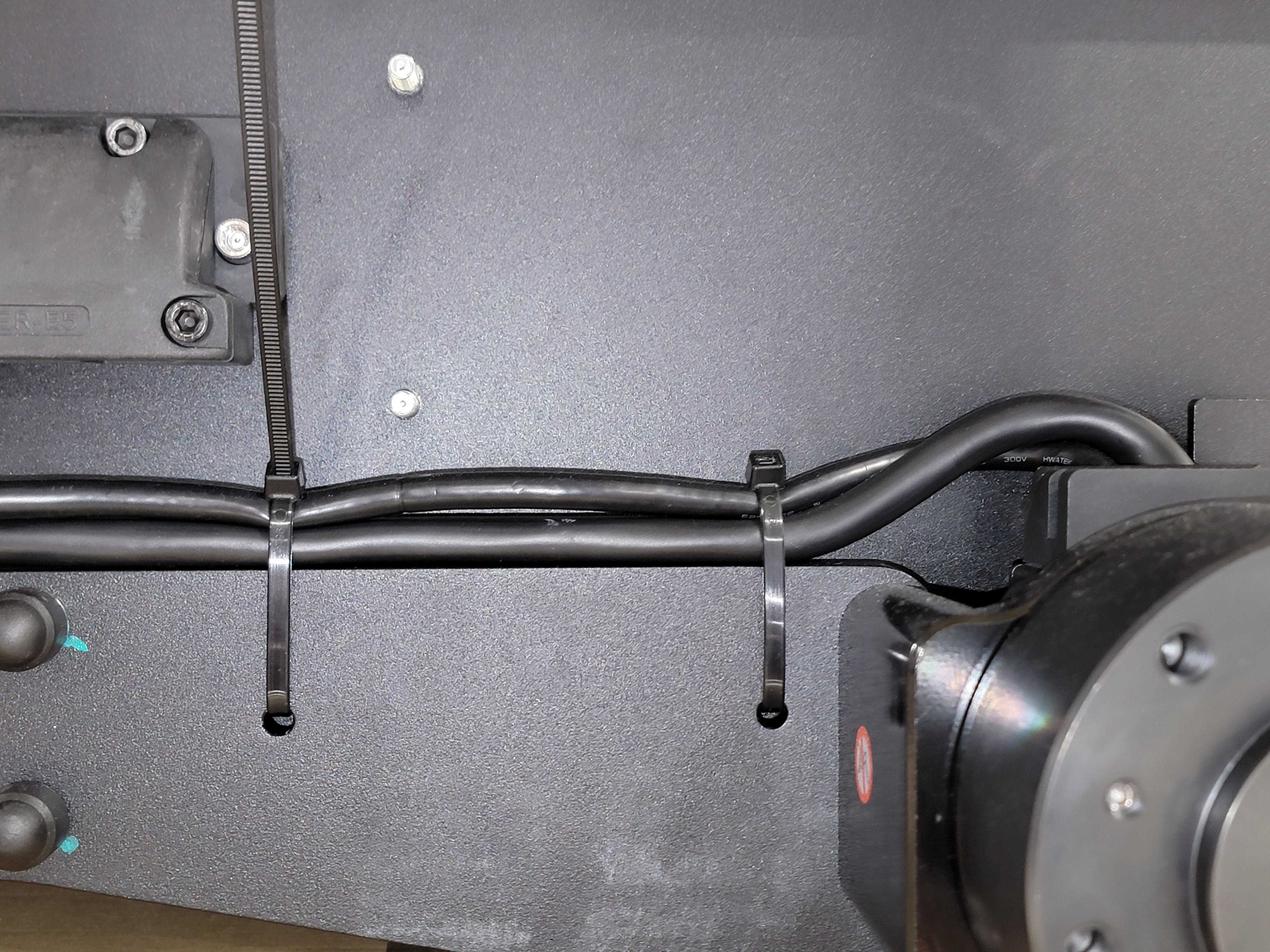
- Inspect the drivetrain for damage to any of the motor cables or to the cable ties that are used to secure the motor cables to the suspension beam. Check that there is clearance between the motor cables and the tires.
- Inspect the air filter.
- Clean any optical sensors.
- Turn the robot on, and check the battery's State-of-charge.
- Disconnect the battery charger from the robot.
- Check that all of the Emergency Stop devices are functioning, including the Rear Charge Port Door, and the optional Wireless Emergency Stop Transmitter.
- Check that the robot has connected to your worksite's wireless network.
- Confirm that the robot computer has enough storage for any ROS bags that you plan to acquire during the robot's mission.
Robot Network Connection
Husky provides several network connection options, the details of which are outlined below.
Connecting to Husky over an Ethernet Connection
Husky can always be accessed over an Ethernet connection, following the steps below.
- Open the Rear Charge Port Door on Husky to expose the debug Ethernet port.
- Connect an Ethernet cable from Husky's debug Ethernet port to your laptop.
- Set your laptop's IP address and netmask as shown below.
- IP Address: 192.168.131.100
- Netmask: 255.255.255.0
- Confirm that you can ping Husky from your laptop's terminal window in Linux or the
command prompt in Windows by entering the following command:
ping 192.168.131.1The output should be similar to the following.Pinging 192.168.131.1 with 32 bytes of data:
Reply from 192.168.131.1: bytes=32 time<1ms TTL=128
Reply from 192.168.131.1: bytes=32 time<1ms TTL=128
Reply from 192.168.131.1: bytes=32 time<1ms TTL=128
Reply from 192.168.131.1: bytes=32 time<1ms TTL=128
Ping statistics for 192.168.131.1:
Packets: Sent = 4, Received = 4, Lost = 0 (0% loss),
Approximate round trip times in milli-seconds:
Minimum = 0ms, Maximum = 0ms, Average = 0ms - Connect to your laptop to the robot using SSH. To do so, execute the following in a terminal window:
You will be prompted to enter a password. The default password is
ssh robot@192.168.131.1clearpath.noteAll Clearpath robots ship from the factory with their login password set to
clearpath. Upon receipt of your robot we recommend changing the password. To change the password, run the following command on the robot:passwdThis will prompt you to enter the current password, followed by the new password twice. While typing the passwords in the
passwdprompt there will be no visual feedback (e.g.*characters).
Connecting to Husky AMP's Wi-Fi Access Point
As an alternative to connecting over Ethernet, it is always possible to connect to Husky AMP's Wi-Fi access point, following the steps below.
- Use your laptop to connect to Husky AMP's Wi-Fi network. The Wi-Fi network name (SSID) will be
cpr_a300_amp_XXXXX, whereXXXXXmatches the serial number of the Husky AMP. When prompted, use the passwordclearpath. - Confirm that your laptop's Wi-Fi network interface is configured to use DHCP and that it
has been assigned an IP address in the
192.168.131.XXXrange. - Confirm that you can ping Husky AMP from your laptop's terminal window in Linux or the
command prompt in Windows by entering the following command:
ping 192.168.131.1The output should be similar to the following.Pinging 192.168.131.1 with 32 bytes of data:
Reply from 192.168.131.1: bytes=32 time<1ms TTL=128
Reply from 192.168.131.1: bytes=32 time<1ms TTL=128
Reply from 192.168.131.1: bytes=32 time<1ms TTL=128
Reply from 192.168.131.1: bytes=32 time<1ms TTL=128
Ping statistics for 192.168.131.1:
Packets: Sent = 4, Received = 4, Lost = 0 (0% loss),
Approximate round trip times in milli-seconds:
Minimum = 0ms, Maximum = 0ms, Average = 0ms - Connect to your robot via SSH. To do so, execute the following in a terminal window:
ssh robot@192.168.131.1
Connecting Husky to a Wi-Fi Network
To get Husky AMP or Husky Observer connected to your local Wi-Fi network, follow the steps below.
- Connect your laptop to Husky's AMP network.
- In a web browser, open the configuration page for Husky's router: https://192.168.131.51
- Username:
admin - Default password:
Clearpath1
- Username:
- Click on either the
Wi-Fi WAN on 2.4 GHzorWi-Fi WAN on 5GHzlink, depending on whether you are setting up a 2.4 GHz or 5 GHz connection.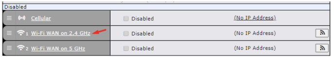
Select 2.4 GHz for configuration - On the new configuration page, scroll to the bottom; under
Wi-Fi Connection ProfilesclickCreate Profile.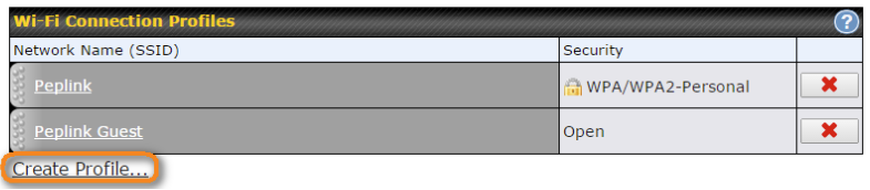
Create network profile - Enter the SSID and password for the network, then click OK.
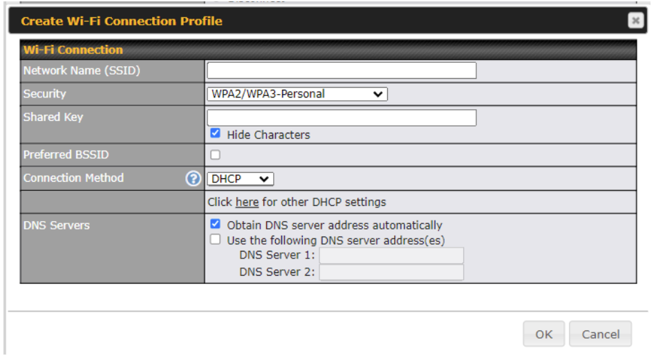
Configure network profile - Click
Save and Applyand wait for a message confirming that the configuration has been applied. - Click on the
Dashboardtab and confirm that the configured WAN connection reports asConnected.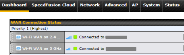
WAN Connection Status
For more advanced configurations, refer to the Wi-Fi WAN section of the
router's user manual.
Connecting Husky to a Cellular Network
To get Husky AMP or Husky Observer connected to a cellular network, follow the steps below.
- Install your SIM card into Husky's router by removing the Husky's
right side panel, removing the cover on the
Cellular SIMport on the router inserting the SIM card into slotA, and reinstalling the covers. - Connect your laptop to Husky's AMP network.
- In a web browser, open the configuration page for Husky's router: https://192.168.131.51
- Username:
admin - Default password:
Clearpath1
- Username:
- Click on the
Cellularlink.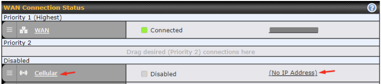
Select Cellular - On the new configuration page, complete the configuration as specified by your
cellular network provider. Ensure that the
Enabledcheckbox is clicked.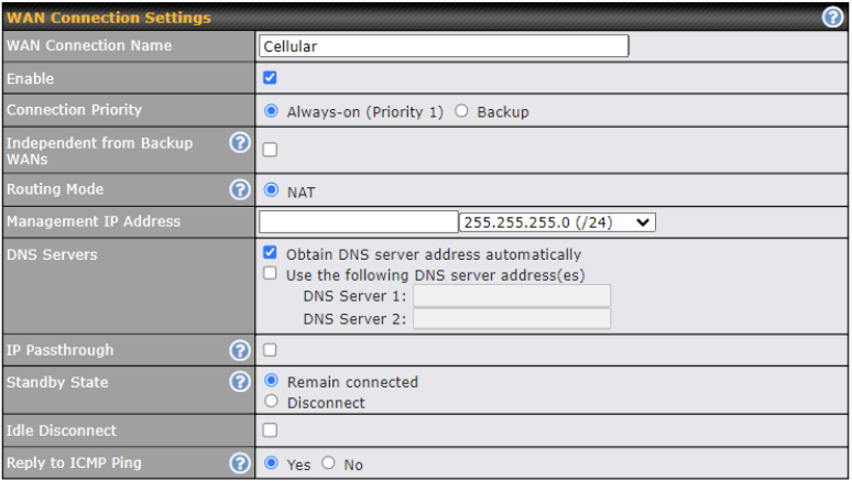
Cellular settings - Click
Save and Applyand wait for a message confirming that the configuration has been applied. - Click on the
Dashboardtab and confirm that theCellularconnection reports asConnected.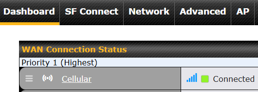
Cellular Connection Status
For more advanced configurations, refer to the Cellular WAN section of the
router's user manual.
Mobility Control
The Husky can be driven with these interfaces:
- Wireless Joystick
- ROS's command line interface with the
cmd_velROS 2 topic. - ROS's API, writing your programs in one of the ROS Client Libraries, like
rclcpporrclpy. - Using our OutdoorNav autonomy API, which is included in Husky AMP and Husky Observer.
You will use a ROS Client Libraries, like
rclcpporrclpy. - Using our OutdoorNav web user interface, which is included with Husky AMP and Husky Observer.
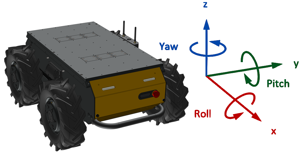
Orientation References
Husky's coordinate system is based on ISO 8855.
- Gravity is aligned with -Z.
- +X translational velocity will drive the Husky forward.
- The Husky can turn with ± Yaw.
Charging The Robot
The robot can be on or off while charging. To charge the Husky:
- Open the Rear Charge Port Door.
- Connect your Manual Charger to an AC outlet at your worksite.
- Plug the charger's red connector into the mating port on the back of the Husky.
The robot's batteries will not charge if the robot's circuit breaker is in the OFF position.
The Manual Charger has a light on it which confirms the robot's batteries are charging.
| Charger | Ready To Charge | Charging |
|---|---|---|
| Standard Charger, North America | 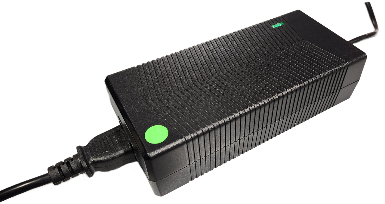 | 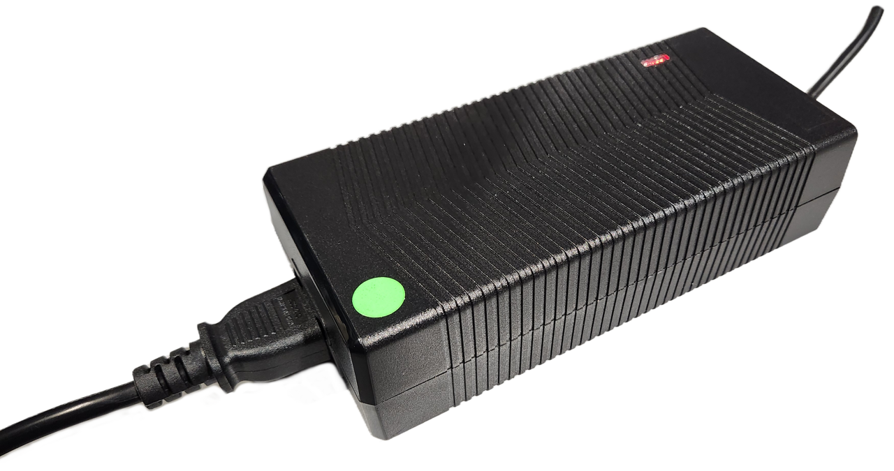 |
| Standard Charger, Europe | 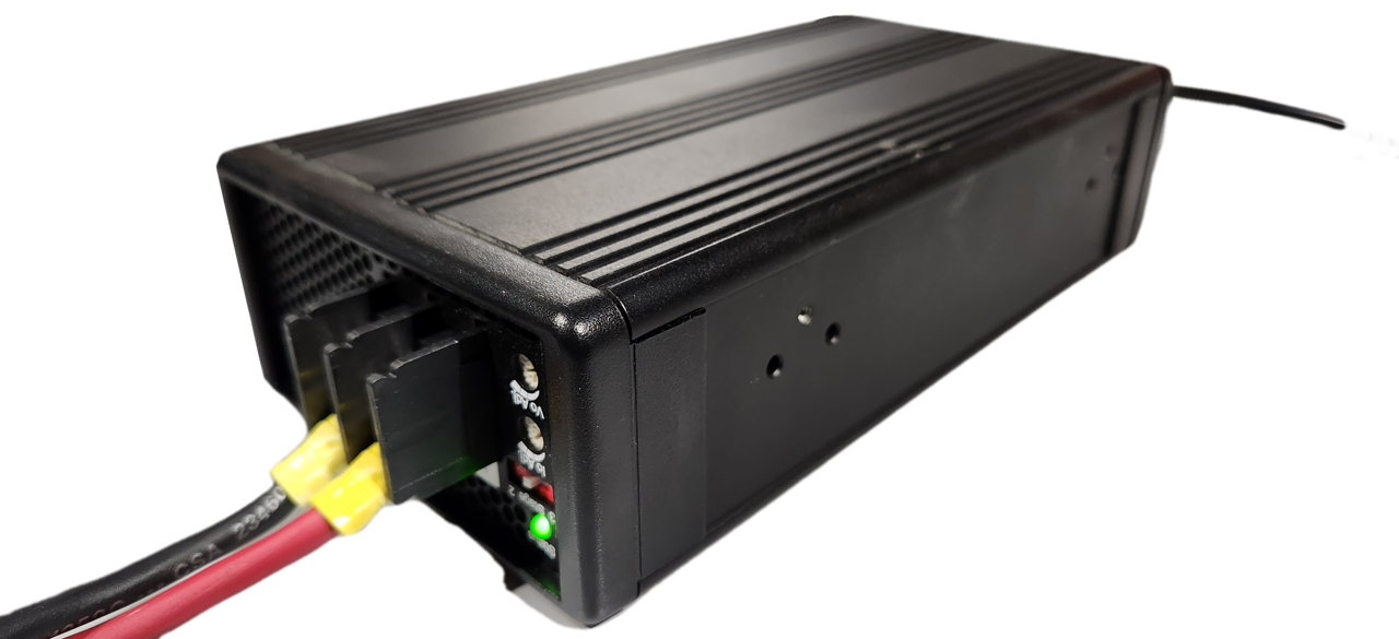 | 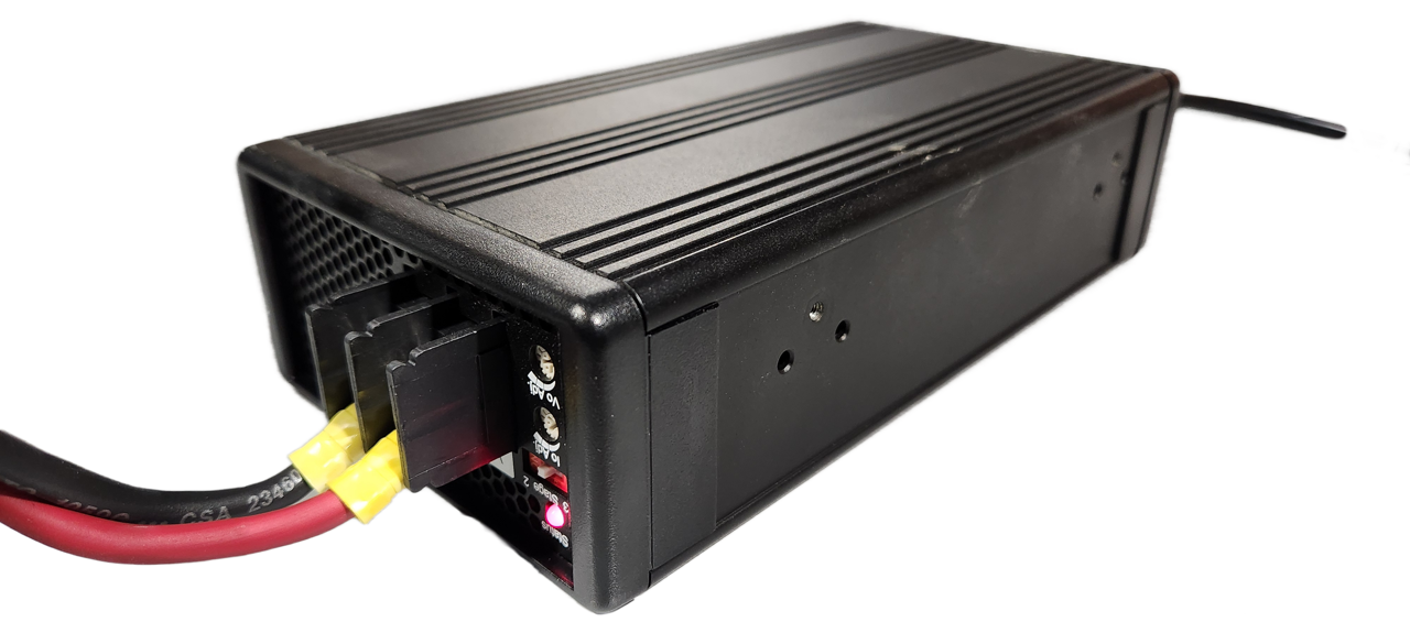 |
| Upgraded Charger1 | 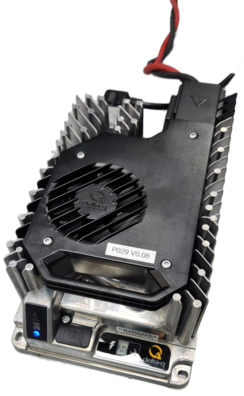 | 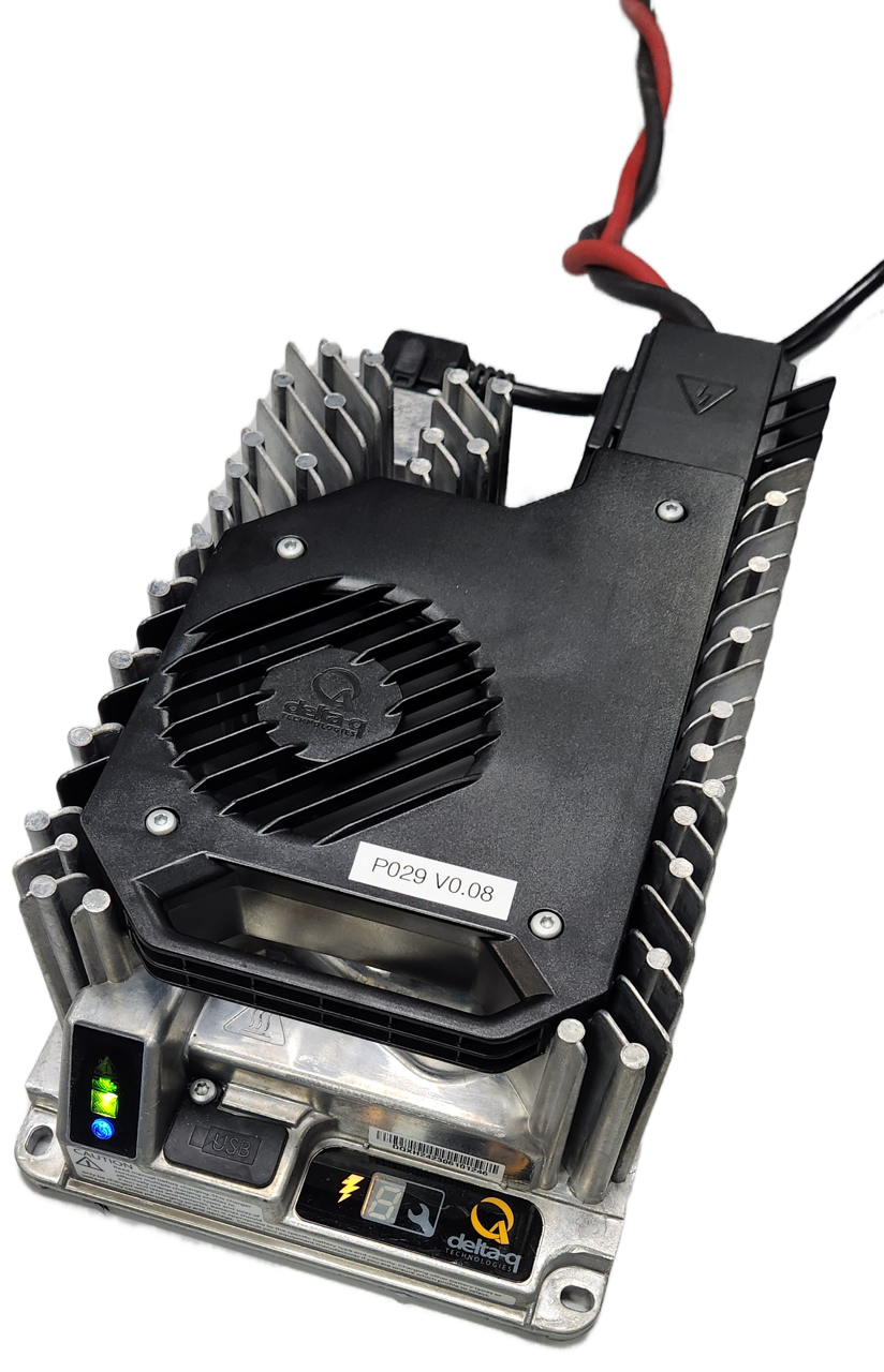 |
1 The images show our 1200 W Upgraded Charger. Our 650 W Upgraded Charger has the same light patterns to indicate charging.
The Husky's status lights should pulse to show that the batteries are charging. These lights may not show the charging pattern if the Husky is reporting a higher priority state—such as a Battery Fault. Refer to the Lighting page for details of all the robot states.
| Lighting State | Lighting Pattern |
|---|---|
| Charging |  |
| Charged |  |
The standard Manual Charger must be used in a dry environment. We sell a Fast Charger upgrade, which is waterproof. This Fast Charger can be used outdoors, as long as water is not entering the robot's Rear Charge Port area.
The included Wireless Charger can also be used in a wet environment, aligning with Husky's IP54 ingress protection rating.Wireless Charging

The Autonomous Wireless Charger is part of the Husky Observer. This includes:
- A stationary dock.
- A mobile charge coil on the robot.
- A 2D lidar for perceiving the stationary dock, allowing the robot to autonomously park near it to charge.
For the first time setup
- Place the Stationary Dock on flat and level ground. We intend the dock to be placed on a concrete slab. Concrete is ideal since it does not have potholes or other undulations that affect the robot's motion during docking.
- After placing the dock, connect it to main AC power. We configure the Stationary Dock's AC power cable for the destination country. The dock's electronics will power on.
- Drive your Husky towards the Stationary Dock. You should park the robot's Mobile Coil within 30 mm of the Stationary Coil to get the maximum charge rate. Charging will begin automatically when the robot is parked near the Dock's Stationary Coil. The Dock's fans will get louder as charging starts. if the Husky is on, the robot's Status Lights will show that the robot is charging.
The Dock will terminate charging when it detects the robot's batteries are charged. The Dock will continuously top up the batteries, so you can leave the robot near the Dock indefinitely. When you want to send the robot on a mission, just drive it away from the Dock—no need to tell the wireless charger to stop charging.
The OutdoorNav pages of our user manual explain how to setup docking, and then use it in missions.
The Autonomous Wireless Charger is an optional add-on for Husky AMP.
We sell the Wireless Charger add-on for base Husky A300 robots. This uses the same stationary dock and charge coil, but it does not include the lidar or OutdoorNav autonomy software. This allows you to manually drive the robot up to the dock, or configure your own perception sensors and autonomy software.
Talk to our Sales Team if you want to deploy a fleet of robots with wireless charging. We can unbundle the robots and docks, since fleets typically need more robots than docks.
Charging The Wireless Joystick
There is a micro-USB port on the top of the PS4 controller—near its LED. A USB cable was included in your robot's spare parts kit. Connect the controller to a computer, USB hub, or other 5 V USB charger. The controller's LED should glow yellow when it starts charging.

The Wireless Joystick will not send driving commands to the robot while the joystick is charging.
Charging The Wireless Emergency Stop Transmitter
This transmitter is part of the Wireless Emergency Stop upgrade kit for Husky.
- Remove the battery from the Wireless Emergency Stop Transmitter.
- Connect the charger's AC cable to an outlet at your worksite.
- Connect the transmitter's battery to the charger.
The robot's spare parts kit included a second battery for the transmitter.
Important System Limits
Diagnostics Monitoring
The Husky has protection software and hardware to reduce the chance of damaging components. For example, the motor controller's firmware will reduce the allowable mobility power if the motors are near their thermal limit.
You may want to monitor the Husky's /status and /diagnostics topics.
These topics provide useful information regarding voltages, currents, temperatures, and general health of the Husky.
Thermal Limits
Husky A300 is equipped with temperature sensors throughout the robot, which are used to monitor temperatures and determine fan speeds for proper cooling. System throttling may occur if the robot is approaching its critical thermal limits. Monitoring these fields over longer periods of operation will allow you to ensure that you are not putting excessive wear on Husky's motors and other components.
| Sensor | ROS Topic1 | Message Field | Lower Critical Limit, (°C) | Upper Critical Limit, (°C) | Notes |
|---|---|---|---|---|---|
| Motor [1-4] Temperature | /a300_00000/platform/motors/status | drivers[0-3].motor_temperature | -10 | 100 | Does not affect fan speed |
| Motor Driver [1-4] MCU Temperature | /a300_00000/platform/motors/status | drivers[0-3].mcu_temperature | -20 | 80 | |
| Motor Driver [1-4] PCB Temperature | /a300_00000/platform/motors/status | drivers[0-3].pcb_temperature | -20 | 80 | |
| Battery [1-6] Temperature | /a300_00000/bms/battery_state_[1-6] | temperature | -20 | 60 | Charging must occur above 0°C |
| MCU Temperature | /a300_00000/platform/mcu/status/temperature | temperatures[CC01_MCU] | -20 | 80 | |
| Fan Controller Temperature | /a300_00000/platform/mcu/status/temperature | temperatures[CC01_FAN[1-4]] | -20 | 80 | |
| 5V Inductor Temperature | /a300_00000/platform/mcu/status/temperature | temperatures[5V_INDUCTOR] | -20 | 80 | |
| Main Ground Lug Temperature | /a300_00000/platform/mcu/status/temperature | temperatures[MAIN_GND_LUG] | -20 | 80 | |
| 24V DC/DC Temperature | /a300_00000/platform/mcu/status/temperature | temperatures[24V_DCDC] | -20 | 80 | |
| 12V DC/DC Temperature | /a300_00000/platform/mcu/status/temperature | temperatures[12V_DCDC] | -20 | 80 |
1 Adjust the /a300_00000 field with the serial number of your robot.
You can find the serial number under the Front Panel, on the Nameplate.
Current Limits
| Husky AMP, 40 Ah | Husky AMP, 80 Ah | Husky AMP, 120 Ah | |
| Battery Continuous Current Output | |||
| Circuit Breaker Value | |||
| Motor Continuous Output1 | |||
1 Husky A300's motors are rated to draw 17 A continuous, but they will spike to several times higher than this, particularly when traversing rough terrain and when turning on the spot. To reduce current draw, consider commanding wider-radius turns from your control software.
Stability Limits
WARNING
Ensure that the robot's centre of mass will not result in tipping hazards due to driving on hills.
Your commissioning team needs to perform calculations to confirm the robot's centre of mass will remain within the robot's footprint across its operating terrain. Your calculations should include a safety margin.
Refer to the Technical Specifications for the safe operating limits when there is no payload on the Husky.
WARNING
Always account for variations in the target environment when determining safe operating conditions. Rain, snow, or ice in the operating environment may change the safe operating limits.
(Dimensions in mm)
The image below provides an example stability cone for Husky A300. It shows the location in which the centre of mass of a 100 kg payload must reside to avoid tipping while being able to operate at inclines up to ±30°, side slopes up to ±30°, and accelerations up to ±4 m/s². A safety factor should be applied so that the centre of mass is well inside the defined stability cone, especially when operating on uneven surfaces, on large inclines or side slopes, in varying friction environments , with low tire pressure, and worn treads.
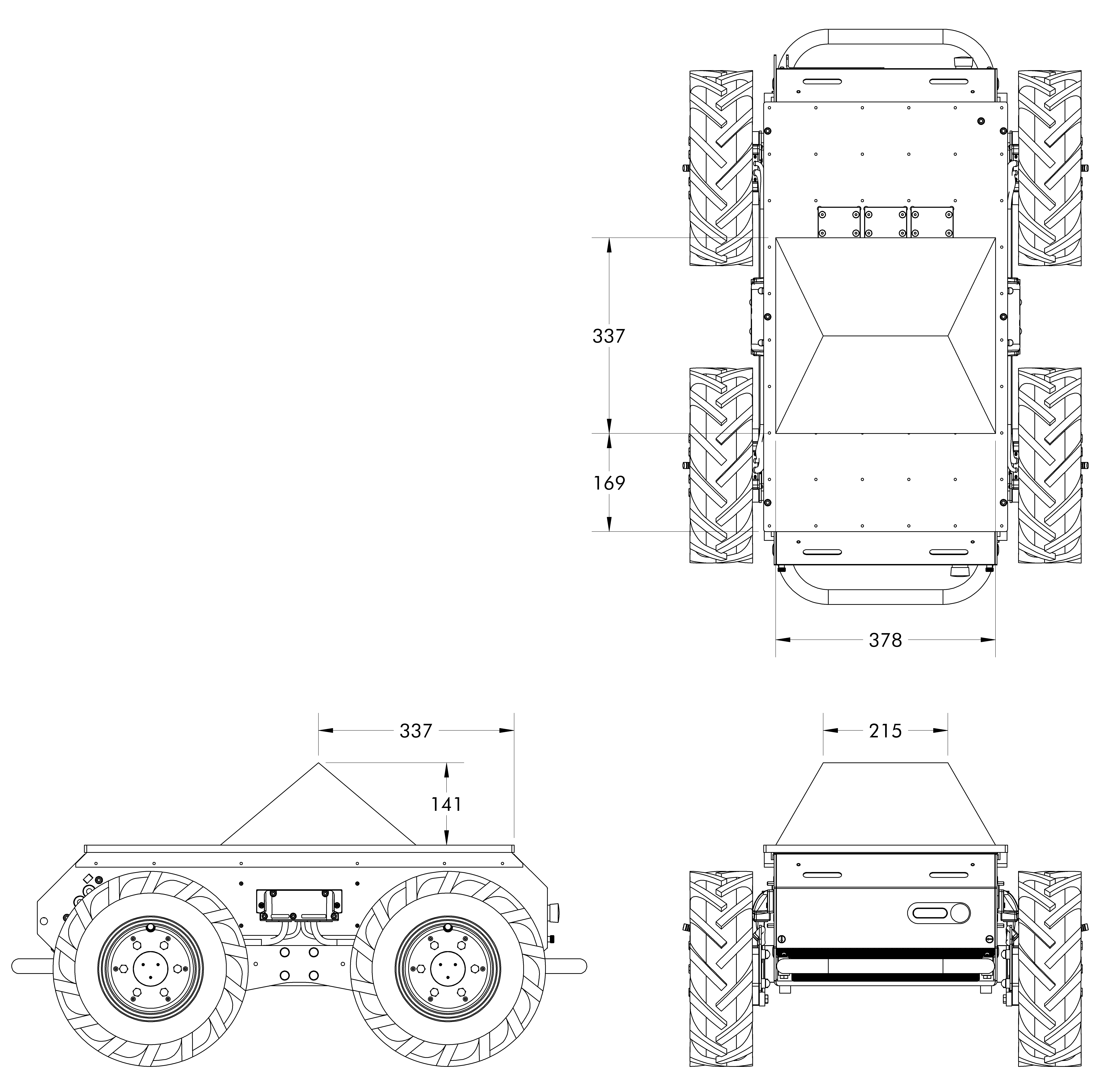
(Dimensions in mm)
This example was for a base Husky A300 with a 40 Ah battery. Using this example as a reference, you should make adjustments for your configuration, including:
- If your robot's battery is 40 Ah, 80 Ah, or 120 Ah.
- If your robot is a Husky AMP or Husky Observer.
- If your robot has custom sensors, manipulators, or payloads.
Refer to the Technical Specifications on this page for centre of mass values for the different battery configurations.
Emergency Stop Braking Limits
When Husky A300 has its Emergency Stop engaged, an electrical—(resistive)—brake is applied to reduce the speed of the robot. The payload mass and the incline on which the robot is operating will affect the terminal speed of the robot when the Emergency Stop is engaged.
WARNING
Always confirm terminal speeds in the target environment.
The performance values outlined below can be affected by various environmental factors such as terrain type and should be treated as a reference only. Exact limits should be determined by the user in the target operating environment. It is the responsibility of the user to ensure that no hazards are present in the target operating environment.
| Payload Mass | Incline | Terminal Speed1 |
|---|---|---|
| 0 kg | 0° | 0 m/s |
| 100 kg | 0° | 0 m/s |
| 0 kg | 15° | 0.5 m/s or less |
| 100 kg | 15° | 1.25 m/s or less |
The expected steady state rolling speed after pressing an Emergency Stop button. The resistive shunt brake increases in braking force linearly with the motor's speed.
Appropriate adjustments should be made for 80 Ah and 120 Ah configurations.
Stopping Distances
WARNING
Always confirm stopping distances in your operating environment.
The performance values outlined below can be affected by various environmental factors—(terrain type, wet or icy surfaces, gravel or other loose material)—and should be treated as a reference only. Your commissioning team should test to determine the limits in your operating environment.
The reported stopping distances are based on the default deceleration settings. This setting is configurable—(see ROS Parameters for details).
| Payload Mass | Incline | Surface Type | Stopping Distance |
|---|---|---|---|
| 0 kg | 0° | High friction | 0.5 m |
| 100 kg | 0° | High friction | 0.7 m |
| 0 kg | 15° | High friction | 0.5 m |
| 100 kg | 15° | High friction | 1.0 m |
Maintenance, Preventative
DANGER
Maintaining robots can be dangerous. There are hazards from high energy batteries, sharp edges, joints that can shear, and heavy items that can crush. The robot is intended to be maintained by a technician that is familiar with safe work procedures, and has experience using the required tools.
Technicians must read and understand this manual.
Technicians must review and understand their worksite's Risk Assessment and required procedures.
Contact our Support Team if you have any questions.
Lockout Tagout
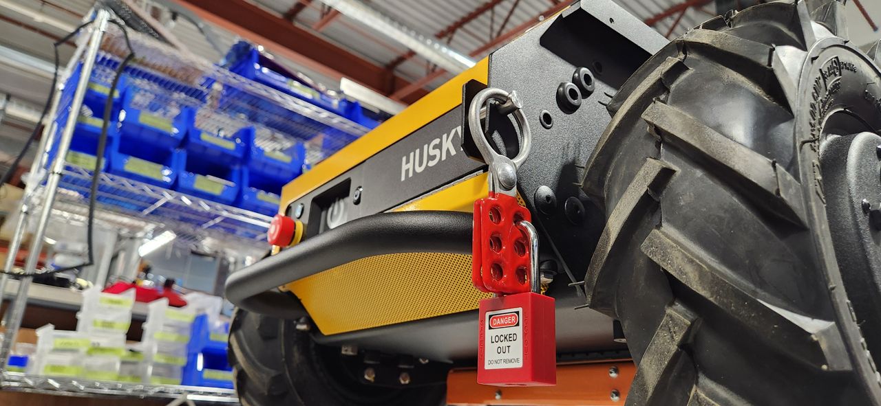
Lockout procedures remove potential energy from machines as we perform maintenance. This reduces risk of harm while performing maintenance. The Husky's main source of potential energy is the batteries. We cannot completely discharge these batteries without damaging them, but we can disconnect them from all the robot's electronics.
To disconnect the batteries, and lockout the machine:
- If applicable; move the Husky away from its Wireless Charger.
- Open the Husky's Rear Charge Port Door.
- Disconnect the Manual Charger.
- Flip the Circuit Breaker to the OFF position.
- Confirm that the robot will not turn on, by pressing and holding the ON-OFF button for 0.5 seconds.
Now that you have isolated the batteries; you can lockout the robot. We do this by closing the Rear Charge Port Door, and then locking it to the robot's chassis.
The lockout pin and scissors shown in the image are not included with a standard Husky order. Any pin or hasp that prevents the Rear Charge Port Door from opening should be acceptable.
If you want the same hardware shown in this image, contact Clearpath's Support Team, and ask about the Lockout Kit—032200.
Follow the guidance below while performing maintenance to ensure that the system is in a safe state following any maintenance work on the robot.
- Clean up all tools and ensure that no tools or installation materials have been left inside the robot.
- Ensure that all cables have been tightened to the specified torque values and that there are no loose or unconnected cables.
- Reinstall any fuse covers that were removed.
- Restore all terminal boots to their original position prior to maintenance.
Once all parts have been reinstalled and maintenance is completed, perform the following system checks:
- Power on the robot.
- Place the robot up on blocks and confirm that each source of an emergency stop can be used to trigger the emergency stop condition by:
- confirming that the joystick can be used to make the wheels spin
- engaging the stop condition
- confirming that the corner lights go into a flashing red light pattern
- confirming that the joystick can no longer make the wheels spin
- disengaging the stop condition
- pressing the restart button
- confirming that the corner lights return to the normal driving pattern
- confirming that the joystick can be used to make the wheels spin again.
notePerform this check of emergency stop functionality individually for each of:
- Front Emergency Stop Button
- Rear Emergency Stop Button
- Rear Charge Port Door
- Wireless Emergency Stop Button (if present)
- Additional Emergency Stop Buttons (if present)
- Connect the manual charger and charge the robot for at least 5 minutes. Confirm that the state of charge is increasing and that there are no unexpected sounds or smells.
- With the robot in an open area at least 10 m in diameter and away from other people, connect the joystick and drive the robot for at least 30 seconds to confirm it is performing as expected.
Tire Pressure
The Husky's tires get filled through the Schrader valve stem. This stem is close to the rim, to avoid damage from door frames and other obstacles. Some air pumps' chucks are too large to seal against this Schrader valve.
We have included a Schrader valve extension in the Husky's spare parts kit.
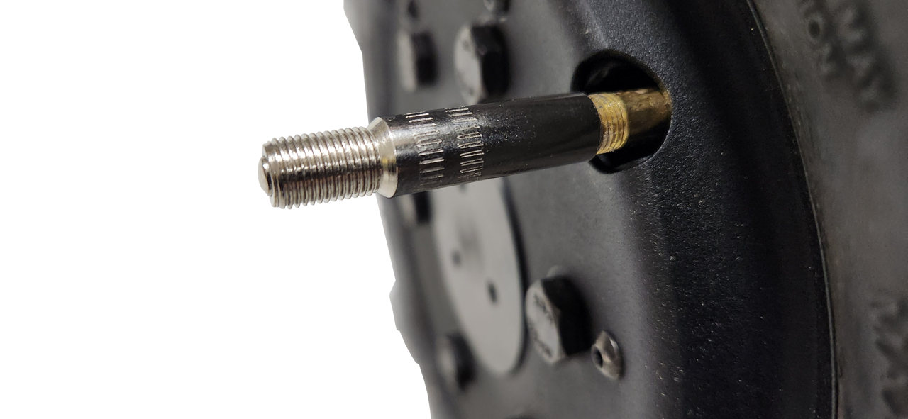
The Husky's tires should all be between 70 kPa to 140 kPa (10 psi to 20 psi).
We suggest 140 kPa for use cases on flat asphalt or concrete, to improve turning performance.
Lower tire pressures improve traction in rough and varied terrain, with rocks or other obstacles. Lower tire pressures also reduce the effective diameter of the wheel, which will increase the error of odometry readings. Odometry is calculated using the average diameter of a tire inflated to 137 kPa (20 psi).
Front Cover
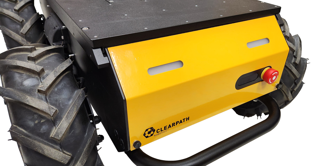
The Husky's identification labels, status lights, air filter, and some fasteners are located under the Front Cover.
To remove this cover:
Twist the 2 thumb-latches 90°, so the arrows are horizontal.
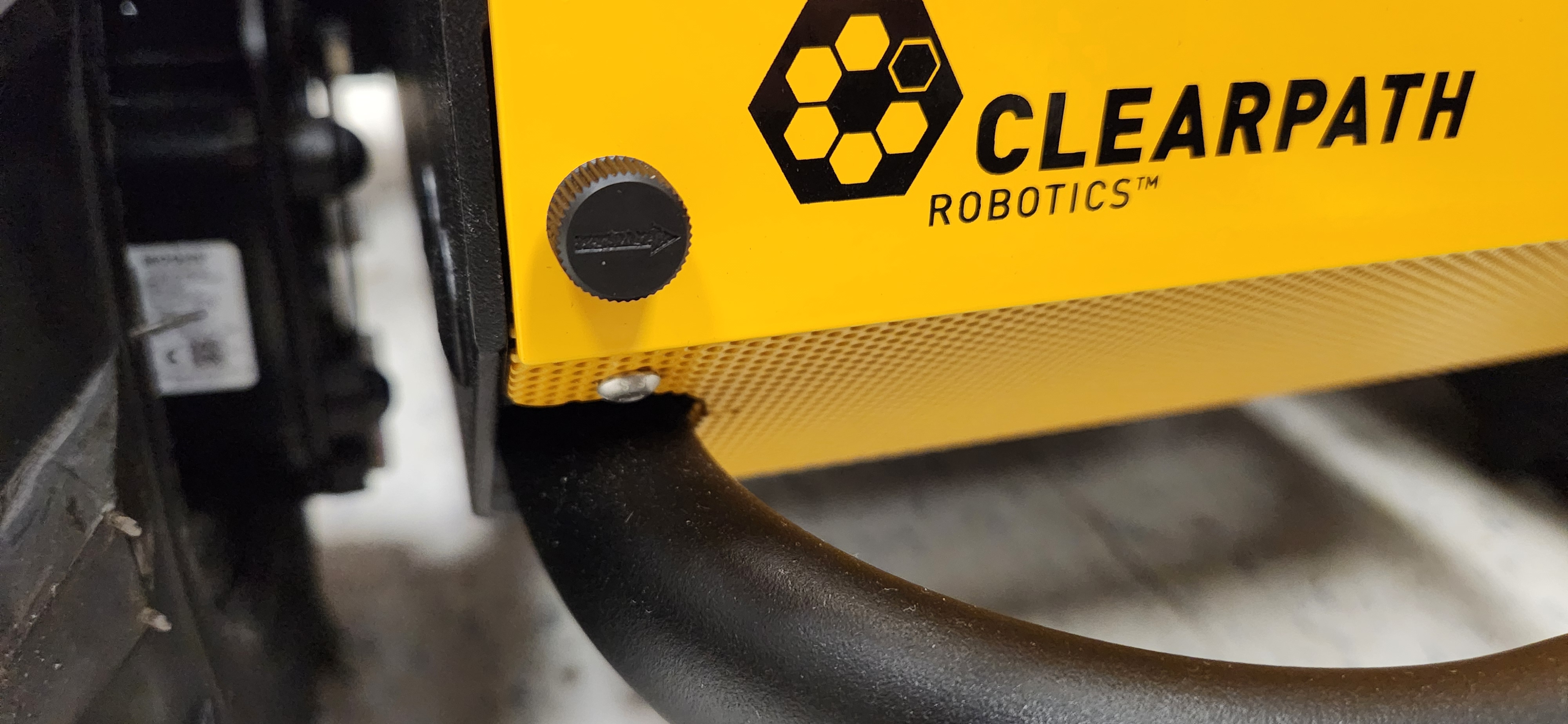
Tilt the cover.
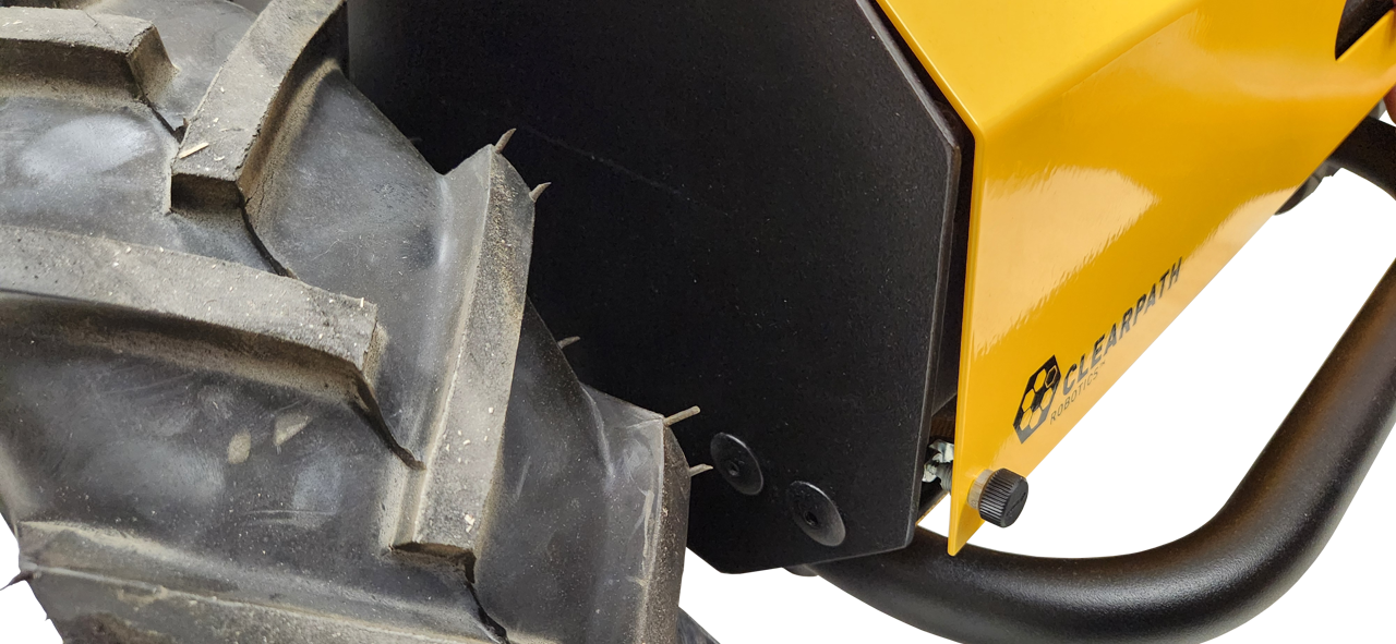
Lift the cover's pins from the chassis's 2 rubber grommets.
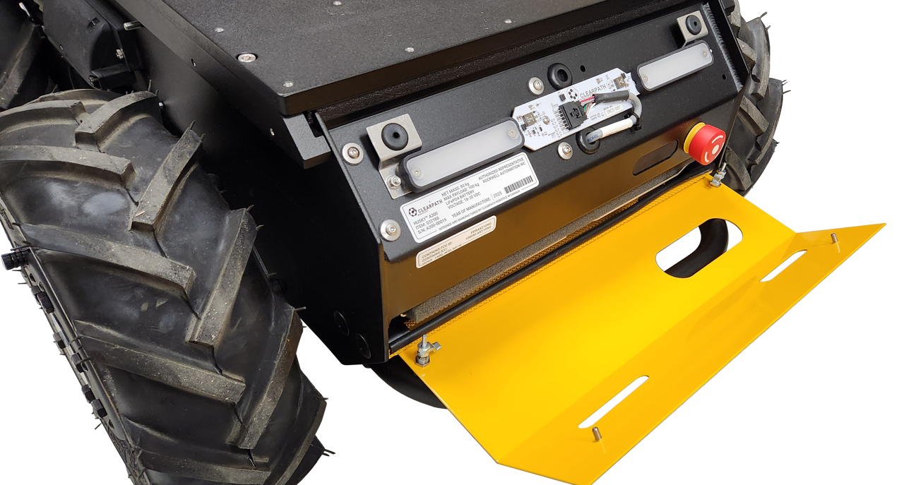
The cover must be installed during operations to maintain Husky's IP54 ingress protection rating, and reduce the risk of entrapment.
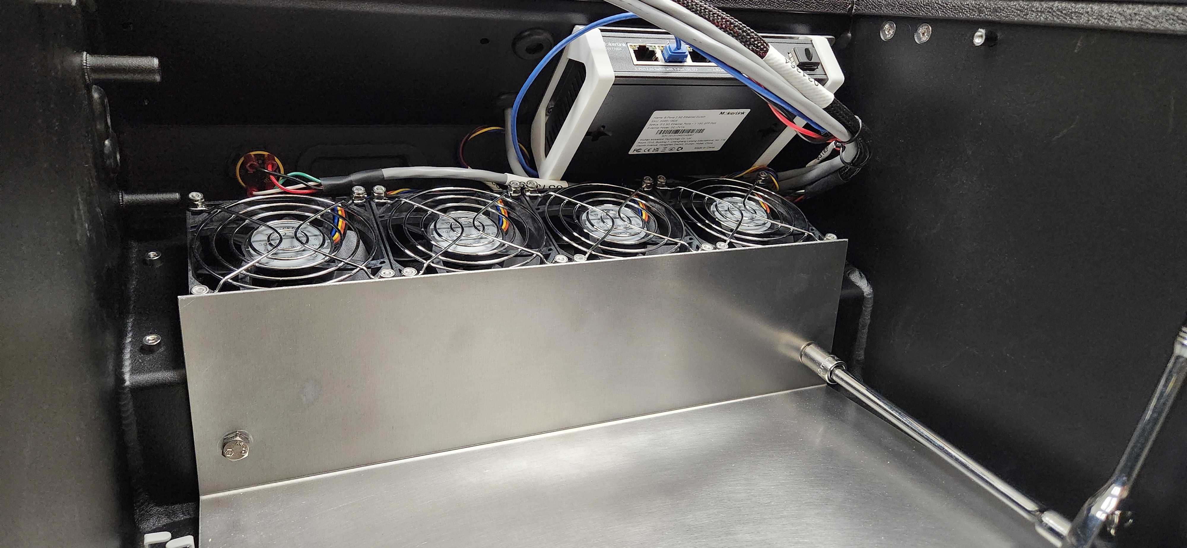
Air Filter
Husky includes four 80 X 80 mm fans to cool the internal electronics. The air passes through the Husky's Front Grille, then through the Air Filter, before reaching the fans.
After cooling the electronics, the air is exhausted through the Husky's Rear Grille.
To clean or replace the Air Filter:
Remove the Front Cover, as described in the section Removing The Front Cover
Grab the centre of the filter, and pull the filter out of the robot. There is a notch in the metal bracket to give you access.
Clean the filter with water.
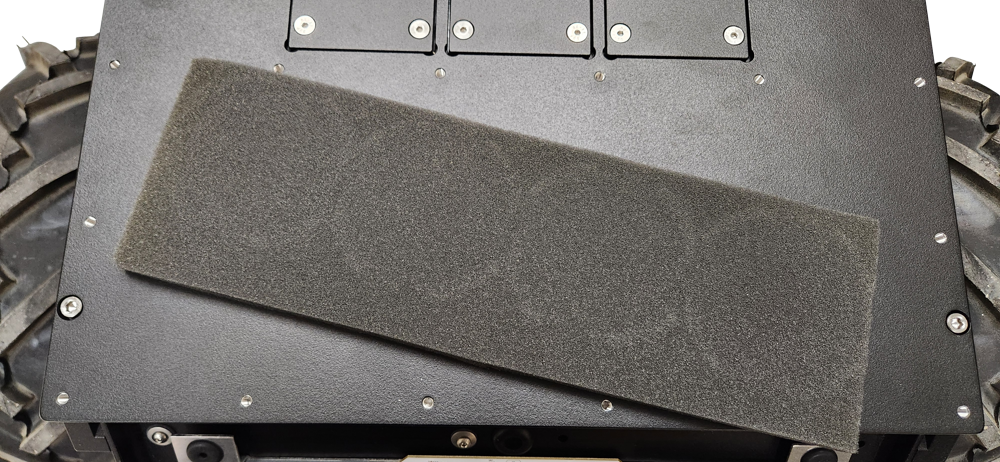
Return the filter when dry, or replace it with a new filter. The filter should be flush with the bare metal bracket.
Battery Cell Balancing
Husky is powered by LiFePO4 batteries. The function and health of these batteries is monitored by a Battery Management Unit—(BMU)—which is internal to each of the battery packs.
Over the operating life of Husky, the State of Charge—(SoC)—of the batteries may start being misreported, accompanied by a higher voltage difference between the batteries' cells. Ideally; battery cells should be within a range of 50 mV. If the cell voltage difference is larger than 50 mV; Husky's batteries may suddenly drop in SoC while operating, or the Husky may unexpectedly shut off.
You should cell balance the batteries at least once per week to avoid this issue.
- Place the robot on a level surface.
- Power off the robot.
- Confirm the robot's circuit breaker is in the On position.
- Connect the manual charger.
- Let the batteries charge for at least 12 hours.
The intention of the Battery Cell Balance is to reach 100% SoC, and then charge for an additional hour while the robot is off. The suggested charge times above may be shorter if:
- Husky's batteries are already close to 100% SoC,
- Or you are using an upgraded manual charger.
Emergency Stop Braking Inspection
We suggest a daily Pre-Operation Inspection that all the Emergency Stop buttons are functioning. The Braking Inspection detailed here is to confirm that the stopping distance is within the expected range. We suggest you perform this inspection at least once per year, to confirm that the electrical braking systems components and connections have not worn to an unacceptable level.
- Remove any payload from your robot.
- Turn the robot on.
- Find a 10 metre stretch of flat ground. At the 5 metre point, mark the ground with a braking test starting point.
- Drive the robot at 1 m/s.
- Press an Emergency Stop button as the robot's front tire touches the braking test mark.
- Measure the braking distance from the mark, to the stopped position of the front tire. Confirm that the stopping distance was less than 40 cm.
Contact our Support Team if the stopping distance was more than 40 cm.
Maintenance, Base Husky A300
DANGER
Maintaining robots can be dangerous. There are hazards from high energy batteries, sharp edges, joints that can shear, and heavy items that can crush. The robot is intended to be maintained by a technician that is familiar with safe work procedures, and has experience using the required tools.
Technicians must read and understand this manual.
Technicians must review and understand their worksite's Risk Assessment and required procedures.
Contact our Support Team if you have any questions.
Common Replacement Items
This does not cover the full bill-of-materials for your robot. These items are things we consider critical, so you may want to keep spares on hand. You can get any replacement part by contacting support@clearpathrobotics.com, including parts not listed here.
| Description | What Subsystem Is This Used In? | CPR Item | Manufacturer | Manufacturer Item | Maintenance Procedure |
|---|---|---|---|---|---|
| Fuse, 3A | System Interface Assembly (F2, F3, F4, F5, F8) | - | Littelfuse | 0453003.MR | Replacing board mount fuses |
| Fuse, 5A | System Interface Assembly (F6, F10) | - | Littelfuse | 0454005.MR | Replacing board mount fuses |
| Fuse, 8A | System Interface Assembly (F7, F9) | - | Littelfuse | 0453008.MR | Replacing board mount fuses |
| Fuse, 10 A | System Interface Assembly (F52, F53, F54, F55, F56, F57, F58) | - | Littelfuse | 0297010.WXT | Replacing blade mini fuses |
| Fuse, 10 A | System Interface Assembly, and System Interface Assembly's Standby Power Cable | 018897 | Littelfuse | 0297010.WXNV | Replacing blade mini fuses |
| Fuse, 20 A | System Interface Assembly | 032295 | Littelfuse | 0297020.U | Replacing blade mini fuses |
| Fuse, 40 A | Power Distribution's Large VBAT Contactors | 023567 | Littelfuse | 142.5631.5402 | Replacing BF1 fuses |
| Fuse, 50 A | Power Distribution's Manual Charger | 029139 | Littelfuse | 142.5631.5502 | Replacing BF1 fuses |
| Fuse, 60 A | Batteries, Power Distribution's Mobility Contactors, Power Distribution's Shunt Brake | 029140 | Littelfuse | 142.5631.5602 | Replacing BF1 fuses |
| Fuse, 150 A | Batteries | 029145 | Littelfuse | 142.5631.6152 | Replacing BF1 fuses |
| Air Filter | Fans | 032403 | Clearpath Robotics | - | Air Filter Maintenance |
| Tire | Mobility | 000269 | Carlisle | 5100201 | Tire Maintenance |
| Tire's Inner Tube | Mobility | 000435 | Carlisle | 323790 | Tire Maintenance |
Critical Items
These items are unlikely to fail in normal use. We are providing this data because some customers want spares on hand for anything that could impact their schedule.
| Description | What Subsystem Is This Used In? | CPR Item | Manufacturer |
|---|---|---|---|
| Battery | Batteries | 025047 | Clearpath Robotics |
| Battery Manual Charger | Spare Parts | 032729 | Clearpath Robotics |
| Main PCBA | System Interface Assembly | 030449 | Clearpath Robotics |
| BLDC Motor Controller PCBA | System Interface Assembly | 030377 | Clearpath Robotics |
| Common Core PCBA, (MCU) | System Interface Assembly | 030446 | Clearpath Robotics |
| 12 V DC-DC PCBA | System Interface Assembly | 030430 | Clearpath Robotics |
| 24 V DC-DC PCBA | System Interface Assembly | 030433 | Clearpath Robotics |
| Gearmotor | Mobility | 031514 | Clearpath Robotics |
| Fan | Fans | 031356 | Clearpath Robotics |
| Computer | Computer | 032741, or 032742 | Clearpath Robotics |
| Network Switch | Network Switch | 033443 | Clearpath Robotics |
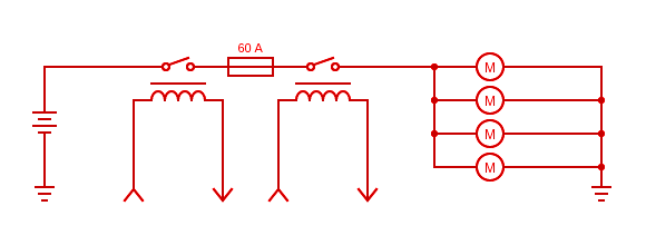
Wiring Diagram
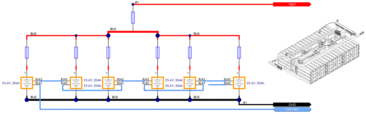
Wiring diagrams help diagnose the cause of issues, such as damaged cables or loose connections. This wiring diagram lists Clearpath's 6 digit item numbers for circuit boards and cables. The diagram does not include pinouts for individual cables.
Please contact our Support Team if you need more debugging information, or want a replacement cable.
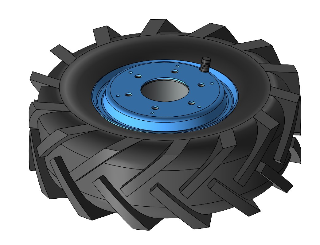
Tire and Inner Tube
CAUTION
Place the robot up on blocks prior to replacing the tire or inner tube. The robot may tip over if you remove a wheel without stabilizing the chassis.
To replace the tire and inner tube:
-
Shut off the robot's circuit breaker.
-
Remove the six M8×1.25 screws holding the wheel to the motor.
-
Deflate the tire by pressing on the Schrader valve's core.
-
Remove the six M4×0.7 screws and nuts that hold the split rim together.

-
Remove the outer rim.
-
Remove the tire and tube from the inner rim.
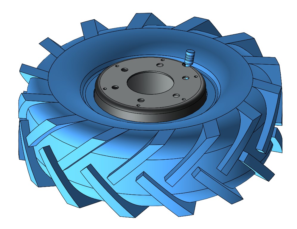
-
Replace the tire and/or tube as needed with new parts. Make sure the tire's chevron treads are facing the correct direction, as the left and right wheels have different tread orientations. Ensure that the tube is installed in the tire and inflated only far enough that it takes its shape. Inflating further will make reassembly difficult.
-
Place the tire—(with inner tube)—onto the inner rim, aligning the valve stem with the notch in the rim.
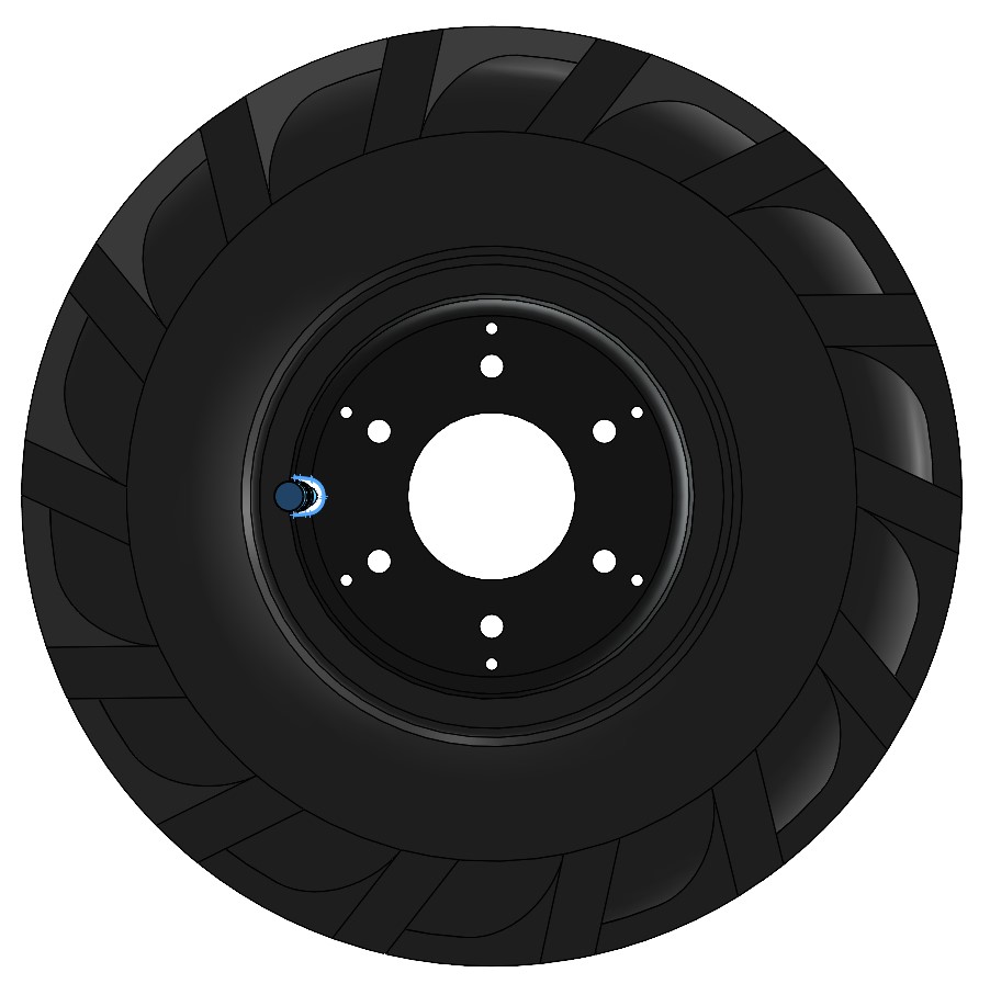
-
Place the outer rim on top, aligning the value stem with the notch in the rim.

-
Reinstall the six M4×0.7 screws and nuts, tightening them in a star pattern to 2 N·m.
noteIt may be necessary to use three longer M4×0.7 screws on a temporary basis to help pull the inner and outer rims together and ensure alignment, allowing the first three standard M4 screws to be installed. Then, the temporary M4×0.7 screws can be removed and the standard ones installed. As you tighten the screws, ensure that the valve stem is not being pinched.

-
Inflate the tire to 140 kPa (20 psi).
-
Place the wheel on the motor and reinstall the six M8×1.25 screws, tightening them in a star pattern to 20 N·m.
Motors
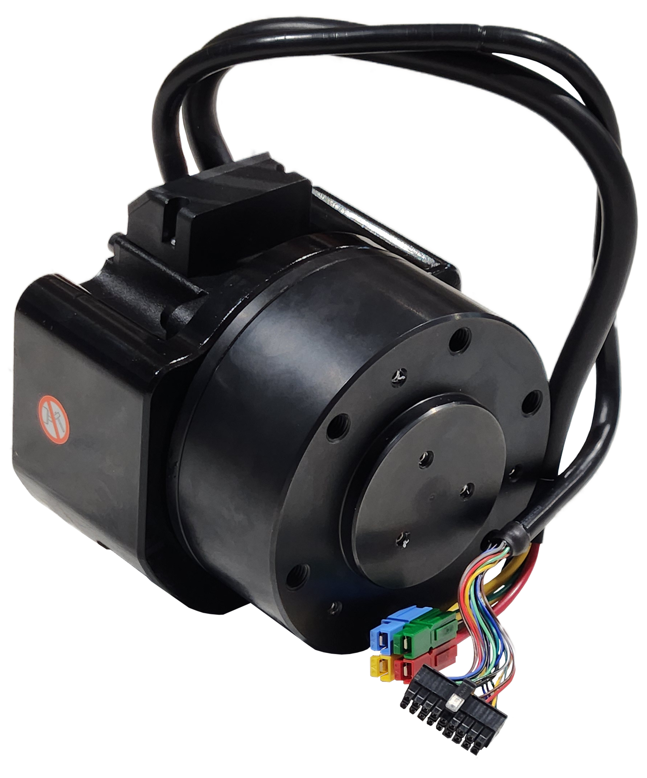
To remove the motors:
- Shut off the robot's circuit breaker.
- Remove the cable gland cover on the side of the robot. This cover is held with 5 socket head screws.
- Disconnect both sets of motor power and cables from the chassis on the side of the robot with the motor being replaced. The thick power cables are removed by pulling on the cable. The thinner data cables have a latch on the connector; press on the latch and then pull on the connector.
- Remove the suspension beam from the chassis by removing the four nuts and washers.
- Remove the wheel from the motor (see above).
- Remove the motor from the suspension beam by removing the four M8×1.25 screws.
When reinstalling the motor and suspension:
- Torque the motor's 4 screws to 20 N·m.
- Gently pull both motor cables away from the motor so that the cables are held tightly along the suspension beam.
- Ensure that both cables are routed along the top face of the suspension beam, and are laid out so that the thinner cable sits on top of the thicker cable.
- Insert an 11" black cable tie into the first hole in the suspension beam (the hole closest to the motor) and tie it around the cables as they are being held.
- Ensure that the cable tie is tightened as much as possible by hand, that both cables remain above the suspension beam, and the thinner cable remains on top of the thicker cable.
- Insert another 11" black cable tie into the second hole in the suspension beam (the hole closest to the center) and tie it around the cables.
- Ensure that the cable tie is tightened as much as possible by hand, that both cables remain above the suspension beam, and the thinner cable remains on top of the thicker cable.
- Cut off the extra length of both cable ties.
- Repeat above steps for each of the remaining three motors.
- Torque the wheel's 6 screws to 20 N·m.
- Torque the suspension beam's nuts to 30 N·m. Torque these slowly, in a star pattern. Exceeding 30 N·m will damage the Husky's aluminum chassis.
- Each motor has 2 cables. Make sure both related cables go to the related connectors on the robot's chassis.
- Torque the cable gland cover's screws to 1 N·m.
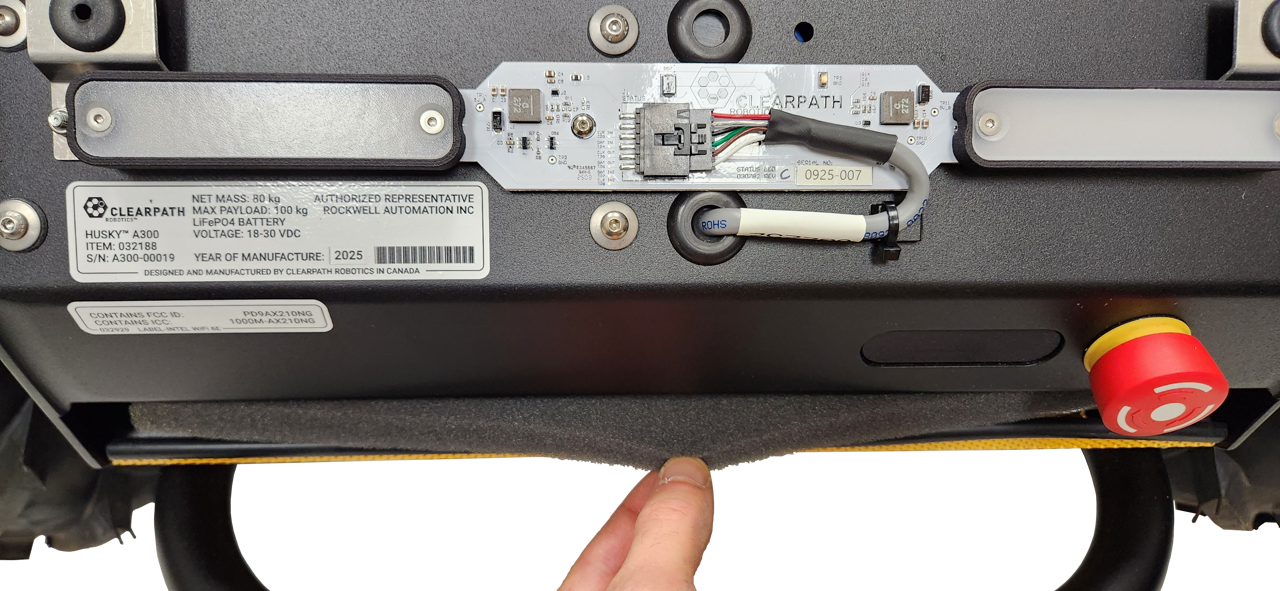
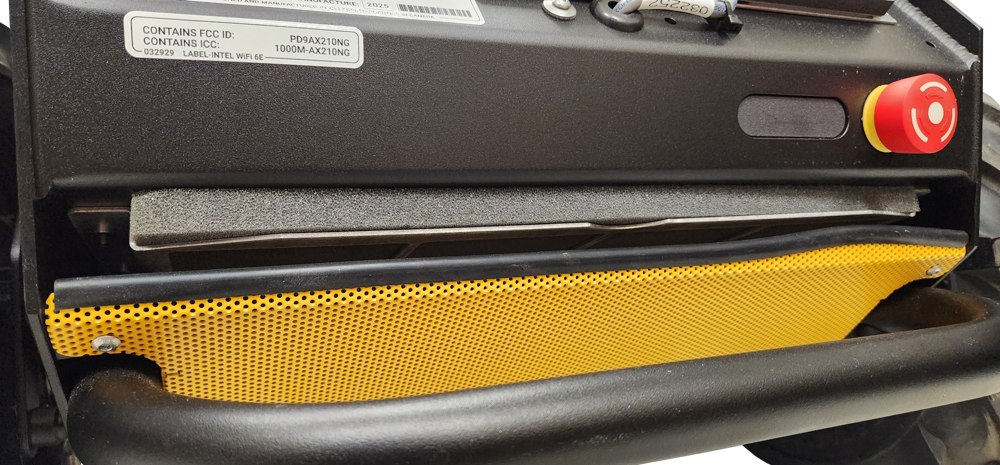
Nameplate And Regulatory
Husky's Nameplate is located under the Front Cover. The Nameplate includes regulatory marks, the product's name, serial number, and date of manufacture.
There will be other labels on the chassis with FCC information, such as the Intel Wi-Fi card shown in the attached image.
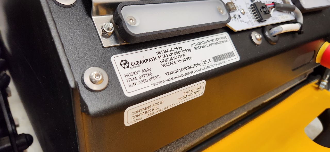
Our Removing The Front Cover section explains how to access the Nameplate.
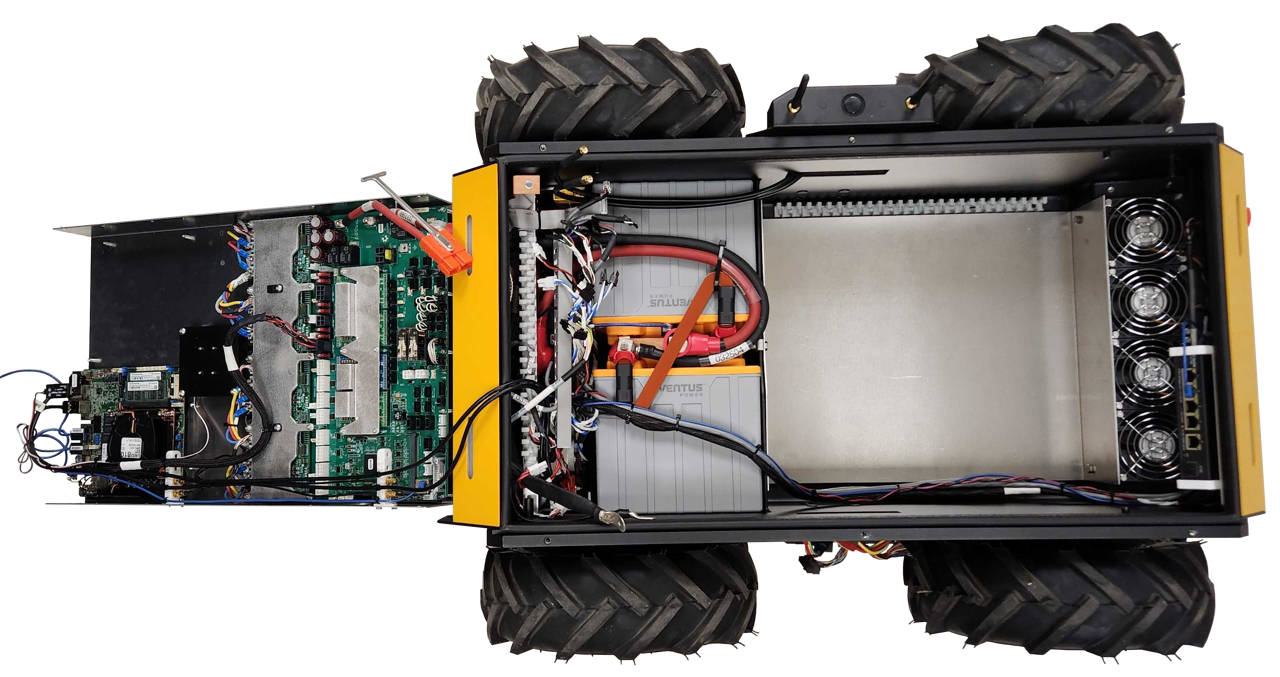
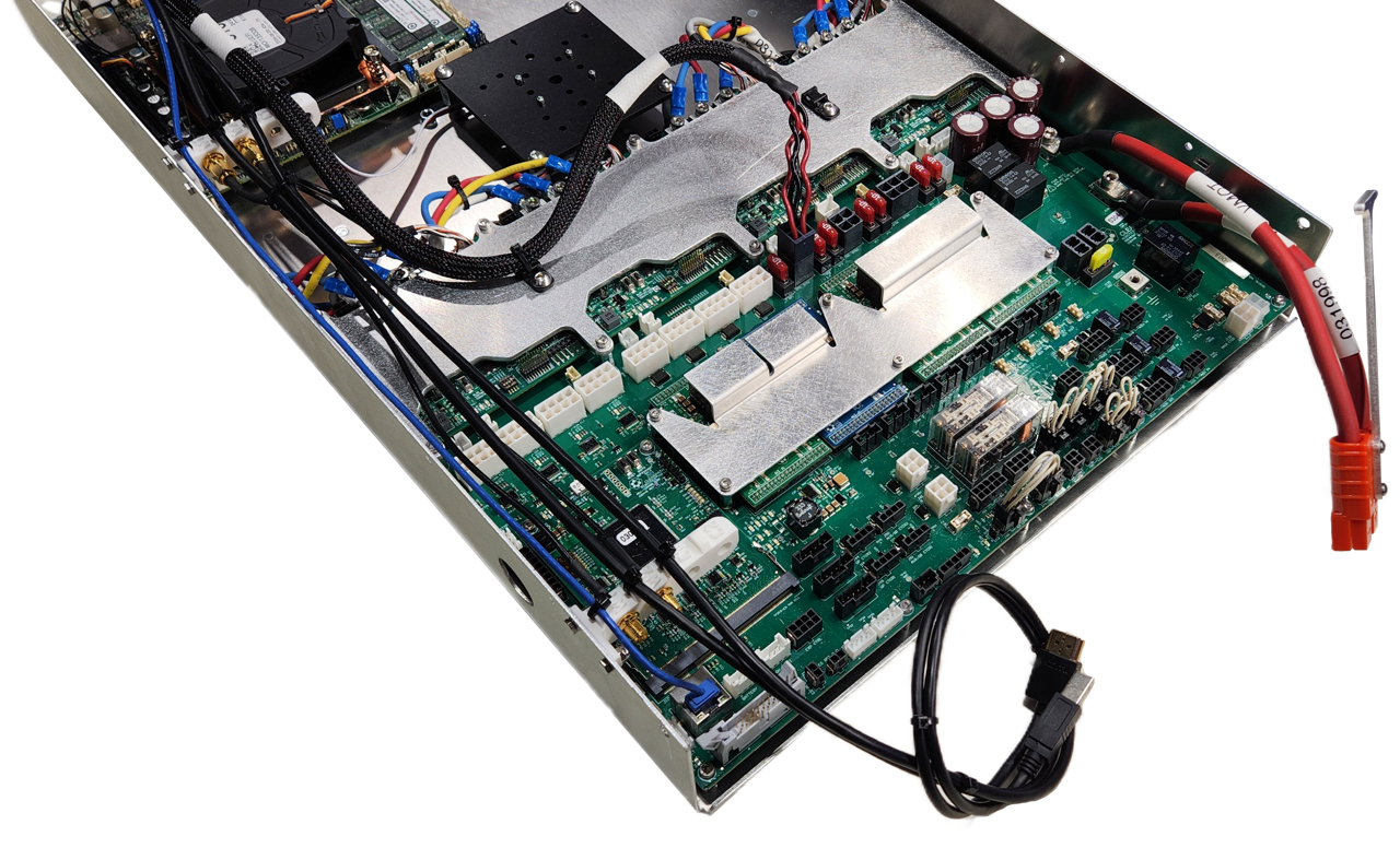
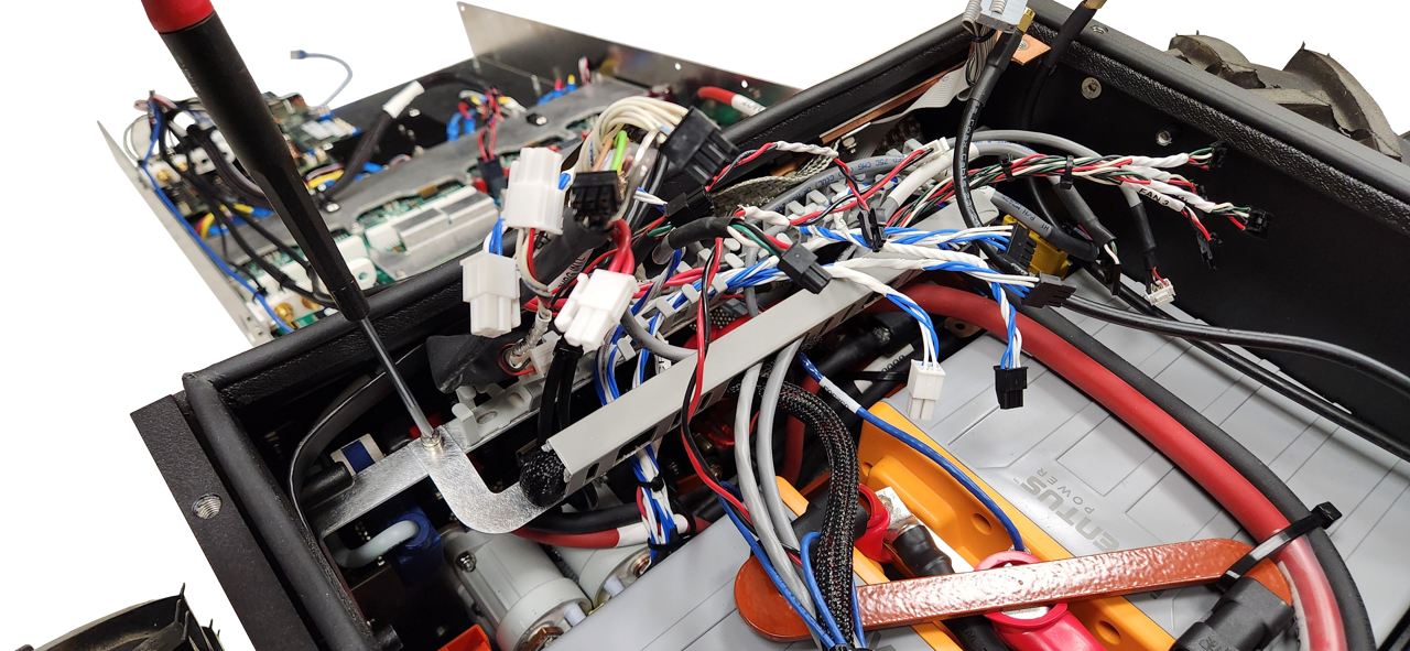
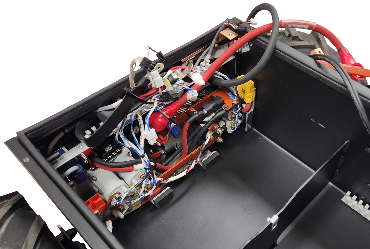
Electronics Tray
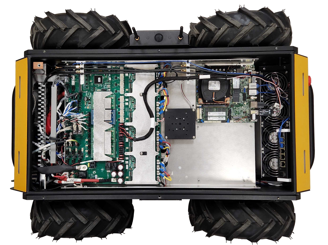
Once you have opened Husky's top, the first thing you see is the Electronics Tray. This tray includes the:
- Husky's System Interface Assembly circuit board
- Primary computer
- IMU
- Optional secondary computer or graphics card, (not shown in the image)
- Optional USB hub, (not shown in the image)
You may want to remove the Electronics Tray to access the integration bay under the tray, or to maintain Husky's Batteries and Power Distribution components.
Hinging The Electronics Tray
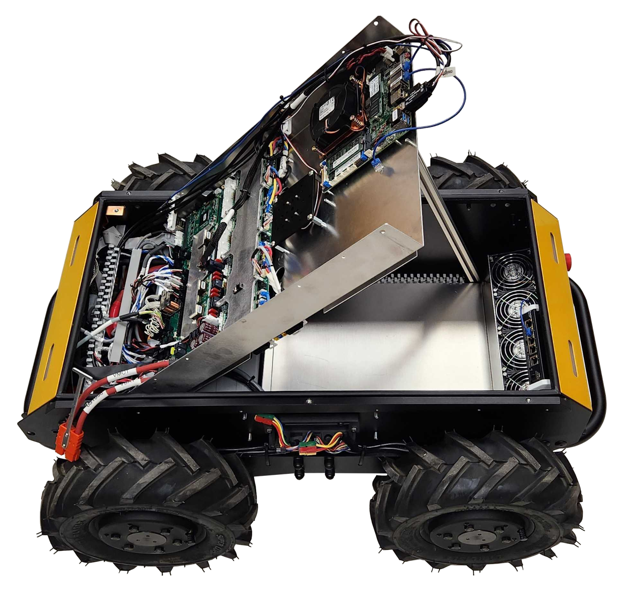
To hinge the tray:
- Shut off the Circuit Breaker
- Remove the Top Plate or Enclosure from the Husky
- Disconnect the motor cables, (2 per motor, so 8 cables total)
- Disconnect the computer's Ethernet cable from the network switch
- Disconnect the large orange connector near the rear-right of the robot. This connector provides main power, and mobility power to the Electronics Tray.
- Remove the tray's 2 front screws
- Loosen the tray's 2 rear screws, (these will become the tray's hinge pin)
- Lift the front of the tray
When reinstalling the tray:
- Torque the tray's 4 screws to 3 N·m.
Lifting the tray will expose Husky's batteries. The batteries's exposed +V terminals are always live, even when Husky's circuit breaker is in the Off position. The batteries are fused, but can still produce an electric arc if shorted to ground.
Wear protective equipment to guard your skin and eyes.
Keep the workspace clean, without any combustible materials nearby.
Review your workplace's safety procedures related to fires of LiFePO4 batteries.
Removing The Electronics Tray
To remove the tray:
-
Return the tray to the level position, (not hinged)
-
Take pictures of all the cables and connections to the System Interface Assembly. The cables have labels with names that match the PCBA's silkscreen, but pictures will help you reinstall these cables later.
-
Disconnect all the cables, (listed from the left side of the robot, towards the right):
- (Any cables from your custom integration)
- Front Ethernet cable to the network switch, (which should have been removed in the previous step)
- 2X Wi-Fi, (plastic bracket's W1 and W2)
- Current Sensor, (BATTERY I)
- HMI Display, (USER INTERFACE)
- Battery CANbus, (CAN_BAT)
- 2X Status Lights, (STATUS 1, STATUS 2)
- 2X Large VBAT Contactors, (UP CTCR1, UP CTCR2)
- 2X Shunt Brake Contactors, (AUX/SB CTCR1, AUX/SB CTCR2)
- 2X Mobility Contactors, (M CTCR1, M CTCR2)
- 4X Fans, (FAN 1, FAN 2, FAN 3, FAN 4)
- Optional, Wireless Emergency Stop Cable, (W ES)
- Wireless Emergency Stop Disable Keyswitch, (W ES BYP)
- 2X Emergency Stop Buttons, (ES1, ES2)
- Limit Switch, (CHRG INTL)
- Network Switch Power, (SYS4)
- Main Ground, (GND)
- Low Battery Shutdown, (CB KILL)
- Main Contactor, (MAIN CTCR)
- System Standby Power, (VSTBY)
- Tray Bond, (Tray's threaded stud, without identification)
- Leave the USB cable connected
- Leave the HDMI cable connected
- Large orange connector (V MOT and V SYS, which should have been removed in the previous step)
-
Remove the tray's 2 rear screws
-
Lift the tray out of the Husky. Note that the tray is still tethered to the Husky with a USB cable and a HDMI cable. Rotate the tray, and set it behind the Husky.
-
Disconnect the USB and HDMI cables from the Husky's Debug HMI area.
When reinstalling the tray:
- Torque the tray's 4 screws to 3 N·m.
- Torque the Main Ground cable's screw to 2.2 N·m.
- Torque the Tray Bond cable's nut to 3 N·m.
Battery Integration Tray
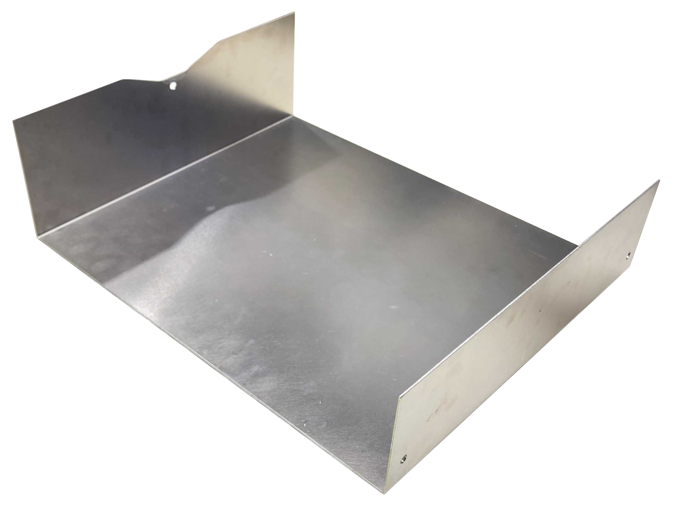
The Husky configurations with 40 Ah and 80 Ah batteries include a metal tray inside the chassis. You can mount your custom integration components on this tray.
The 120 Ah Husky fills the entire chassis volume with batteries.
To remove the tray:
- Remove the Electronics Tray, as it is blocking access to the battery volume.
- Remove the Battery Integration Tray's screws
- 3X screws for the 40 Ah Husky
- 2X screws for the 80 Ah Husky
- Remove the tray
When reinstalling the tray:
- Torque the tray's screws to 3 N·m.
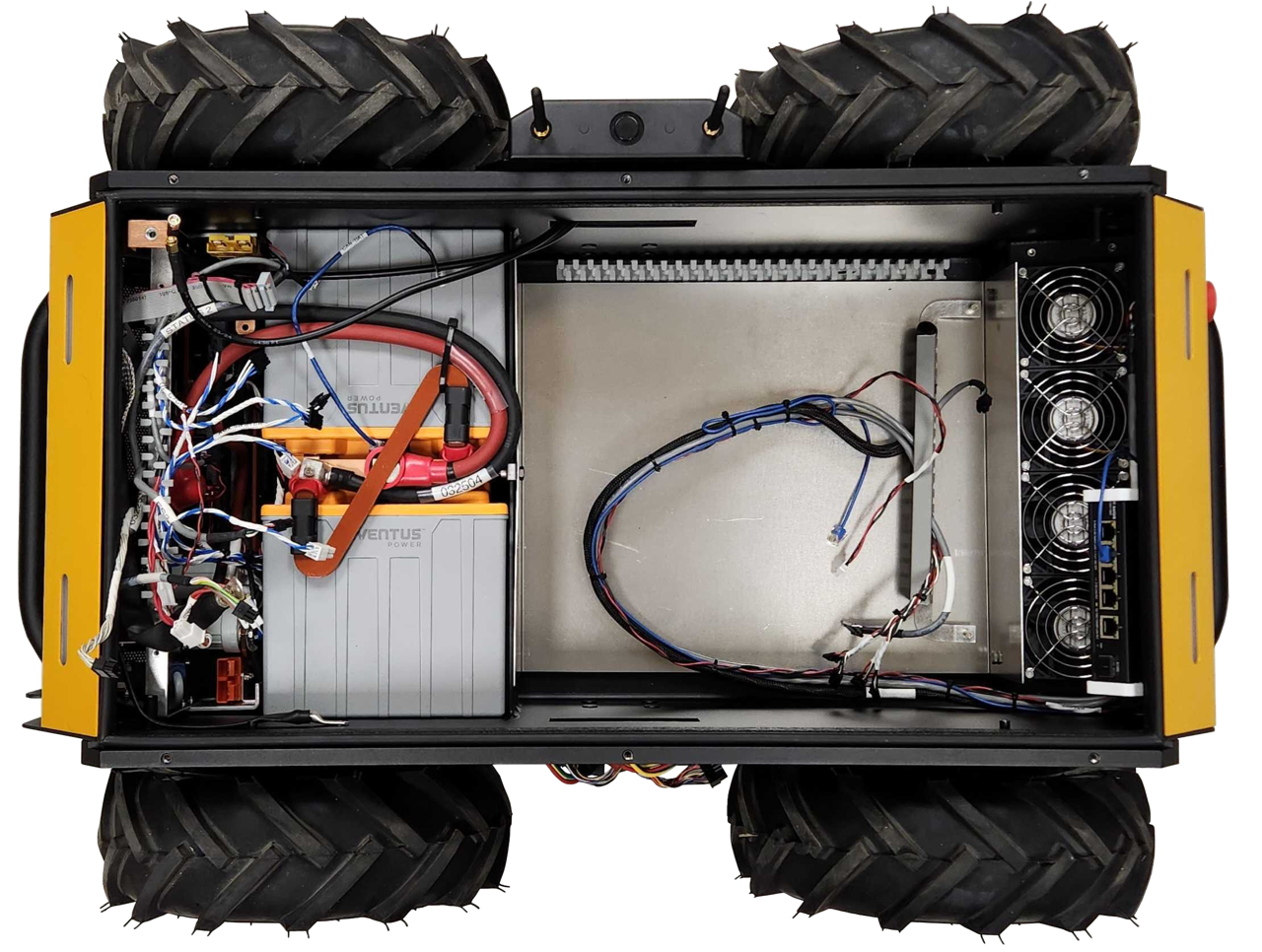
Batteries
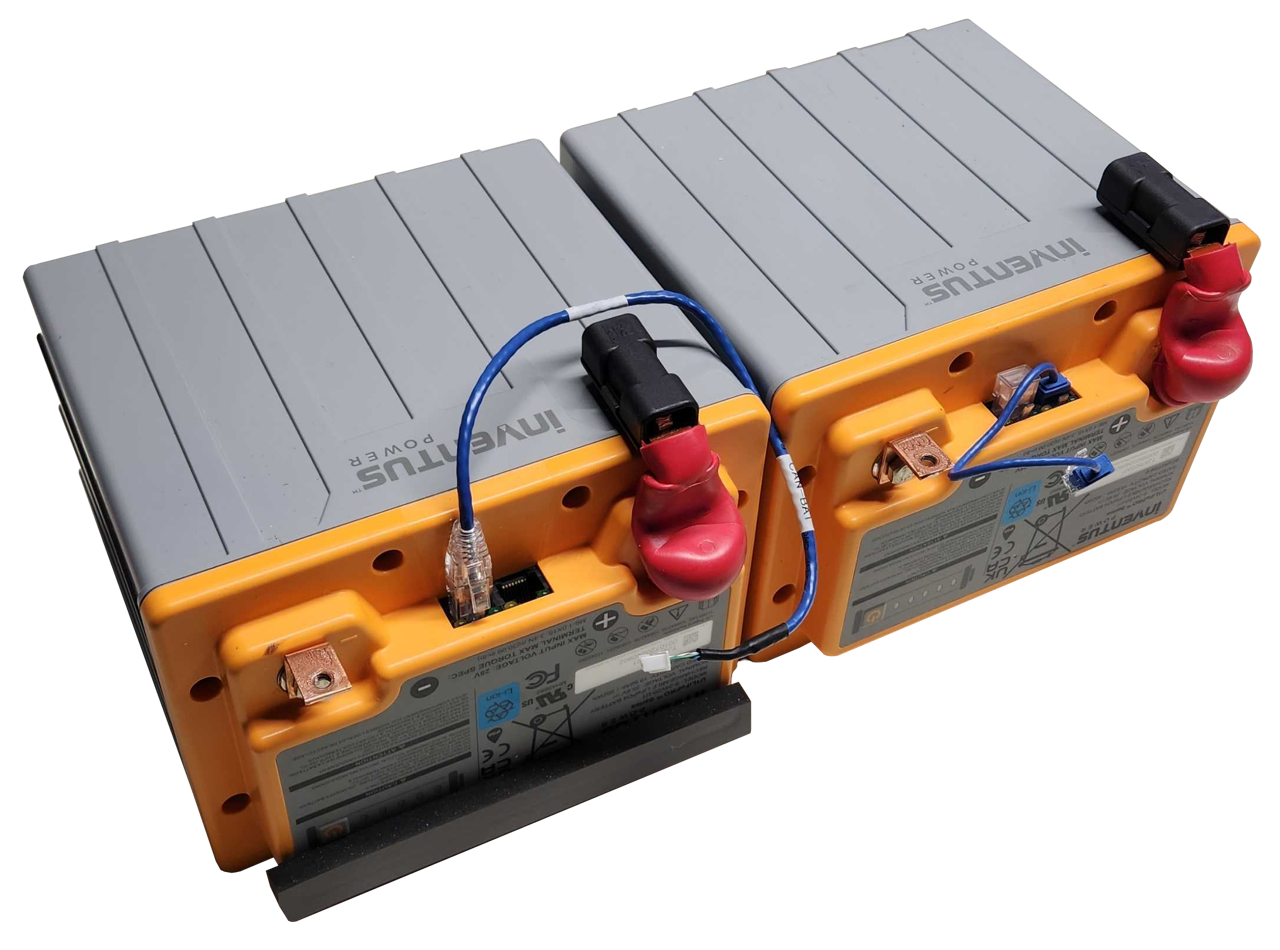
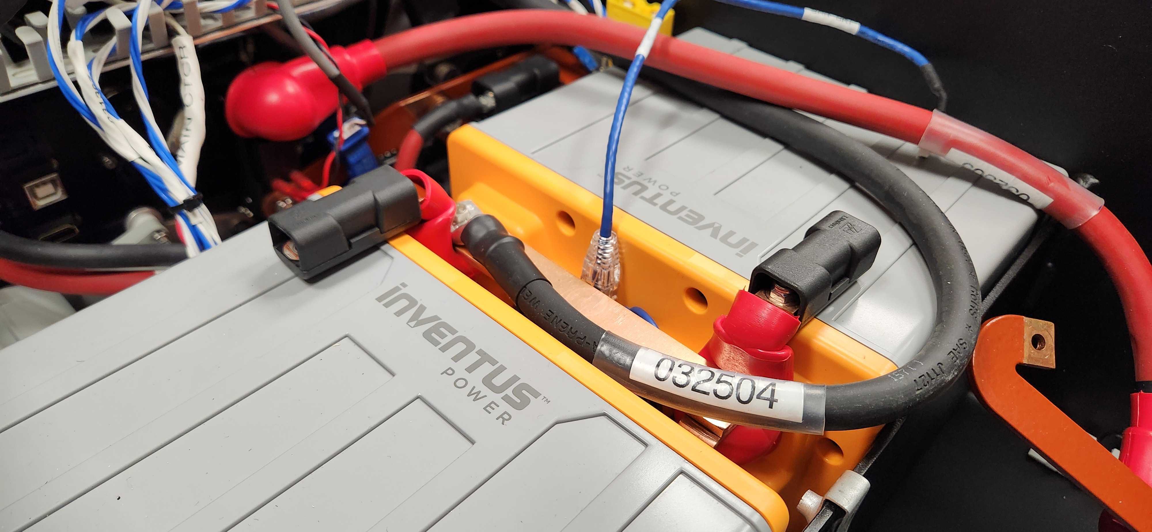
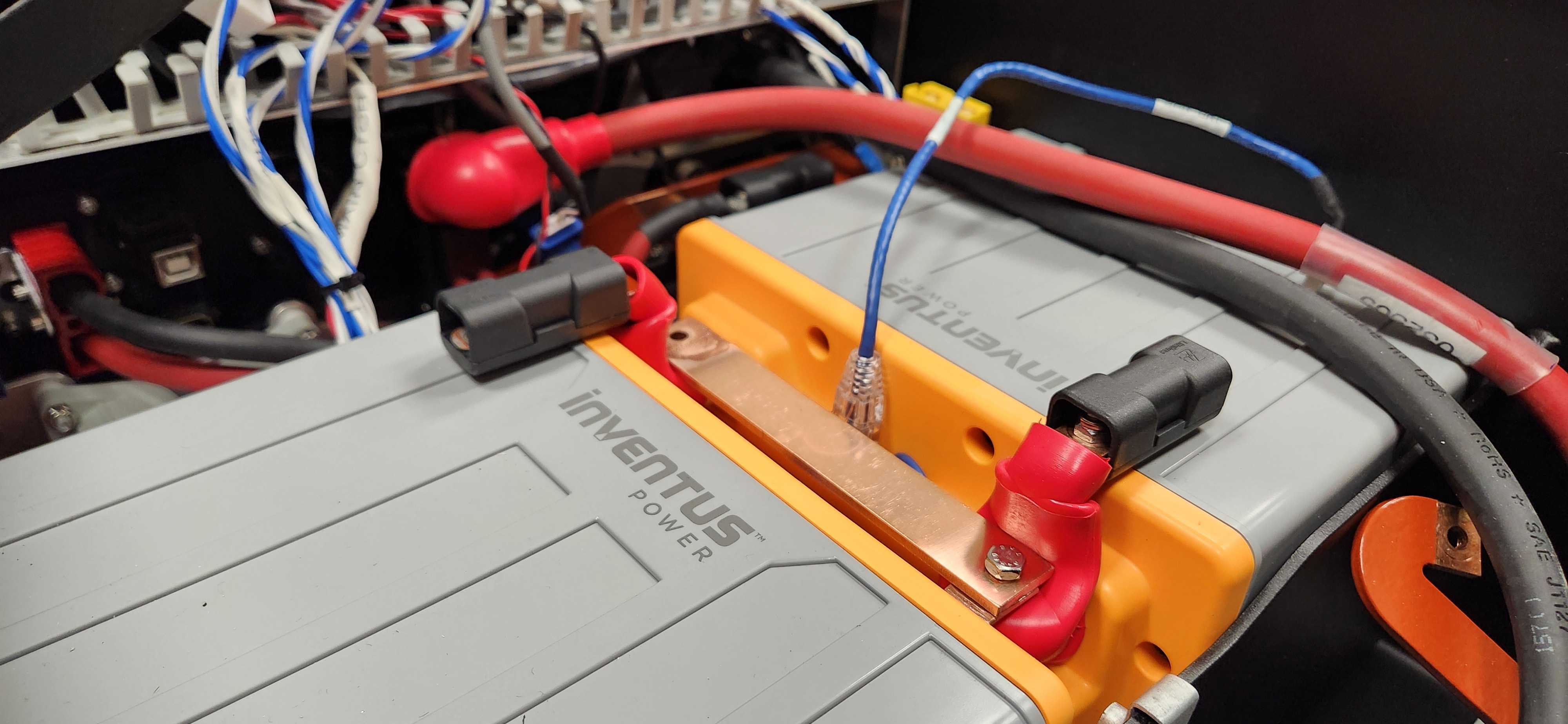
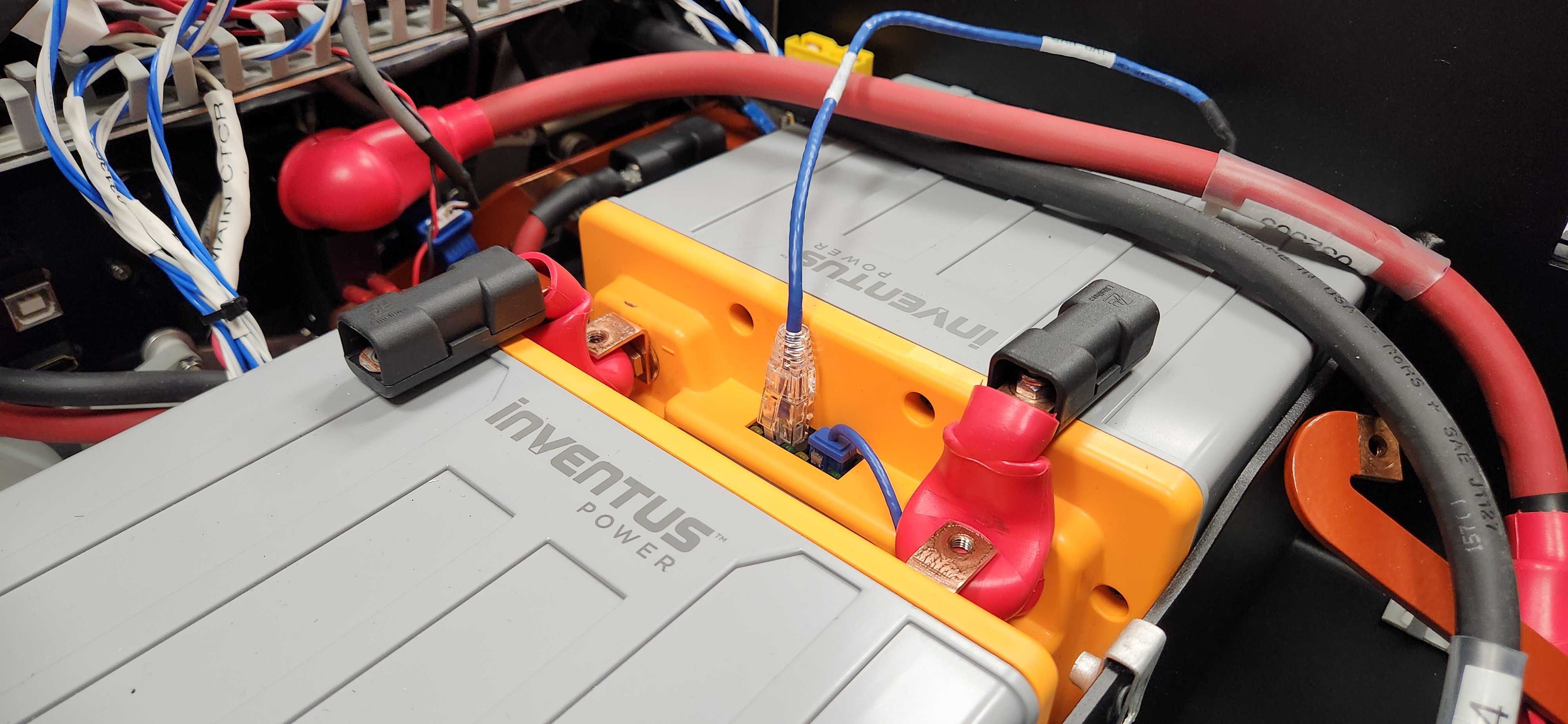
The Husky's batteries are visible once you remove the Electronics Tray. The batteries +V terminals are always live, even when the circuit breaker is in the Off position. You may want to remove the batteries to replace them, or to access the Power Distribution subassembly.
The images show the Husky 40 Ah configuration which has 2 batteries. The 80 Ah and 120 Ah configurations follow a similar process, but with 4 or 6 batteries.
Husky's batteries should last 3000 charge cycles if they are charge balanced at least once per week, and not left in a depleted state.
If you order new batteries from Clearpath Robotics, ask us to configure the batteries for a Husky A300. We will configure the battery software addresses and CAN address before shipping them to you.
To remove the batteries:
-
Remove the Electronics Tray.
-
Loosen the cable comb bracket's 2 screws, and then fold it towards the front of the robot. This will give you better access to the batteries.
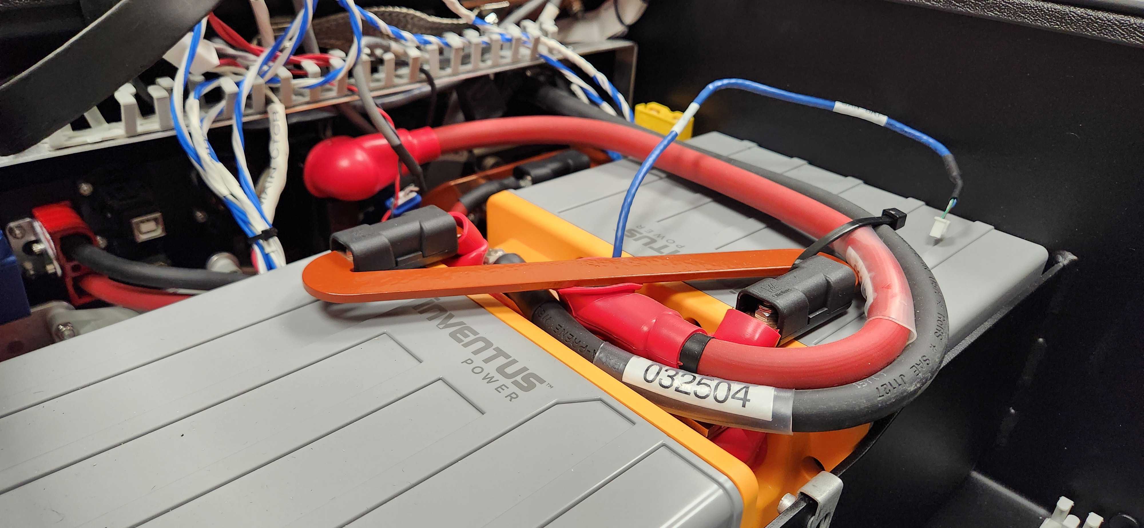
Batteries Are Visible After the Electronics Tray And Cable Comb Have Been Removed -
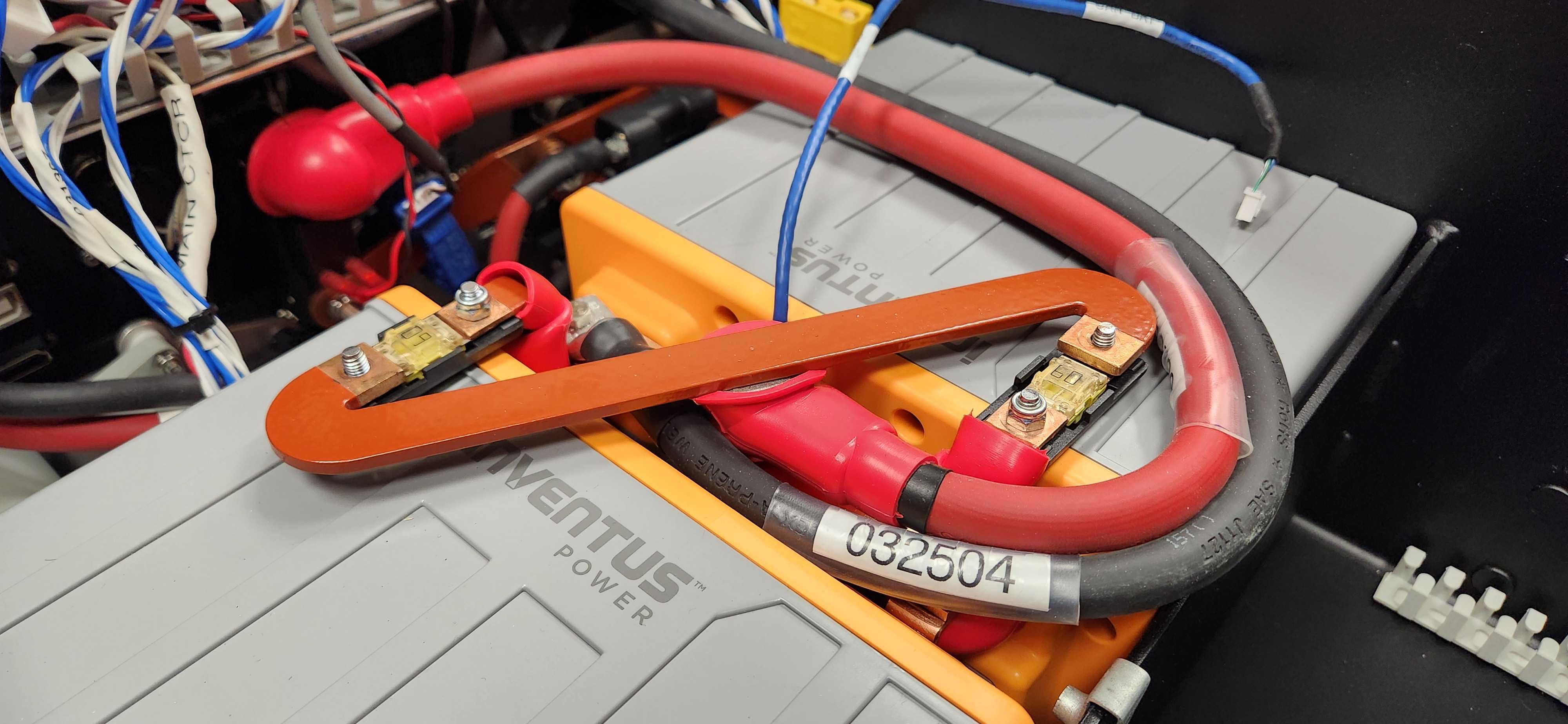
Remove the plastic covers from the fuse holders. These are always live voltage, up to +30 VDC.
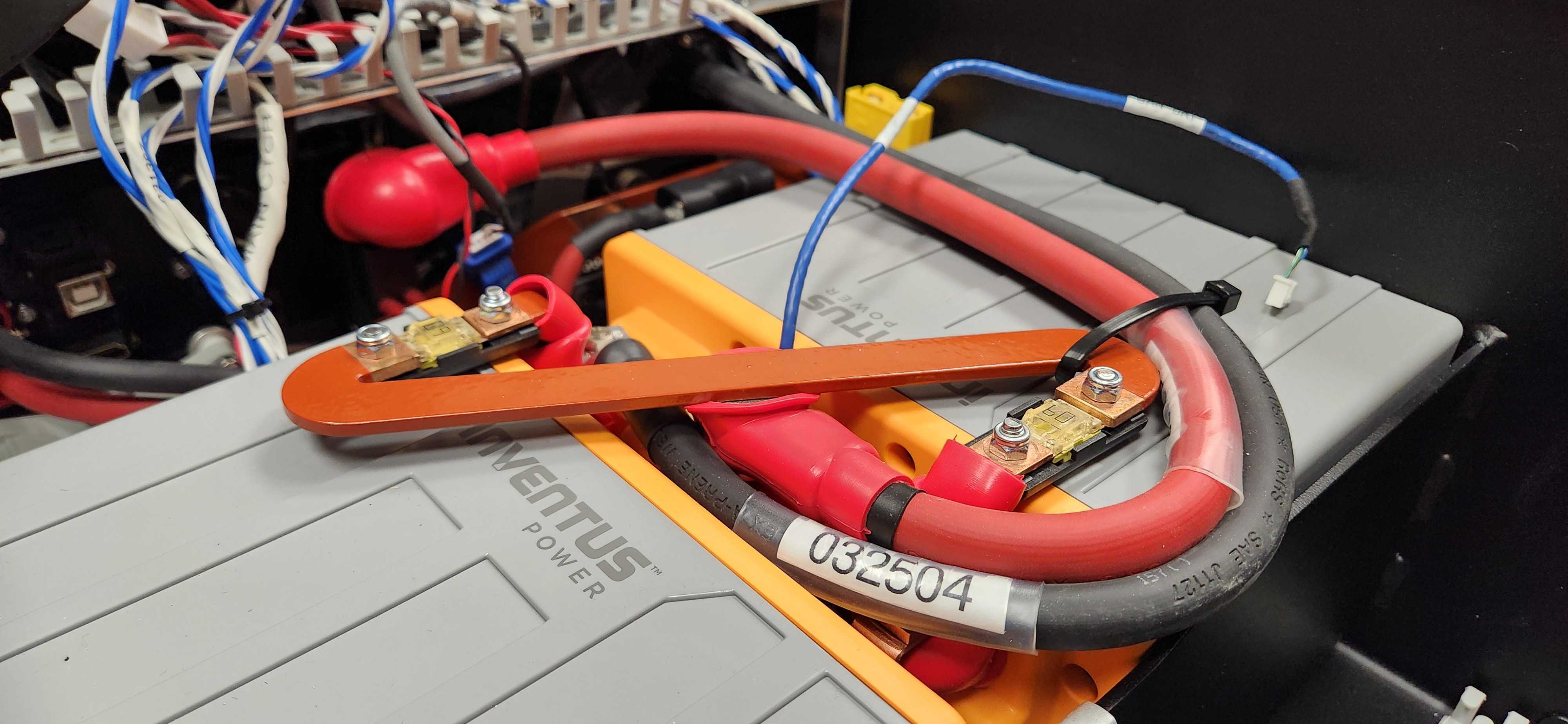
-
Remove the fuse holders's nuts that are holding the red busbar. You may also need to cut a cable tie.
 note
noteWhen reinstalling the busbar:
- Torque the nuts to 3 N·m.
-
Lift the red cable and busbar away from the batteries. The cable will not be live, once it is removed from the fuse holders. The fuses will still be positive voltage.
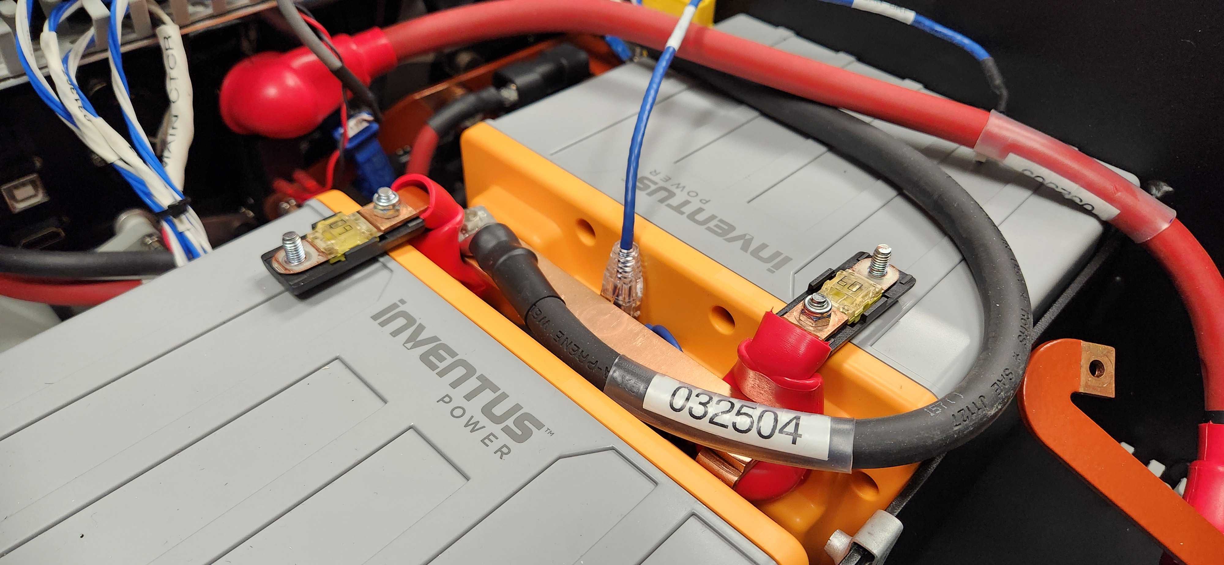
-
Reinstall the fuse holders's covers.
-
Remove the screw and black cable.
 note
noteWhen reinstalling the cable:
- Torque the screw to 5 N·m.
-
Remove the screw and ground busbar.
 note
noteWhen reinstalling the busbar:
- Torque the screw to 5 N·m.
-
Disconnect the Ethernet / CANbus cable.
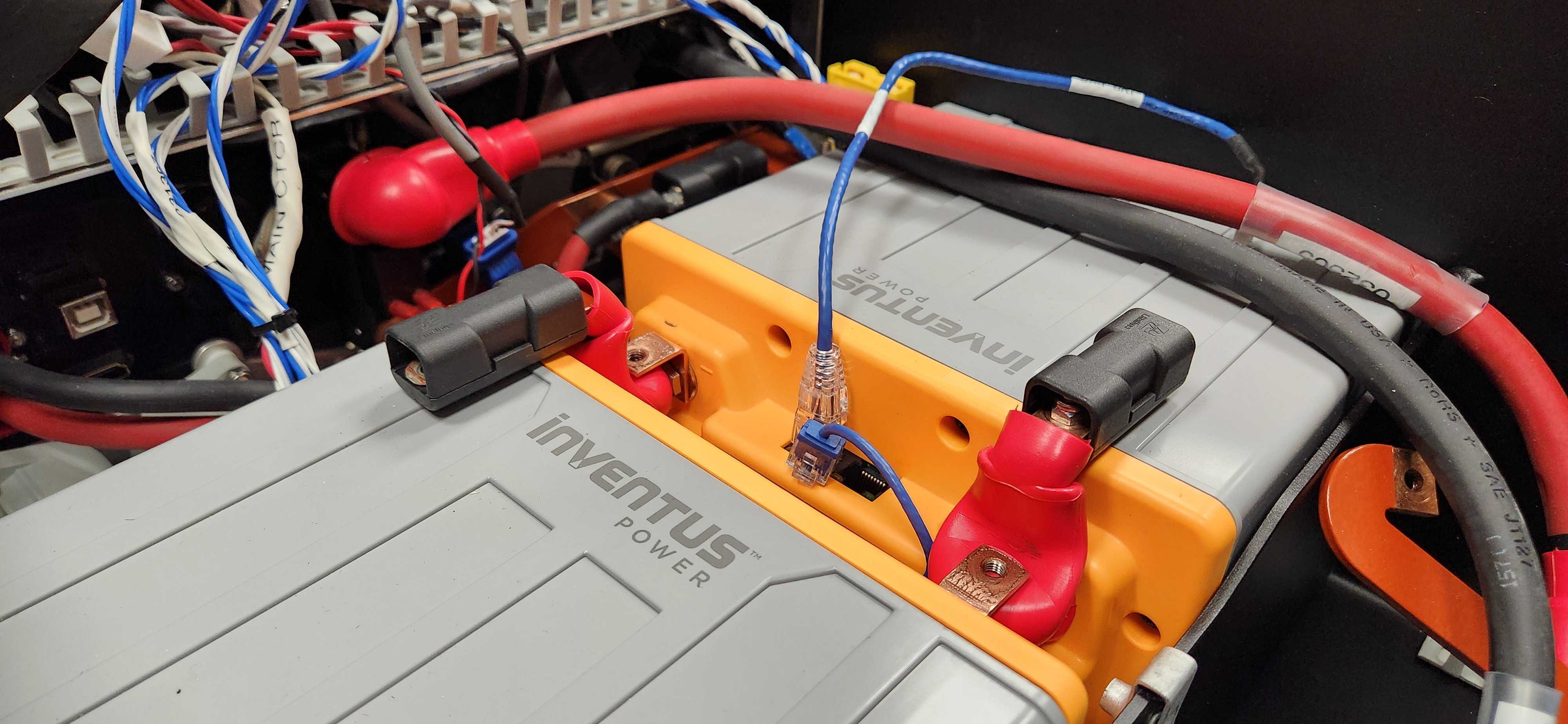
-
Lift the batteries out of the robot.
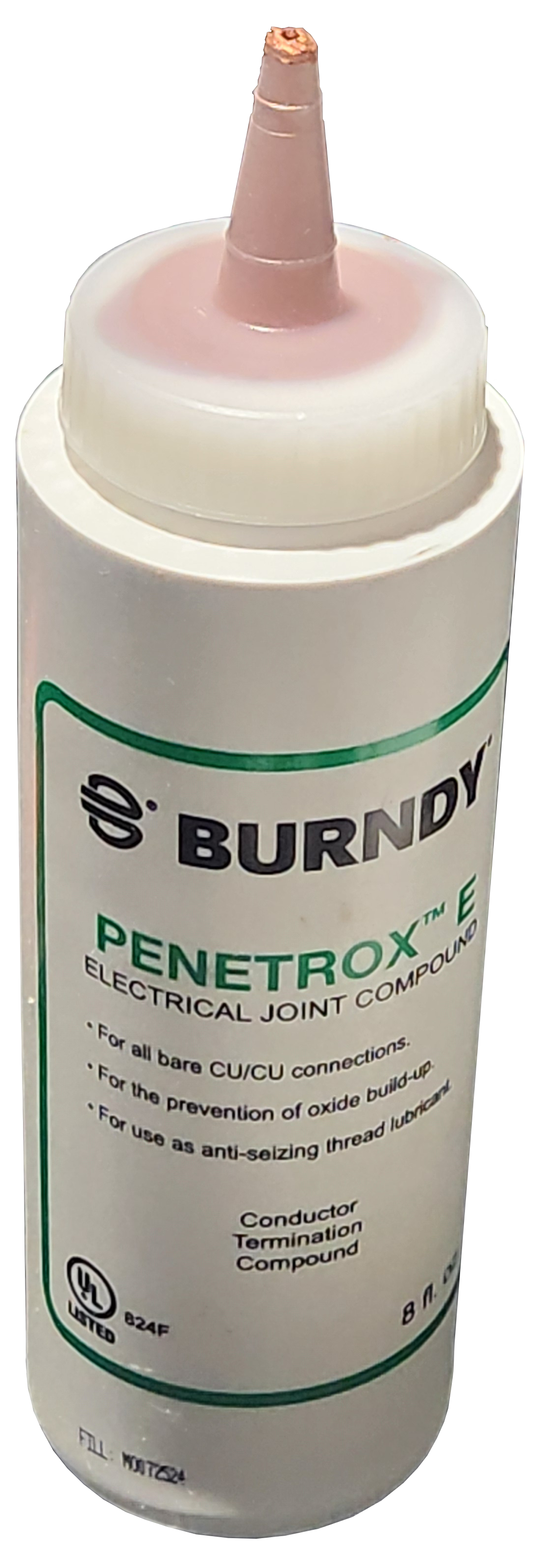
The original Husky A300 builds in 2025 used bare copper busbars. Joints with bare copper surfaces should include Penetrox™ between the mating faces. Excess Penetrox™ can be removed after the joint has been fastened.
Joints with tin-tin contacts do not require Penetrox™.
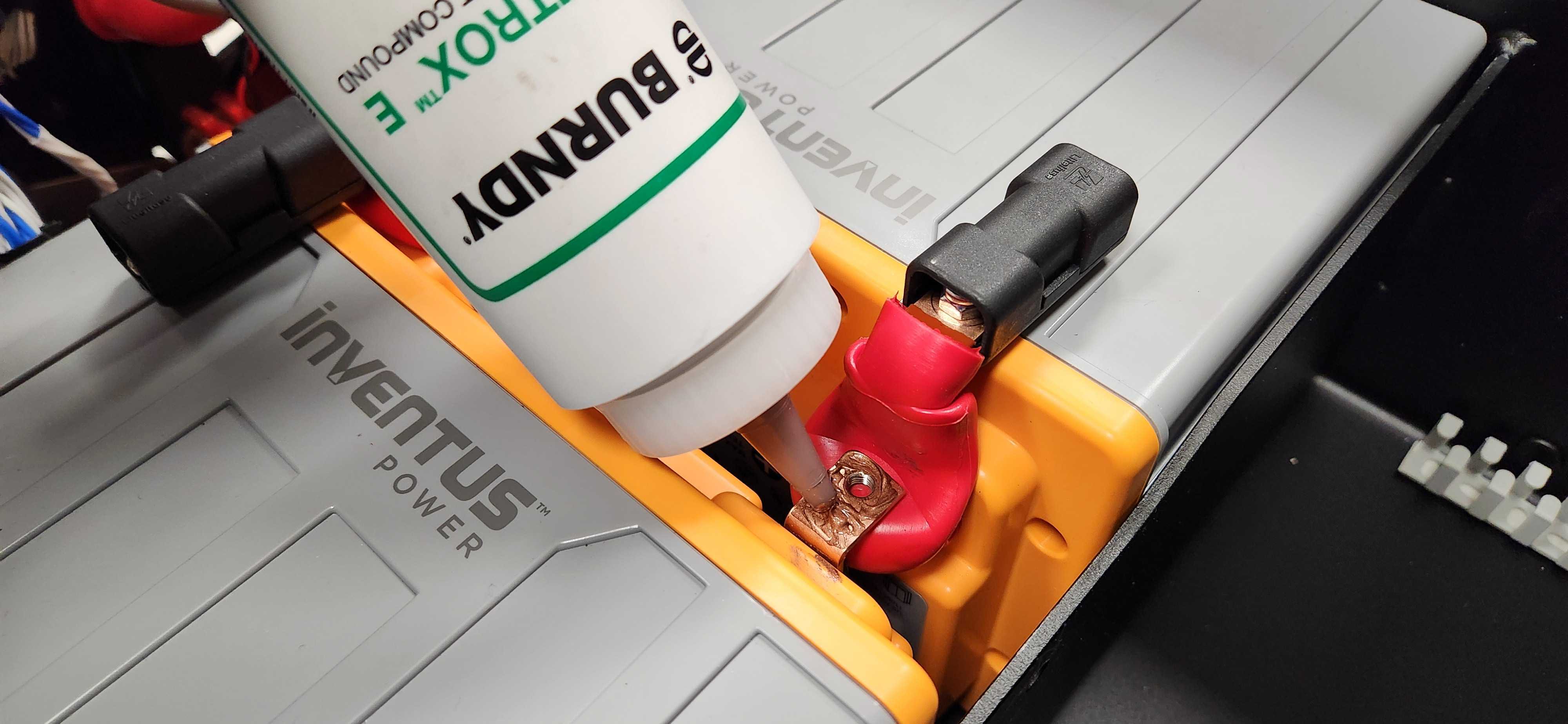
When replacing a battery, only use CPR item 025047 (Inventus S-24V20-U1 battery).
Rear Cover

To remove the Rear Cover
-
Remove the 2 screws and washers.
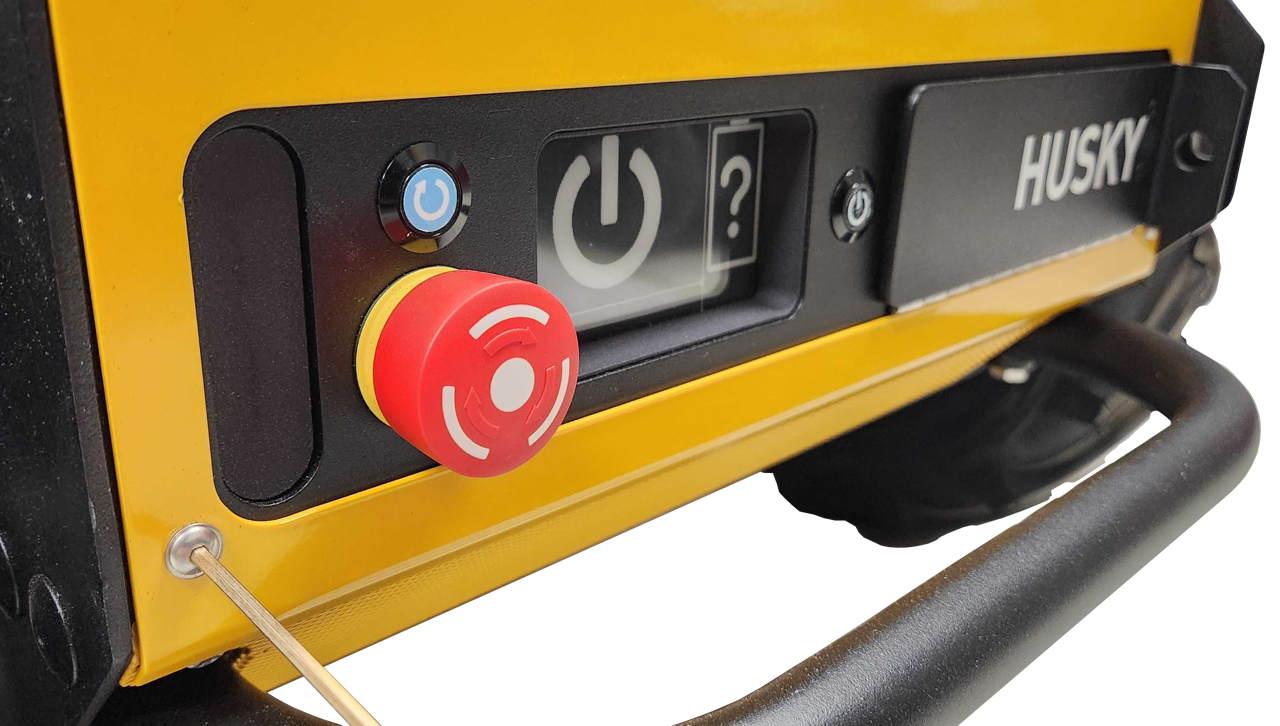
-
Lift the cover's pins from the chassis's 2 rubber grommets. Keep the Rear Charge Port Door closed while removing the Rear Cover.
When reinstalling the cover:
- Make sure the washers are included with the screws.
- Torque the tray's 2 screws to 2 N·m.
Bumpers
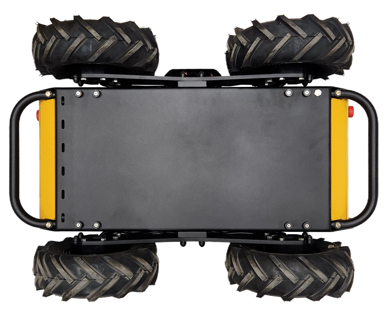
To remove the bumpers:
-
Remove the 2 screws that hold the bumper to the Husky.
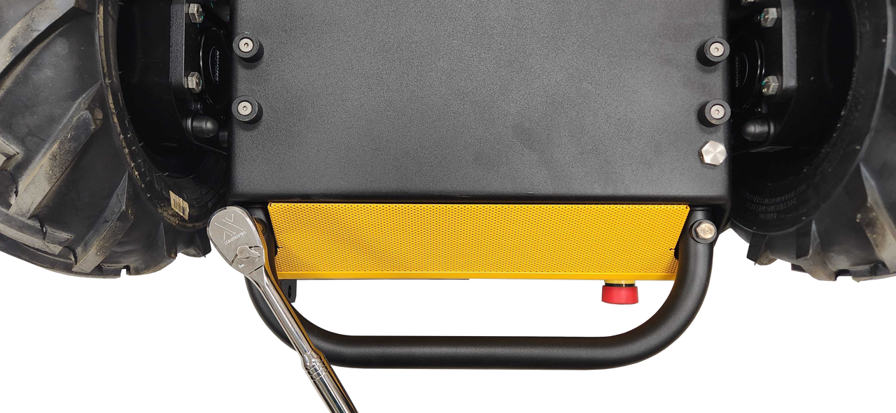
-
Gather the 2 screws, and 4 coped spacers per bumper.
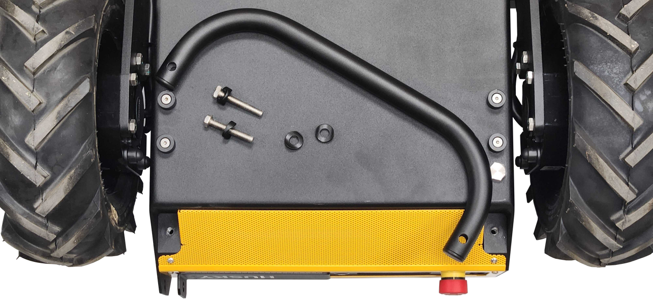
When reinstalling the bumpers:
- Make sure 2 coped spacers are included per screw.
- Torque the screw to 22 N·m.
Air Grilles

The front and rear Air Grilles prevent large debris from entering the robot.
To remove the grilles
- Remove the Bumpers.
- Remove the Front Cover and Rear Cover.
- Remove 2 screws per grille.
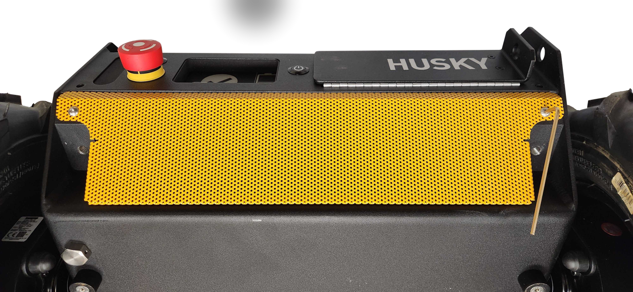
- Remove the grilles.
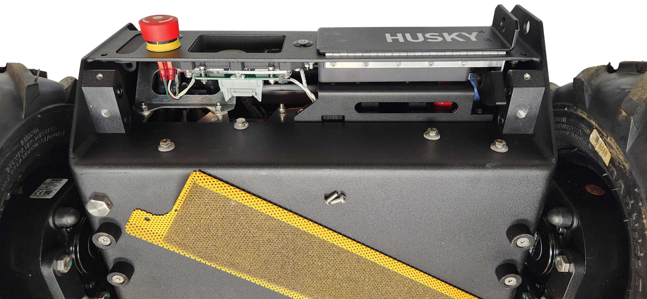
When reinstalling the grilles:
- Make sure to include the thin mesh filter on the Rear Air Grille
- Torque the screws to 2 N·m.
Fans
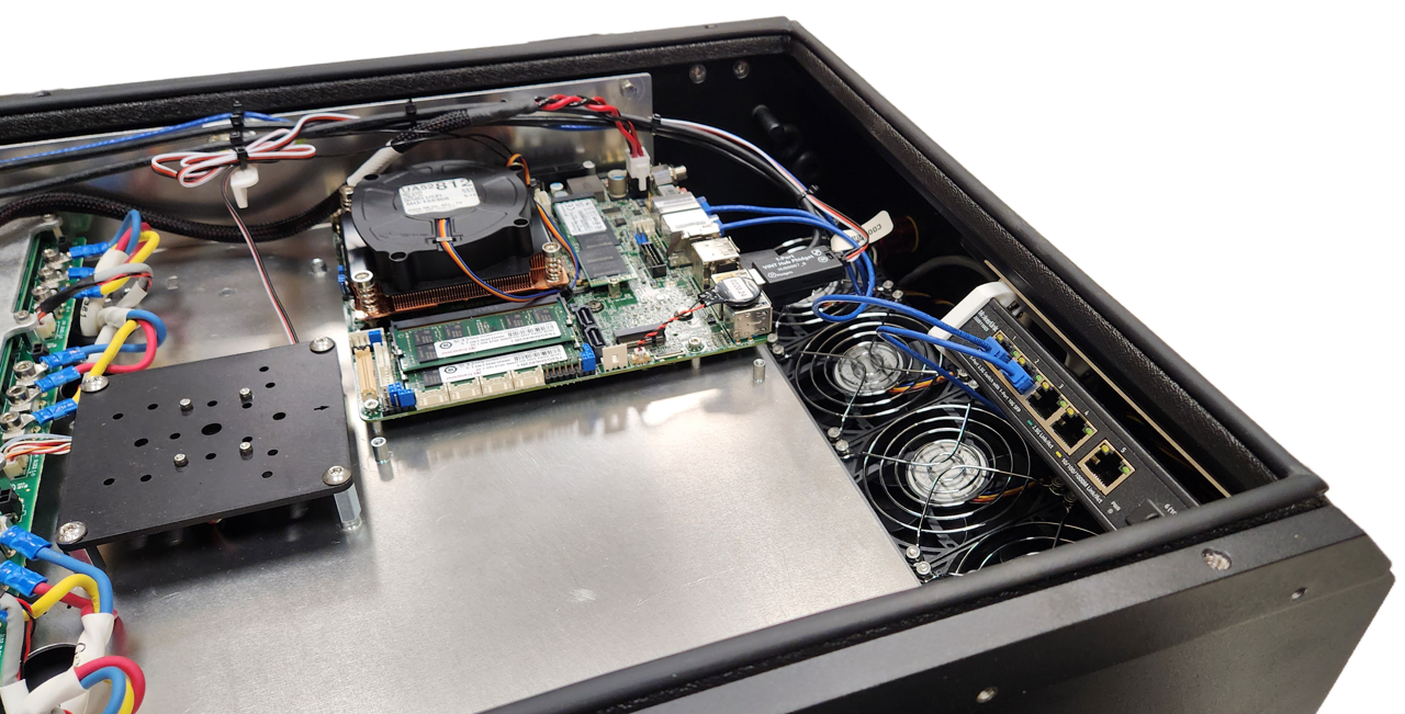
Husky has 4 fans at the front of the robot. These fans operate similar to a server; as all 4 push air into the robot to create positive pressure inside the chassis.
To remove the fans:
- Turn the robot's circuit breaker off.
- Remove the Top Plate.
- Remove the Front Panel and Air Filter.
- Remove the front Bumper.
- Remove the front Air Grille.
- Use a wrench and hex key to remove the 4 fasteners per fan.
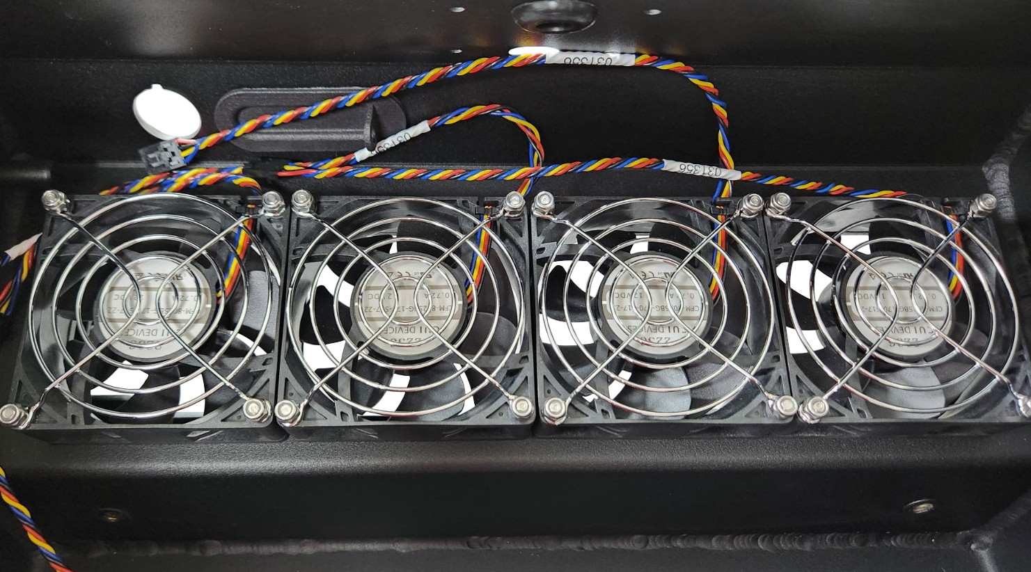
View Inside The Husky's Chassis 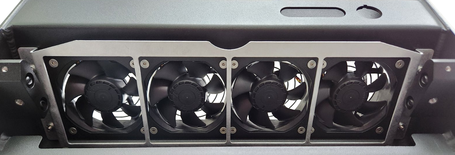
View From The Front Of Husky - Disconnect the fan's latching connector, and remove the fan.
When reinstalling the fans:
- The fan has an arrow on its plastic housing that indicates the airflow direction. Make sure the arrow points into the robot's chassis, to push the air into the robot.
- Fan position 1 is the left / port side of the robot.
- Torque the fans' screws to 2 N·m.
- Make sure to reinstall the Air Filter.
Power Distribution
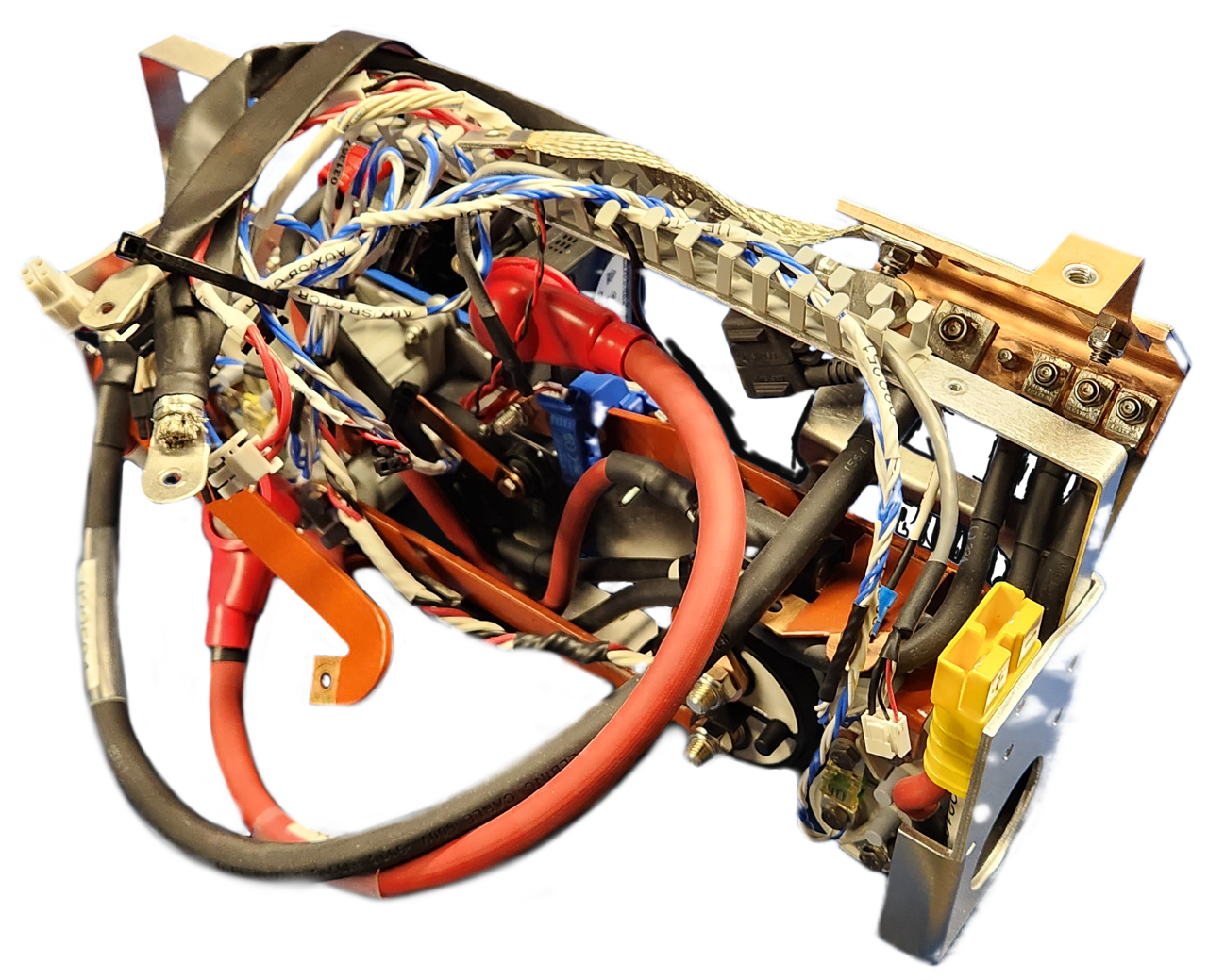
The Power Distribution subassembly includes all the robot's large power electronics:
- Main relay contactor
- Mobility relay contactors
- Shunt brake relay contactors
- Shunt brake resistor
- Large VBAT contactors
- Current sensor
- Circuit breaker
- Fuses
- Busbars, and cables to the batteries
To remove the Power Distribution subassembly:
- Confirm the circuit breaker is in the Off position.
- Remove the Electronics Tray.
- Remove the Rear Bumper, Rear Livery Cover and Rear Air Grille.
- Remove the Power Distribution's 5 screws.
- 1 is above the left Status Light.
- 2 are below the HMI Display.
- 2 are below the Rear Charge Port Door.

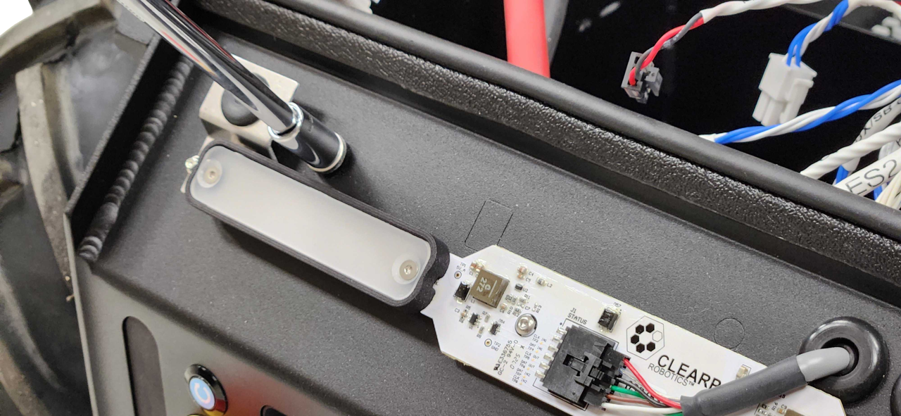
- Remove the nut for the bonding braid.
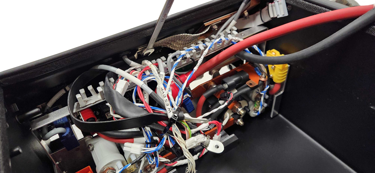
- Pull the Power Distribution assembly forward.
Check that it is not pulling any cables that are still attached to the chassis.
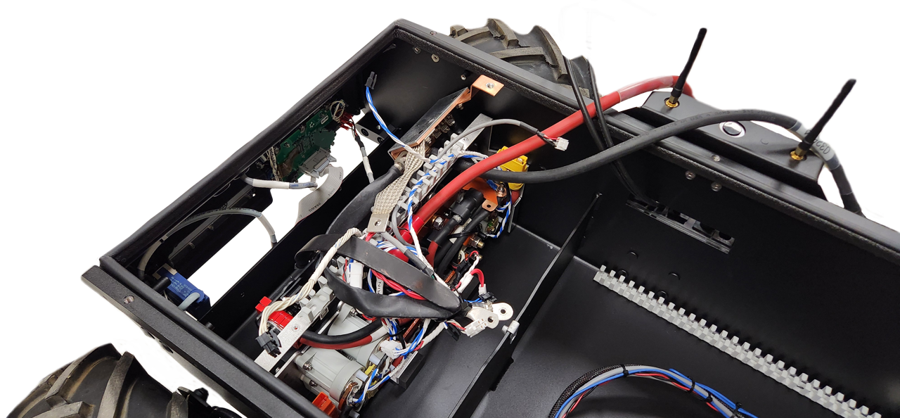
- Remove the Power Distribution from the robot.
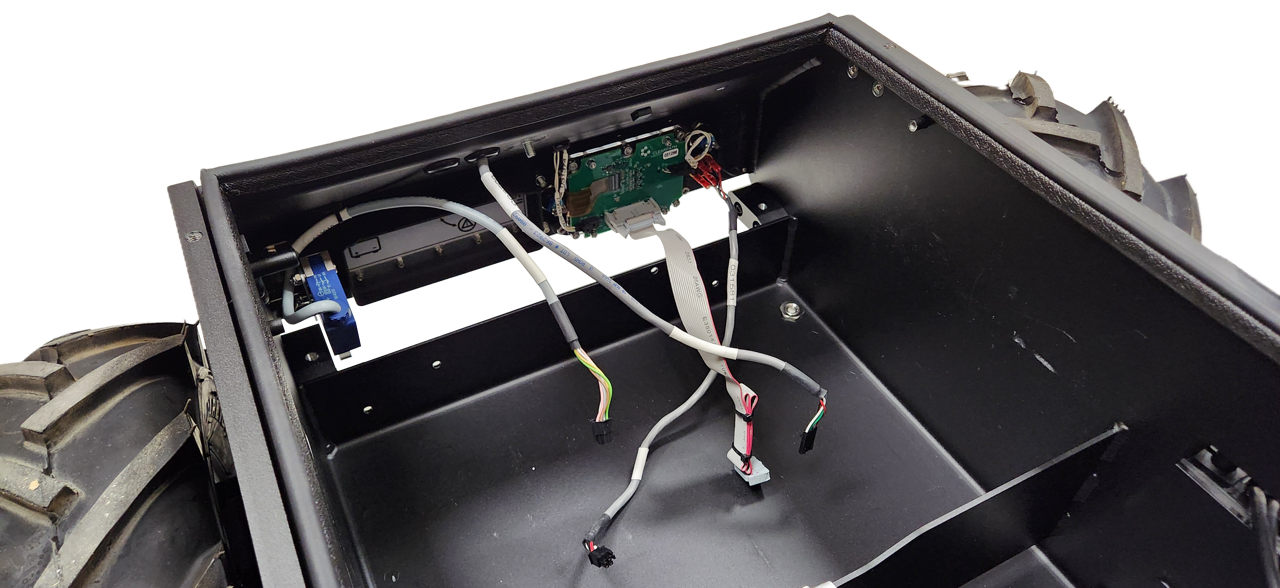
When reinstalling the Power Distribution:
- Make sure the sealing washers are still attached to the screws.
- Add a drop of Loctite 243 thread locker to the threads of the screws before installing them.
- Torque the screws to 1.2 N·m.
- Torque the bond braid's nut to 6 N·m.
Status Lights
To remove the light assemblies:
- Turn the robot's circuit breaker off.
- Remove the Front Panel.
- Remove the Rear Panel.
- Disconnect the light's cable.
- Remove the 2 nuts that fasten the metal brackets to the chassis.
- Remove the light subassemblies from the robot.
When reinstalling the light assembly:
- Torque each light assembly's 2 nuts to 2 N·m.
To remove the PCBA from the assembly:
- Remove the 2 flat head screws from each of the plastic diffusers.
- Remove the diffusers and cowls.
- Remove the PCBA.
When reinstalling the PCBA:
- Torque each of the diffusers's 2 screws to 0.3 N·m.
Network Switch
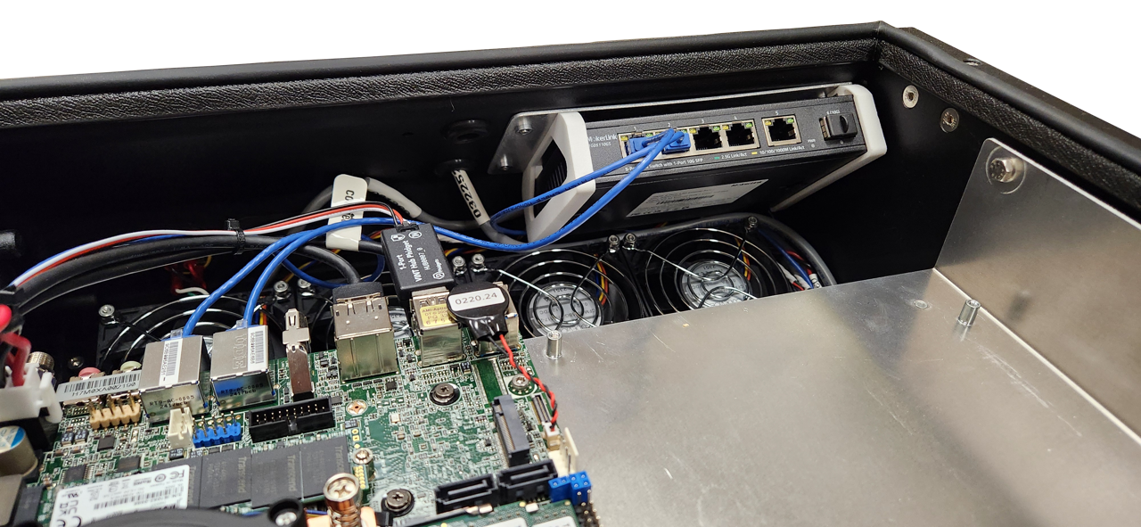
The network switch connects the primary computer, the rear debugging port, and any additional Ethernet devices.
To remove the switch:
- Shut off the robot's circuit breaker.
- Remove Husky's Top Plate.
- Remove any network cables from the switch.
- Remove Husky's Front Panel.
- Remove the 4 screws and waterproofing washers, while holding onto the switch.
- Disconnect the switch's power cable, and remove it from the robot.
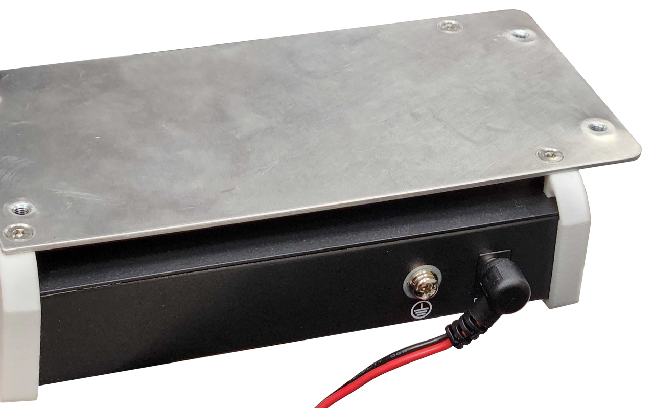
When reinstalling the switch:
- Make sure the power cable is connected.
- Make sure the waterproofing washers are included.
- Torque the 4 screws to 1.2 N·m.
To remove the switch from its subassembly brackets:
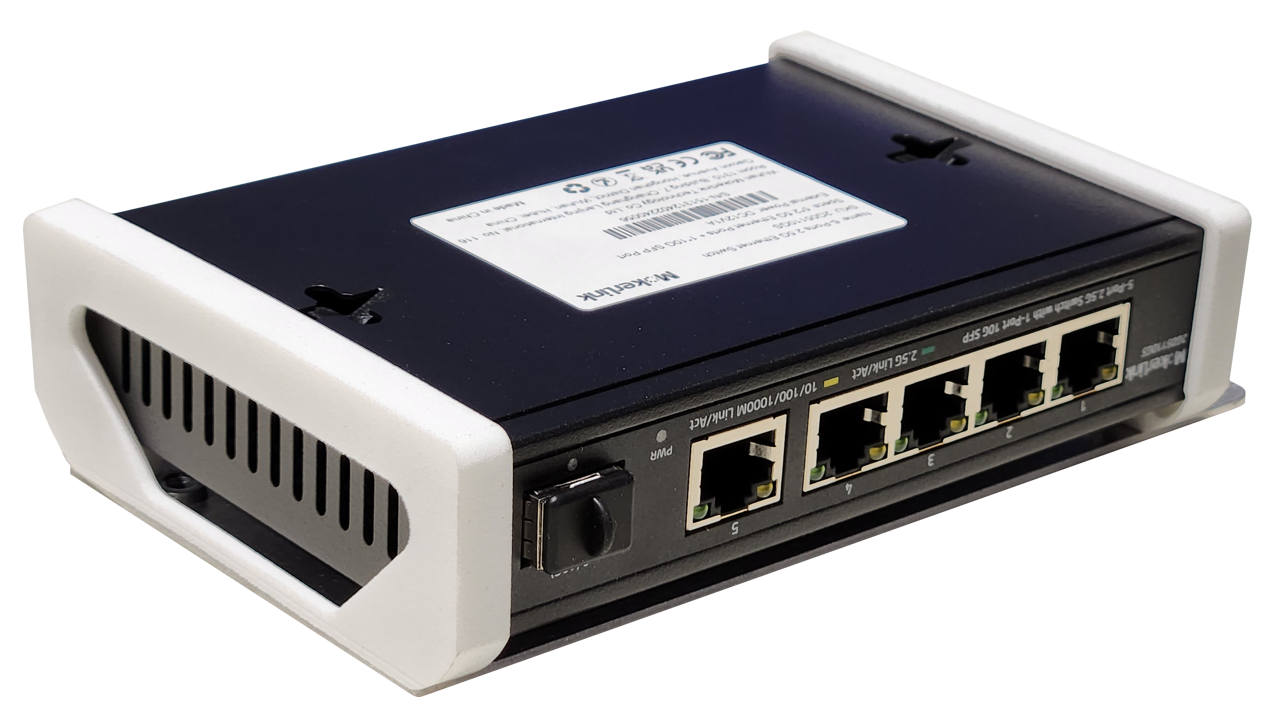
- Remove the 4 flat head screws.
- Remove the switch from the plastic brackets.
When reinstalling the switch:
- Torque the 4 screws to 0.5 N·m.
Computer
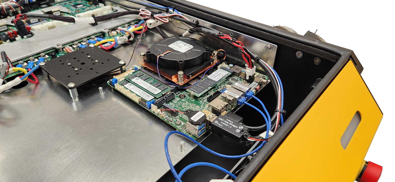
There are 2 computer mounting locations on Husky's Electronics Tray. Both mounting locations are sized for Mini-ITX computers.
Clearpath offers a standard computer with an Intel i3 processor, or a performance option with a i7 processor—though custom builds are also an option.
To remove a computer:
- Turn the robot's circuit breaker off.
- Remove Husky's Top Plate.
- Disconnect any cables from the computer:
- USB.
- Ethernet RJ45.
- HDMI.
- Wi-Fi antennas.
- Power cable.
- Optional graphics card's PCIe riser cable.
- Remove the 4 screws fastening the computer to Husky's Electronics Tray.
- Remove the computer from the robot.
When reinstalling the computer:
- Torque the 4 screws to 1 N·m.
If you are changing the Wi-Fi or Storage M.2 cards:
-
Torque these screws to 0.3 N·m.
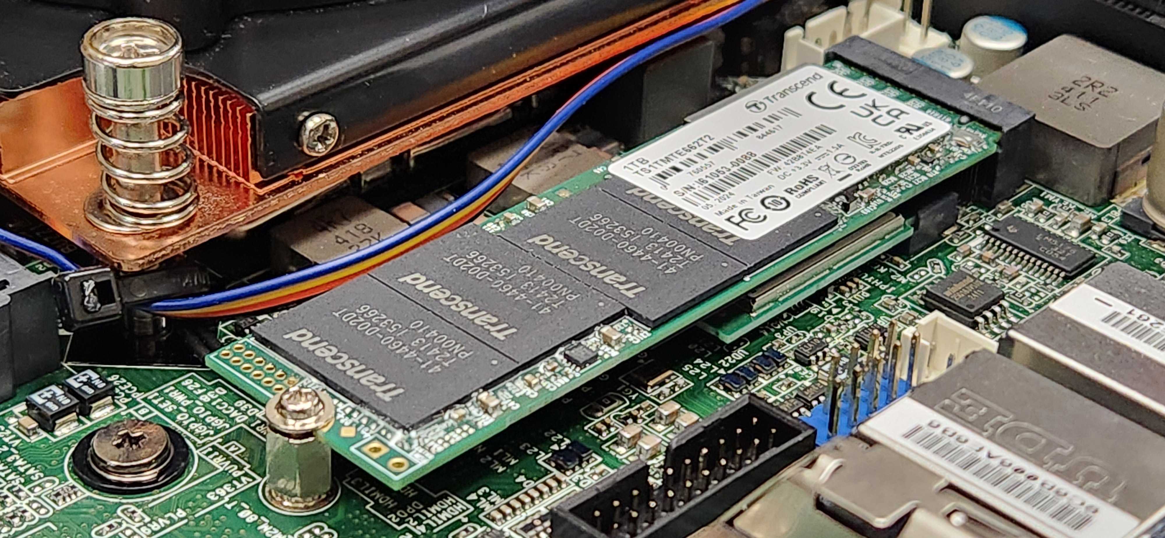
Replacing CMOS Battery
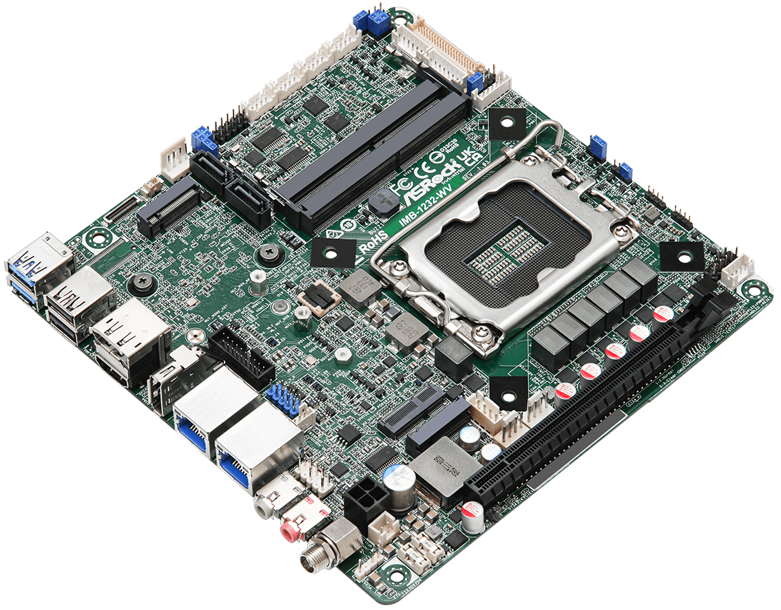
These instructions were developed in 2026 for our robots' mini-ITX computer with a 13th gen intel processor.
Our computers include a CMOS battery to maintain configuration settings while the robot is off. The CMOS battery will recharge whenever the robot is running. The battery typically needs to be replaced after 1 - 2 years.
A common symptom of a depleted CMOS battery is the computer not turning on. Your robot's microcontroller may turn on, so lights and fans may run; but the robot will not drive.
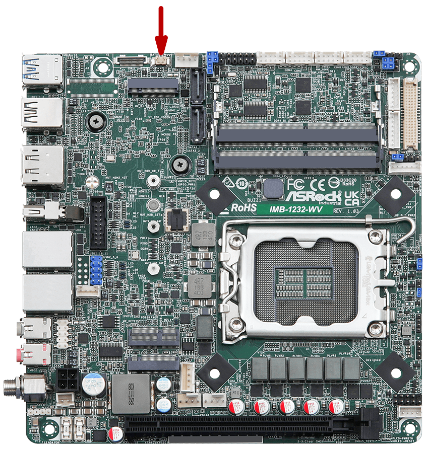
To change the battery:
- Confirm that your robot includes an ASRock Industrial IMB-1232-WV motherboard. Other computer models will include a CMOS battery, but the battery pinout and connector location will be different.
- Get a replacement battery, Clearpath Robotics item 033060.
- Confirm that the replacement battery has the same pinout as the battery you are removing from the robot's computer.
- Remove the old battery.
- Install the new battery, attaching the electrical connector, and mounting the battery with its peel-and-stick pad.
You will need to update the computer's BIOS settings after replacing the battery.
Debugging The System Interface Assembly, (Debug LEDs)
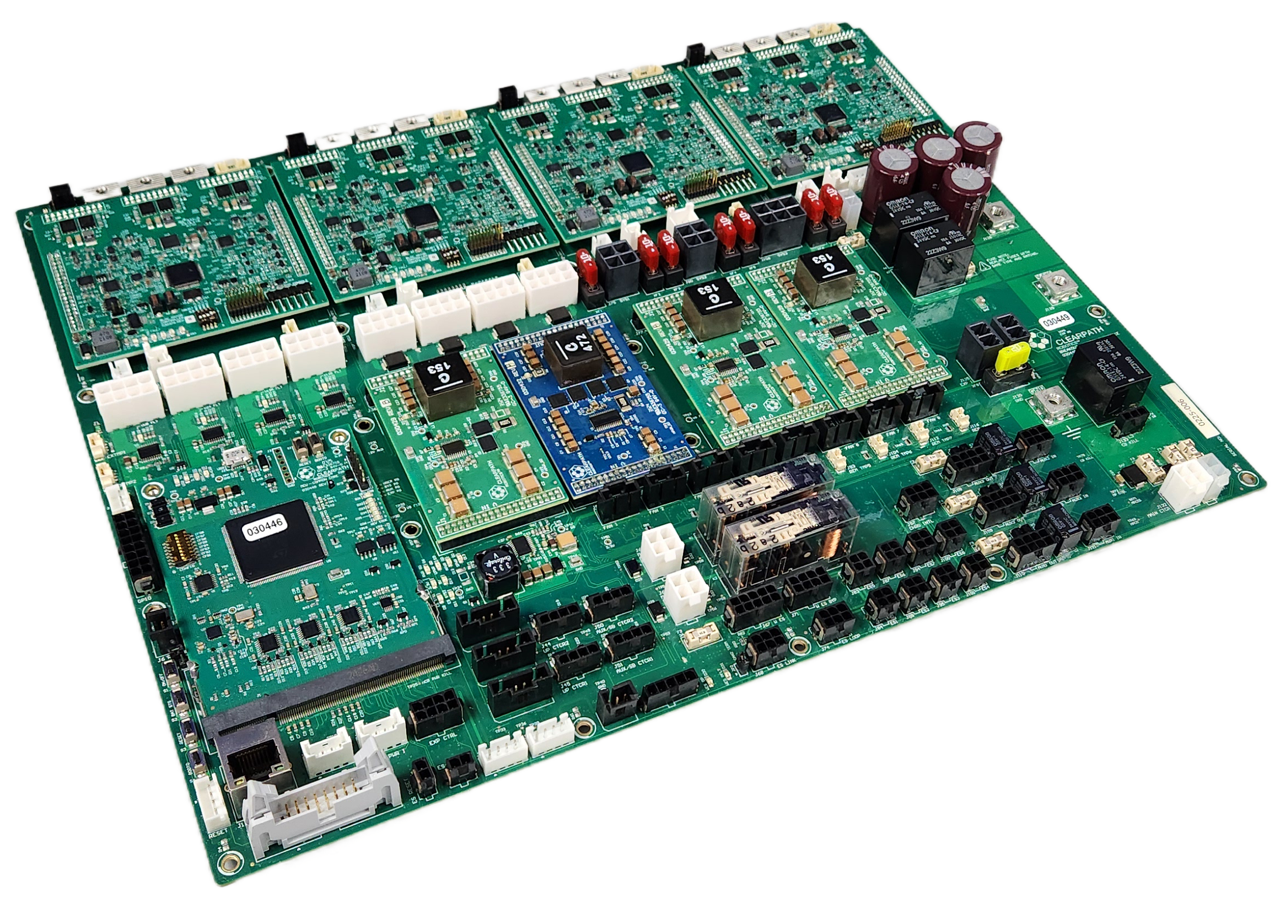
The System Interface Assembly includes many LEDs to help debug system issues.
WARNING
The Husky must be powered on, with the Top Plate removed to see these Debug LEDs. This exposes significant battery energy to the technician, and risk of starting a fire.
Review your worksite's safe operating procedures before performing this task.
Click to see all the LED functions
Common Core Debug LEDs
D6: USB 5V: Solid green if a USB cable is plugged in and used to power the boardD7: 3.3V: Solid green when the 3.3 V power rail is operational; else offD9: DBG/CON: For future useD11: HB/ERR: Heartbeat that toggles (red/off) every 500 ms when the main firmware loop is running; solid on or off indicates an error
DC/DC Debug LEDs
D3: V OUT: Solid green when the output is operational; else off
Motor Controller LEDs
5V0: Solid green when the 5 V power rail is operational; else off3V3: Solid green when the 3.3 V power rail is operational; else offMTR_FAULT: Solid red when a motor fault is detected; else offERROR: Toggles (red/off) every 500 ms when a motor control error is detected; else offDBG2: For future useDBG1: Heartbeat that toggles (green/off) every 500 ms when the firmware loop is running; solid on or off indicates an error
Main Circuit Board Debug LEDs
D2: UVB FLT: User power VBAT fault: red if the user battery rail is not enabled or if there has been a fault such as an overcurrent or over temperature event; else offD3: U24 FLT: User power 24V fault: red if the user 24V rail is not enabled or if there has been a fault such as an overcurrent or over temperature event; else offD4: U12A FLT: User power 12VA fault: red if the user 12VA rail is not enabled or if there has been a fault such as an overcurrent or over temperature event; else offD5: U12B FLT: User power 12VB fault: red if the user 12VB rail is not enabled or if there has been a fault such as an overcurrent or over temperature event; else offD6: PWR GD: Main power good indicator: red if any power supply is not enabled or has a fault; else offD7: 3.3V: Solid green if 3.3V rail is operational; else offD9: UPWR GD: User power good indicator: red if any of the 4 user power rails are not enabled or have a fault (including and overcurrent on any channel); else offD10: 5V: Solid green if 5V rail is operational; else offD12: APWR GD: Auxiliary power good indicator: red if either of the auxiliary power supplies are not enabled or has a fault (Auxiliary power supplies the USER power as well as other PCBA subsystem power rails at 12V and 24V); else offD13: SPWR GD: System power good indicator: red if either of the system power supplies are not enabled or has a fault (System power supplies the power for PCs, any optional GPU, and the primary network switch); else offD30: WES BP: Wireless E-Stop Bypass indicator: green if the Wireless E-Stop Bypass is enabled; else offD31: WES PFLT: Wireless E-Stop Power fault: red if the power supply is not enabled or has a fault; else offD46: XPWR GD: Expansion power good indicator: red if expansion power is not enabled or has a fault; else off
Replacing Circuit Boards
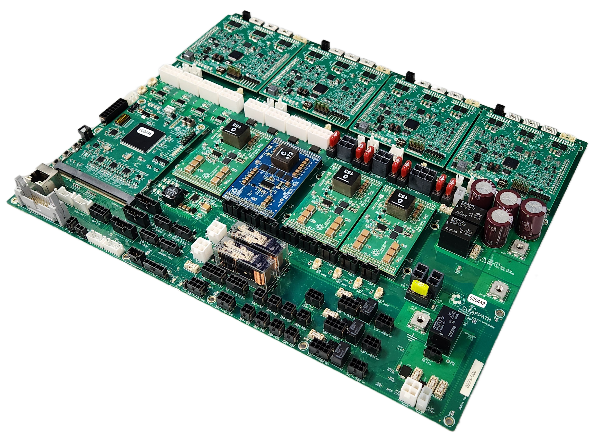
Husky has several circuit boards—(PCBAs). It is uncommon for a PCBA to fail during operation, but could occur from physical damage during a maintenance task. If a failure occurs, usually only one board needs to be replaced, rather than the full System Interface Assembly.
PCBAs are sensitive components and can be damaged easily through electrostatic discharge—(ESD). Be sure to follow proper ESD protection measures prior to handling any circuit boards.
WARNING
Confirm that Husky's Emergency Stop System is functioning after changing any of the circuit boards.
Procedure for replacing the DC-DC and BLDC circuit boards
-
Turn off the robot's circuit breaker.
-
Remove the 7 screws that fasten the Top Plate to the chassis and remove the Top Plate.
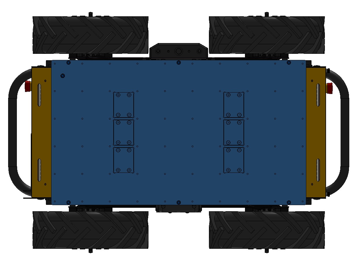
-
Remove the cable brush holder.

-
Remove the heat shield covering the DC-DC or BLDC circuit boards.
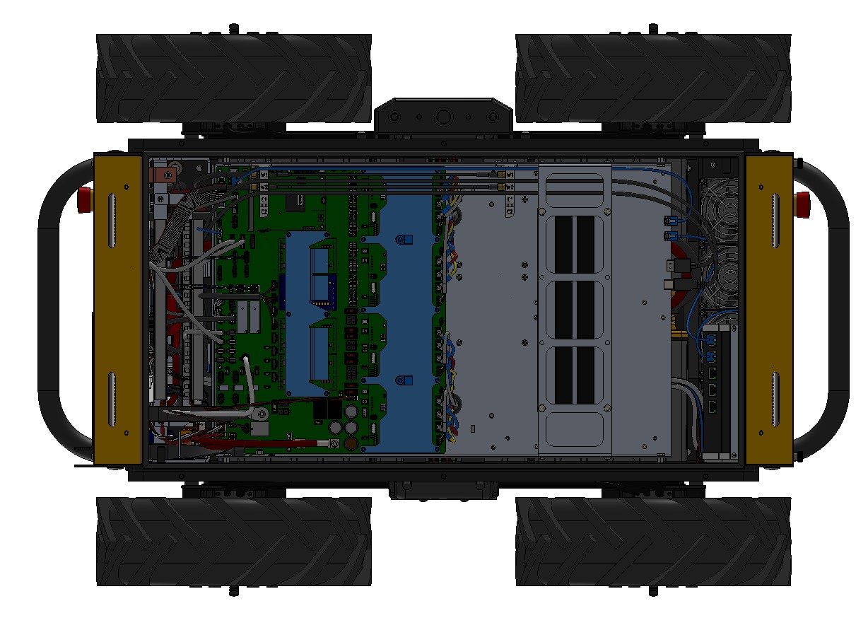
-
Remove the failing circuit board by gently lifting the board up. These circuit boards have many pins, so a large amount of force is required.
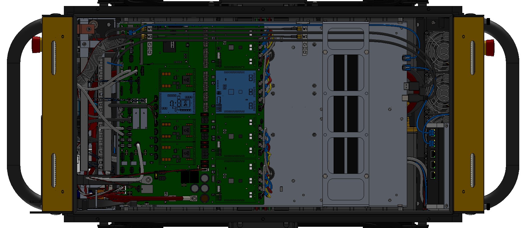
-
Install the new circuit board by aligning the connector and gently sliding it into place.
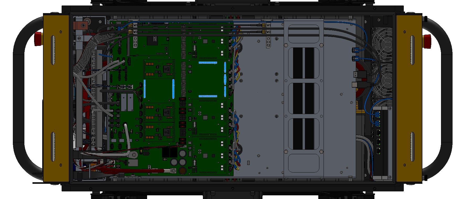
-
Reinstall the heat shields.
-
Reinstall the cable brush holder.
-
Put the Top Plate back in place and finger tighten the 7 screws. Note that the screw with the sealing washer goes in the inner location, and the remaining 6 screws are installed around the perimeter. Tighten all screws to 3 N·m.
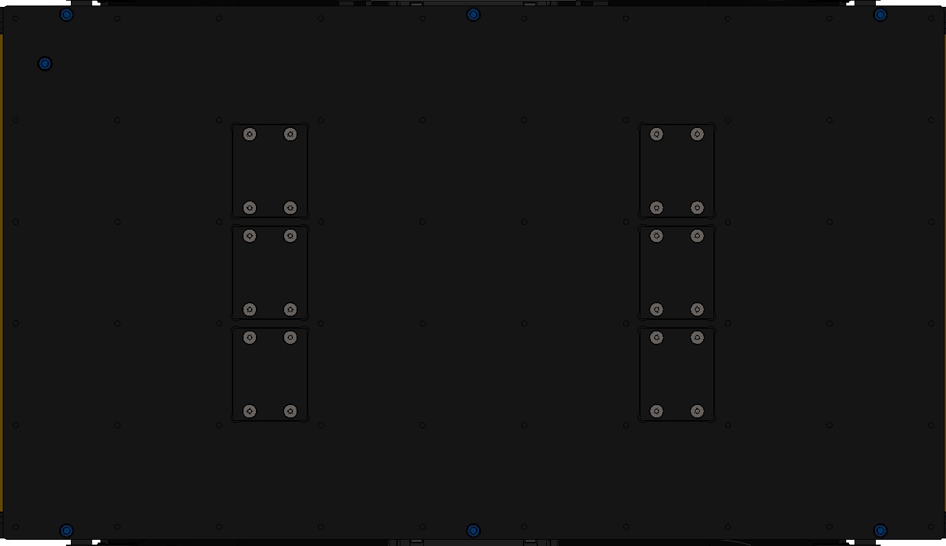
Procedure for replacing the Common Core circuit board
-
Turn off the robot's circuit breaker.
-
Remove the 7 screws that fasten the Top Plate to the chassis and remove the Top Plate.
-
Remove the Common Core by removing the 2 retaining screws, pushing out on the retaining clips, and then gently pulling the board out horizontally.
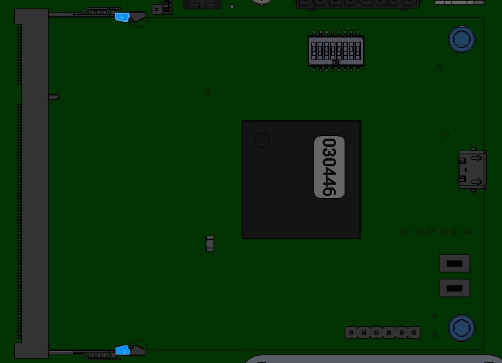
-
Install the new circuit board by gently sliding it into place horizontally, ensure that the retaining clips are secured, and that the two screws have been installed.
-
Put the Top Plate back in place and finger tighten the 7 screws. Note that the screw with the sealing washer goes in the inner location, and the remaining 6 screws are installed around the perimeter. Tighten all screws to 3 N·m.
Procedure for replacing the Main circuit board
-
Turn off the robot's circuit breaker.
-
Remove the 7 screws that fasten the Top Plate to the chassis and remove the Top Plate.
-
Disconnect all cables from the Main circuit board.
-
Remove the Main circuit board by removing the screws and then lifting out the board.
-
Place the old and new Main circuit boards on an ESD mat.
-
Move the functional DC-DC, BLDC, and Common Core circuit boards from the old Main circuit board to the new Main circuit board by following the procedures above.
-
Install the new Main circuit board tighten the retaining screws to 1 N·m.
-
Reconnect all cables, noting that the labels on the cables should match those on the board.
-
Put the Top Plate back in place and finger tighten the 7 screws. Note that the screw with the sealing washer goes in the inner location, and the remaining 6 screws are installed around the perimeter. Tighten all screws to 3 N·m.
Replacing Board Mount Fuses
- Perform the Lockout-Tagout Procedure.
- Locate the fuse to be replaced. Follow the maintenance procedures for the corresponding
subassembly to access the fuse.

CAUTION
Treat all circuits, cables, and fuses inside the robot as potentially live.
Some connections inside the robot are live even after Lockout Tagout. Refer to the details of the subassembly maintenance procedures to determine if the fuse is connected to a live connection. - Use tweezers to pull up on the old fuse to remove it from the fuse holder.
- Slide the replacement fuse into the fuse holder and push firmly until the fuse is installed fully.
note
Ensure that you are replacing the fuse with the same part number and rating. Refer to Common Replacement Items for a list of fuses.
Replacing Mini Blade Fuses
- Perform the Lockout-Tagout Procedure.
- Locate the fuse to be replaced. Follow the maintenance procedures for the corresponding
subassembly to access the fuse.
CAUTION
Treat all circuits, cables, and fuses inside the robot as potentially live.
Some connections inside the robot are live even after Lockout Tagout. Refer to the details of the subassembly maintenance procedures to determine if the fuse is connected to a live connection. - Pull up on the old fuse to remove it from the fuse holder.
- Slide the replacement fuse into the fuse holder and push firmly until the fuse is installed fully.
note
Ensure that you are replacing the fuse with the same part number and rating. Refer to Common Replacement Items for a list of fuses.
Replacing BF1 Fuses
- Perform the Lockout-Tagout Procedure.
- Locate the fuse to be replaced. Follow the maintenance procedures for the corresponding
subassembly to access the fuse.
CAUTION
Treat all circuits, cables, and fuses inside the robot as potentially live.
Some connections inside the robot are live even after Lockout Tagout. Refer to the details of the subassembly maintenance procedures to determine if the fuse is connected to a live connection. - Remove the fuse cover.
- Remove the nuts holding the fuse in place.
- Remove the fuse from the fuse holder.
- Install the replacement fuse into the fuse holder.
note
Ensure that you are replacing the fuse with the same part number and rating. Refer to Common Replacement Items for a list of fuses.
- Reinstall both nuts onto the fuse holder and tighten to 3 N·m unless otherwise specified in the subassembly maintenance procedures.
- Reinstall the fuse cover.
Lifting, By Hand
WARNING
Never attempt a 1-person lift of Husky A300.
CAUTION
Follow your local workplace regulations for maximum allowable weight for 2 person lifts. Your Husky configuration's mass is listed in the Technical Specifications].
WARNING
Never use the bumper bars to lift Husky A300 with mounted payloads.
This may exceed the lift rating for the bumper bars. It may also exceed the safe limit for a 2-person lift. Use lifting straps instead.
Lifting, With Sling
The lifting equipment and straps must be rated for the weight of Husky and any mounted payloads, plus any factor of safety per your local worksite regulations. Refer to the Husky's Technical Specifications for the weight of Husky and its maximum payload.
There are metal bosses on the bottom of Husky to help align lifting straps.
Keep the rigging's lifting hook at least 1 metre above the Husky's top surface. This makes a steep sling angle, which reduces the lateral loads on the Husky's chassis.
WARNING
Never lift a Husky over a person.
Maintenance, Husky AMP
DANGER
Maintaining robots can be dangerous. There are hazards from high energy batteries, sharp edges, joints that can shear, and heavy items that can crush. The robot is intended to be maintained by a technician that is familiar with safe work procedures, and has experience using the required tools.
Technicians must read and understand this manual.
Technicians must review and understand their worksite's Risk Assessment and required procedures.
Contact our Support Team if you have any questions.
Wiring Diagram
Wiring diagrams help diagnose the cause of issues, such as damaged cables or loose connections. This wiring diagram lists Clearpath's 6 digit item numbers for circuit boards, electronics, sensors, and cables. The diagram does not include pinouts for individual cables.
Please contact our Support Team if you need more debugging information, or want a replacement cable.
The Husky AMP uses a Husky A300 as its base. This wiring diagram only includes the hardware which converts a Husky A300 base into and AMP or Observer. Refer to the Husky A300's Wiring Diagram for details of how the base robot is wired.
Side Panels

The Husky AMP's enclosure has two removable panels.
To remove these panels:
- Turn off the Husky.
- Open the Rear Charge Port Door.
- Flip the Circuit Breaker to the Off position.
- Close the Rear Charge Port Door.
- Remove the 4 fastener covers per Side Panels. These covers are held on with friction, so just pull them by hand.
- Remove the 4 nuts from the panel.
- Lift the Side Panel from the Husky's enclosure.
When reinstalling the Side Panels:
- Make sure the 4 spacers are still touching the enclosure. These spacers set the weather seal's compression height.
- Torque the 4 nuts to 3 N·m.
Connector Bulkhead
To make a Husky AMP, we take a Husky A300, remove the Top Plate, and then install an enclosure on top of the base robot. We added a connector bulkhead between the base robot and the enclosure to keep cable routings tidy, and make the maintenance process quick. The connectors on this bulkhead are extension cables from existing Husky A300 interfaces, which are listed below.
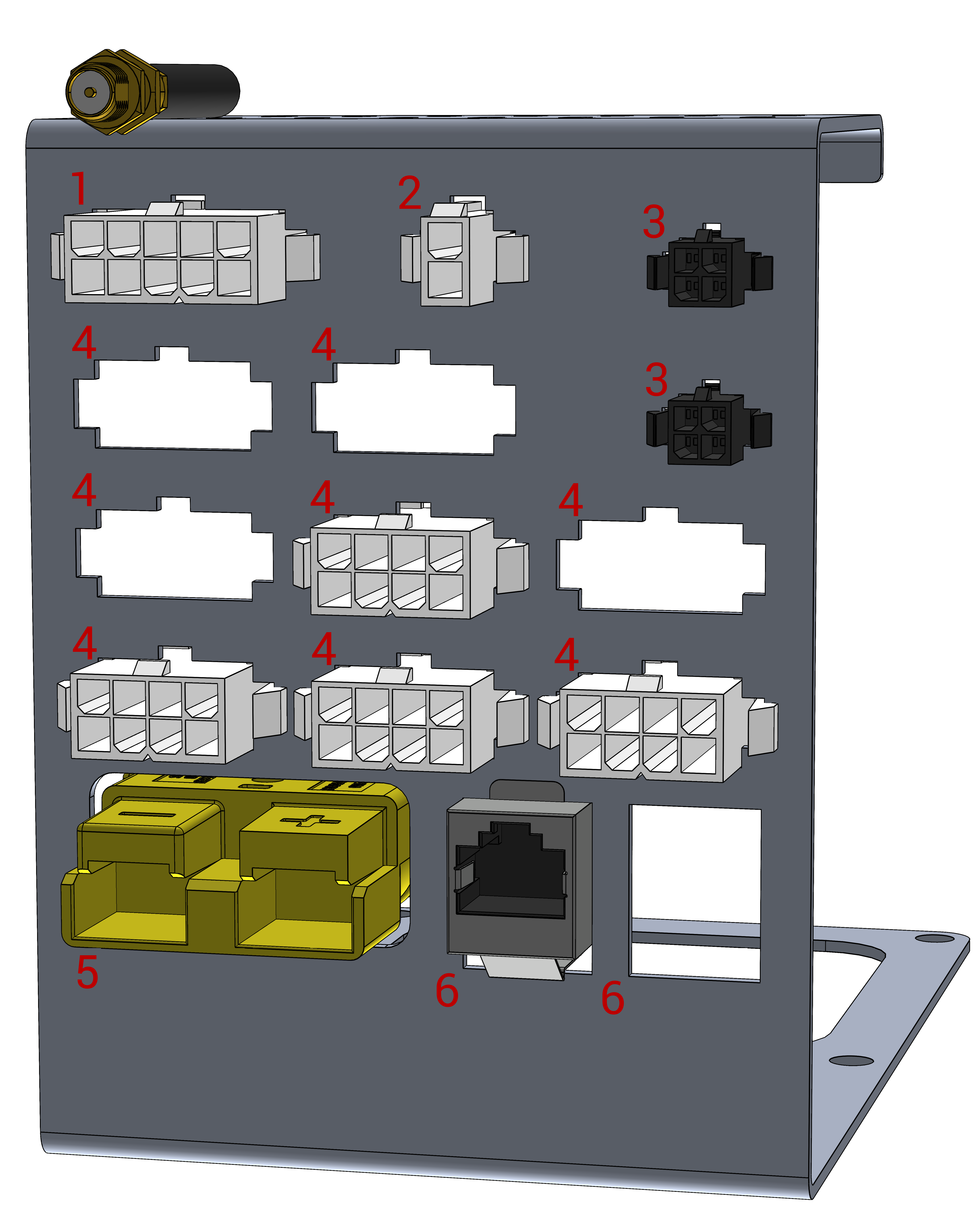
| Row | Interface | Purpose for AMP | Connector on the bulkhead | Mating connector |
|---|---|---|---|---|
| 1 | AUX Outputs | Controlling Lights and Sounder | Molex 0039012106 | Molex 0039012105 |
| 2 | Network Switch Power | Powering the AMP's network switch, and access point | Molex 0039012026 | Molex 0039012025 |
| 3 | Emergency Stop Buttons | 2 additional Emergency Stop Buttons are included with AMP, compared to the base Husky A300. | TE 794615-4 | TE 794617-4 |
| 4 | User Power Connections | The bulkhead includes 8 cutouts for the 8 User Power Connectors from the base Husky A300 System Interface Assembly. These may be populated with an extension cable, if required for your AMP's configuration. | Molex 0039012086 | Molex 0039012080 |
| 5 | High Power Expansion Kit (Large VBAT) | This is not required for a standard Husky AMP. We provide this interface if the High Power Expansion Kit is included in the base Husky A300. | Anderson 992G5-BK | Anderson 992G5-BK |
| 6 | RJ45 Ethernet | This connects the base Husky A300's network switch to the AMP enclosure's network switch. | RJ45 Port | RJ45 Jack |
We add Bluetooth and Wireless E-stop antenna cables on top of the bulkhead using cable ties. This keeps the antennas electrically isolated from the robot's chassis.
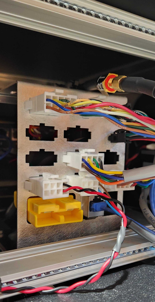
You can add custom cables on top of the bulkhead using tie wraps. You should include an inline connector at this interface for your custom cables, so the enclosure can easily be removed from the base Husky A300 for maintenance.
Removing The Enclosure
To remove the large electronics enclosure:
-
Turn off the Husky.
-
Open the Rear Charge Port Door.
-
Flip the Circuit Breaker to the Off position.
-
Close the Rear Charge Port Door.
-
Remove the Side Panels.
-
Disconnect all the cables from the Base Robot → AMP Enclosure Connector Bulkhead.
-
Remove the seven M6×1 socket head screws that attach the Enclosure to the base robot.
noteThe seventh screw is near the rear-left corner of the robot.
-
Lift the Enclosure off the base robot.
Do not drag the Enclosure on the robot, because it may damage the bulb seal around the Husky's chassis.
When reinstalling the Enclosure:
- Torque the 7 screws to 5 N·m.
- Torque the Side Panel's nuts to 3 N·m.
Arch's Cables
The Sensor Arch places Husky's cameras and GNSS antennas above the robot for optimal view angles. These steps will give you access to the related cable routings for repairs:
- Remove the 3 screws from the inside access panel.
- Remove the panel by sliding it toward the end of the robot.
- The Arch Posts have cable tie anchors. You can remove the cable ties with side cutters.
- Cables route through an obround cutout in the Enclosure.
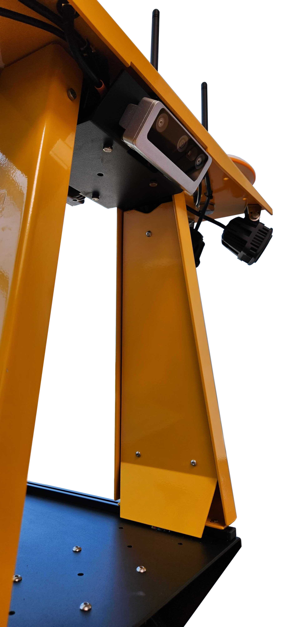
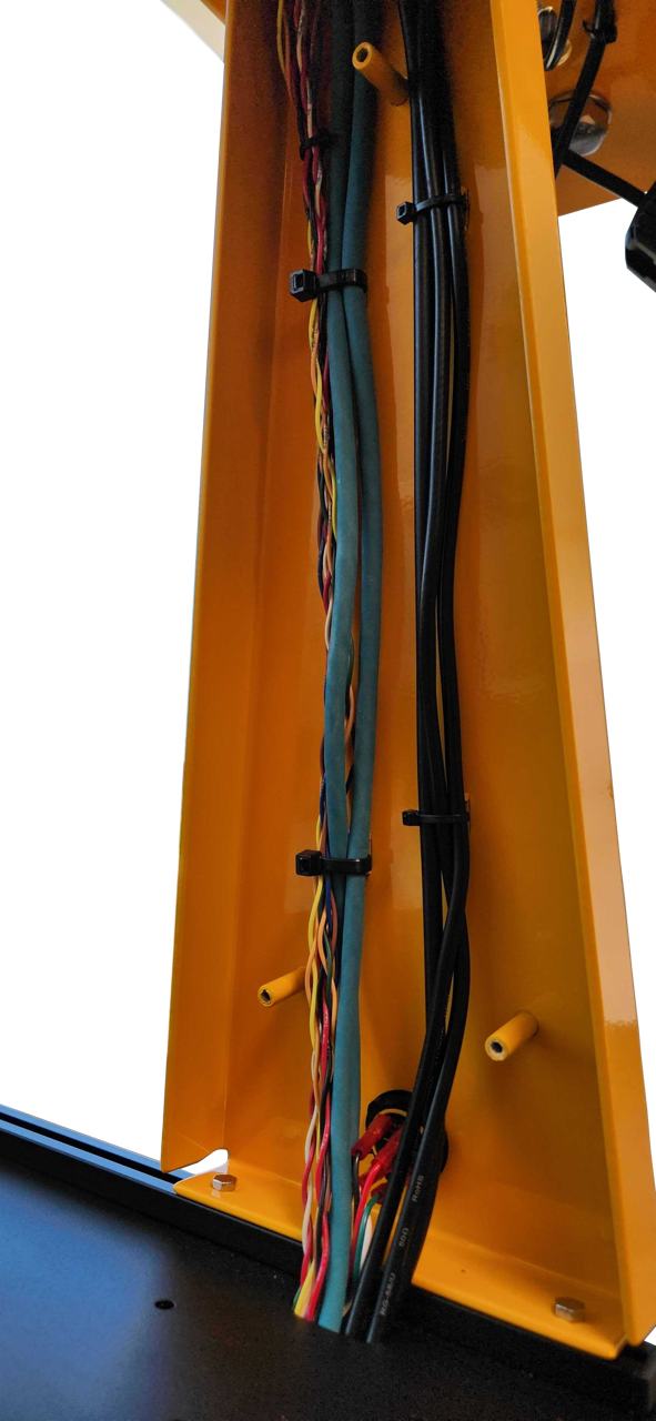
When reinstalling the Access Panels:
- Torque the 3 screws to 1.5 N·m.
The Arch and cables will be exposed to rain. Cables routing into the Enclosure will pass through 3 layers of escalator brushes to maintain the IP54 ingress protection rating.
There is a triangular cutout at the top of the Access Panel. This allows you to route a cable to the optional Ouster lidar kit, or to any sensor you mount under the camera bracket's PACS™ pattern.
AMP's Cable Routings
The AMP's enclosure has brushes on both ends, allowing you to route cables outside the enclosure. There are 3 layers of brushes per side, to limit water ingress. We weave cables through the brushes sideways, to prevent a straight water ingress point.
Test your integration for ingress points by placing a light inside the enclosure, and then looking for light bleed near cables. Adjust your routings till you are confident the integration will prevent water splash ingress in accordance with IPx4.
The enclosure has threaded holes to mount an Icotek KEL-U 24|10 V2A (54241.200). This Icotek housing replaces the AMP enclosure's 3 layers of brushes. You can then use Icotek split grommets to retain cables.
This is not required for most IP54 applications. Brushes are the default configuration for Husky AMP as they simplify integrations.
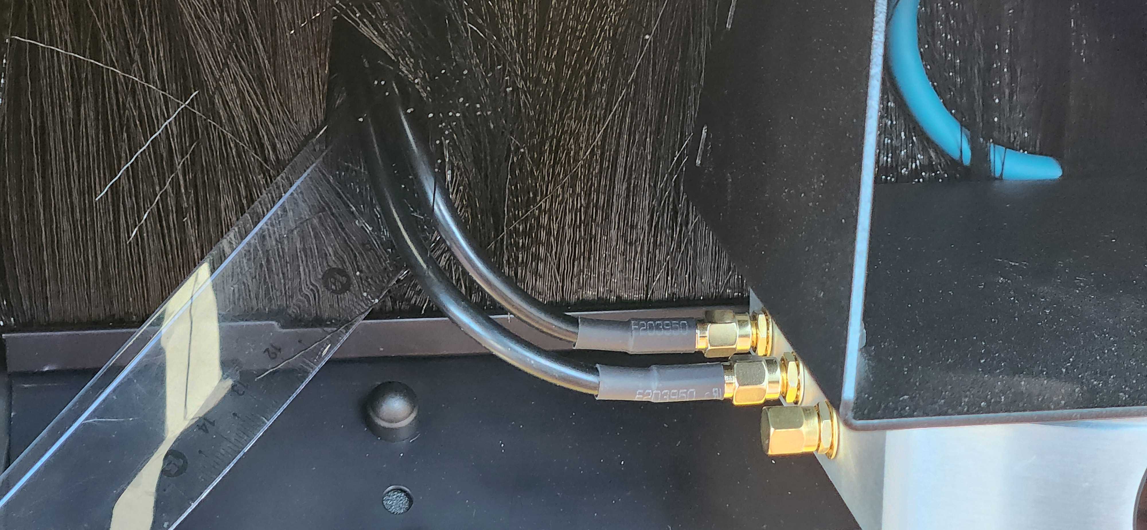
Custom Integrations
DANGER
Always perform a risk assessment prior to any custom integrations.
Custom integrations are outside the scope of the robot's safety assessment, as custom integrations may result in new hazards.
STEP Model
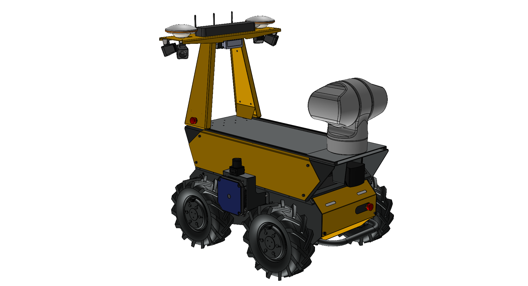
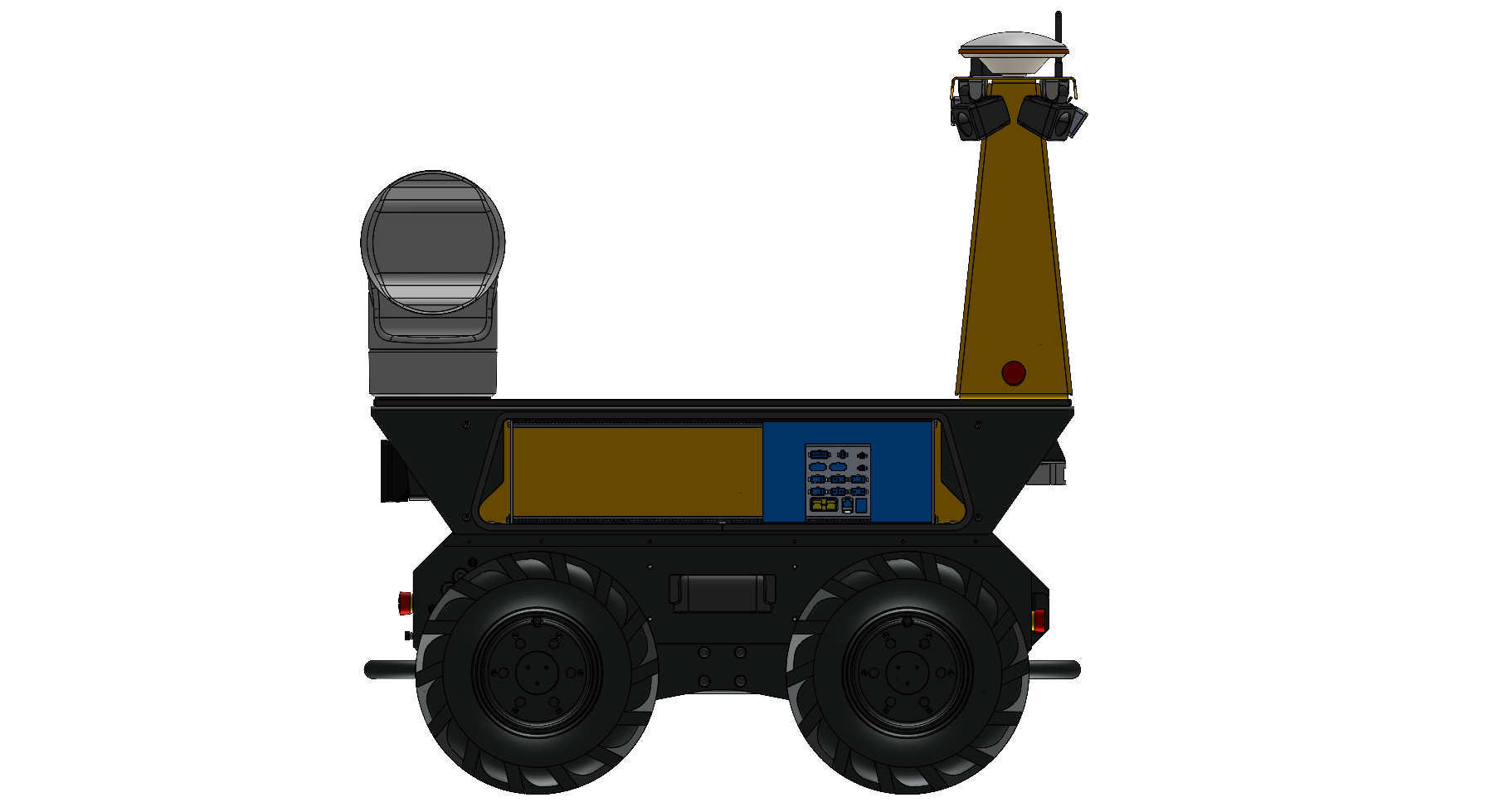
base_link
base_link is the primary coordinate system for the robot.
All sensors, manipulators, and brackets are positioned with reference to base link.
This ROS 2 Documentation page explains how a robot's model is constructed.
Husky's model is included on the robot, and is available on our public GitHub.
Husky's base_link is located on the bottom of the chassis, with +X pointed toward the front panel, and +Y toward the robot's left side.
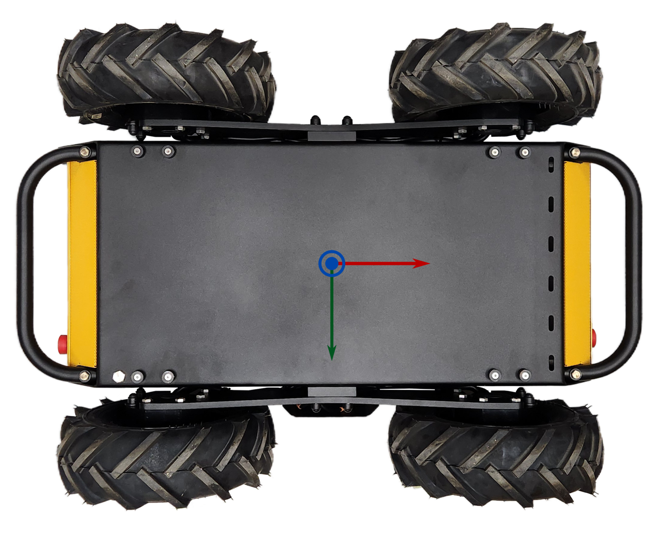
The STEP Model's origin is aligned with base_link.
Internal Integrations
There are interfaces inside the Husky for your custom components. This Interface Control Drawing shows the available volume near the robot's batteries, noting that the size of this volume changes depending on what battery configuration your Husky has—(40 Ah, 80 Ah, or 120 Ah). The drawing also shows mounting provisions on the robot's Electronics Tray, for including these components:
- Husky's System Interface Assembly (circuit board with Husky's microcontroller, power supplies, and motor controllers)
- Primary computer
- IMU
- Add-on secondary computer or graphics card
- Add-on USB hub
Refer to the STEP model for more measurements of the Husky's interface areas.
This integration volume is available inside the base Husky A300, as well as Husky AMP and Husky Observer.
Data Connections
These are our suggested methods for connecting sensors and actuators to Husky.
| Data Bus | Clearpath's suggestion for connecting devices to the Husky's computer: |
|---|---|
| USB | Direct connection to the robot's computer, or add a USB hub. |
| Ethernet | Connect to the robot's 2.5 Gbit/s Ethernet Switch, which is inside the chassis. |
| Serial RS-232, RS-422, RS-485 | Add a USB converter, such as a FTDI cable. Most computers have Serial ports, but these take more time to configure than a FTDI cable. |
| CAN | Add a USB converter, such as a PEAK System PCAN-USB. |
System Interface Connector Summary
The System Interface Assembly is a circuit board that includes power supplies, lighting controllers, motor controllers, and the Husky's microcontroller. This circuit board has connectors for: power, fans, relays, GPIOs, auxiliary inputs, auxiliary outputs, and Emergency Stop devices.
| Purpose | Label on the circuit board | Connector on the circuit board | Mating connector | Mating connector's crimp | Crimping tool |
|---|---|---|---|---|---|
| User Power Connections | USER 1 - USER 8 | Molex 0039296088 | Molex 0039012080 | Molex 0039000140 (AWG 22-28) Or Molex 0039000073 (AWG 18-24) | Molex 0638191000 |
| Expansion Power | EXP 1 - EXP 2 | Molex 1720650202 | Molex 1700010102 | Molex 1720630311 (AWG 14-16) Or Molex 1720630312 (AWG 12) | Molex 2238631200 |
| AUX Inputs | AUX1 IN, AUX2 IN, AUX3 IN | TE 3-794682-6 | TE 794617-6 | TE 1-794606-1 (AWG 20-24) Or TE 1-794607-1 (AWG 26-30) | TE 91391-1 |
| AUX Outputs | AUX1 OUT, AUX2 OUT, AUX3 OUT | TE 3-794682-8 | TE 794617-8 | TE 1-794606-1 (AWG 20-24) Or TE 1-794607-1 (AWG 26-30) | TE 91391-1 |
| GPIO | GPIO | TE 4-794680-6 | TE 1-794617-6 | TE 1-794606-1 (AWG 20-24) Or TE 1-794607-1 (AWG 26-30) | TE 91391-1 |
| Fans | FAN 5 - FAN 8 | Molex 0705430003 | Molex 0050579404 | Molex 0016020103 (AWG 22-24) | Molex 0638118700 |
| Wireless Emergency Stop | W ES (Wireless E-Stop) | TE 4-794682-0 | TE 1-794617-0 | TE 1-794606-1 (AWG 20-24) Or TE 1-794607-1 (AWG 26-30) | TE 91391-1 |
| Emergency Stop Buttons | ES 3 - ES 8 (E-Stop) | TE 3-794682-4 | TE 794617-4 | TE 1-794606-1 (AWG 20-24) Or TE 1-794607-1 (AWG 26-30) | TE 91391-1 |
| Computer Power | SYS1 - SYS 2 | Molex 1720650204 | Molex 1700010104 | Molex 1720630311 (AWG 14-16) Or Molex 1720630312 (AWG 12) | Molex 2238631200 |
| Graphics Card Power | SYS3 | Molex 1720650206 | Molex 1700010106 | Molex 1720630311 (AWG 14-16) Or Molex 1720630312 (AWG 12) | Molex 2238631200 |
| Network Switch Power | SYS4 | Molex 0039281023 | Molex 0039012020 | Molex 0039000140 (AWG 22-28) Or Molex 0039000073 (AWG 18-24) | Molex 0638191000 |
Power Connections
User Power Connections
The System Interface circuit board has 8 User Power connectors, labelled USER 1 through USER 8.
User power is divided into 4 power rails and the power for each rail is shared across each of the 8 connectors. The maximum—(aggregate)—current available on each power rail is outlined in the table below. These circuits are protected with self resetting fuses. These circuits can also be toggled on and off through ROS.
| User Power Rail | Maximum (Aggregate) Current |
|---|---|
| 12 V Rail A | 5 A |
| 12 V Rail B | 5 A |
| 24 V | 5 A |
| VBAT (24 - 29 V, unregulated) | 5 A |
Do not exceed the specified maximum current limit of each power rail. Exceeding the maximum current may damage to your payload.
User Power Pinout
The pinout for each of the 8 connectors—(USER 1 through USER 8)—is illustrated below.
| USER connector pin | Function |
|---|---|
| 1 | 12 V (Rail B) |
| 2 | 12 V (Rail A) |
| 3 | 24 V |
| 4 | VBAT (24 - 29 V, unregulated) |
| 5 | GND |
| 6 | GND |
| 7 | GND |
| 8 | GND |
Making User Power Cables
Connecting to user power requires the use of a Molex connector and compatible crimp terminals. To create these cables, follow the steps below.
- Expose about 5 mm of bare wire from the payload power leads and twist the exposed wire on both leads.
- Take 2 Molex terminals from the spare parts kit provided and insert the exposed wire and crimp the terminals, ensuring the wires are well secured inside the terminal, as shown below.
- Take 1 connector housing from the spare parts kit provided and insert the positive payload power lead—(red)—into position 1, 2, 3 or 4 of the connector until it locks into place. The positions numbers are visible on the back of the plastic housing.
- Insert the negative payload power lead (black) into position 5, 6, 7, or 8 of the connector until it locks into place.
For more technical information on the Molex power connectors, as well as their corresponding mating connectors, please visit the Digi-Key WM3703-ND Product Page.
Software Control of User Power Rails
User power can be enabled or disabled through ROS by publishing to /a300_#####/platform/mcu/cmd_user_power ROS topic.
-
To disable user power, run:
ros2 topic pub --once /a300_#####/platform/mcu/cmd_user_power std_msgs/msg/Bool '{data: false}' -
To enable user power, run:
ros2 topic pub --once /a300_#####/platform/mcu/cmd_user_power std_msgs/msg/Bool '{data: true}'
User Power is enabled by default shortly after the robot first powers up, regardless of its state when the robot was powered off.
Expansion Power (EXP 1 and EXP 2)
There are 2 Expansion Power connectors on the System Interface circuit board. The Expansion Power connectors can power small manipulators, DC-AC inverters, and DC-DC supplies.
These connectors supply VBAT voltage, with a combined current of up to 20 A. The connectors also include soft-start circuitry which limits inrush current to 25 A. This soft-start circuit reduces the chance of a high capacitance load causing the 20 A fuse to pop.
Use a Littelfuse 0297020.U as the replacement.
Expansion Power Pinout
The pinout for each of the 2 connectors—(EXP 1 and EXP 2)—is illustrated below.
| Expansion Power connector pin | Function |
|---|---|
| 1 | VBAT (24 - 29 V, unregulated) |
| 2 | GND |
Software Control of Expansion Power Rails
The Expansion Power connectors are connected to the same control system as the User Power. Refer to the Software Control of User Power Rails section for details.
High Power Expansion Kit (Large VBAT)
The optional High Power Expansion Kit can purchased at the time of your original Husky order—(Clearpath item 032001). We do not allow field installation of the kit.
We suggest you purchase a 80 Ah or 120 Ah Husky if you plan to operate on hills steeper than 5°, and have a payload of more than 50kg. 40 Ah battery configuration may not provide enough power in the worst case. Contact Support for more details.
Some high power payloads, such as manipulators, require more power than can be provided through the User Power connectors. The optional High Power Expansion Kit provides VBAT voltage at 40 A. It also includes 2 contactors for enabling and disabling power to the payload.
Making A Large VBAT Cable
We suggest using #10 AWG wire for this cable routing if it is completely inside the robot's chassis. We suggest using #8 AWG wire for this cable routing if it is outside the chassis, where someone could touch the cable. #8 AWG surface temperature is acceptable in an exposed cable for 40 A, per UL 1740.
The mating cable will connect to the yellow Anderson Power Products SB50 connector in left-rear of the robot's chassis, under the Top Plate.
Always observe local laws and electrical standards when building cables.
Consult the manufacturer's documentation for full details on proper crimping.
| Description | Vendor Part | CPR Part Number |
|---|---|---|
| Mating connector | Anderson 992G5-BK | 022554 |
| Crimps, #8 AWG | Anderson 5952-BK | 017281 |
| Crimps, #10 - #12 AWG | Anderson 5953-BK | 022562 |
| Crimping tool | Anderson 1309G4 | N/A |
Use a Littelfuse 142.5631.5402 as the replacement.
On/Off Control via Software
The High Power Expansion Kit output is controlled through software by publishing to the ROS topic /a300_#####/platform/mcu/cmd_high_power,
similar to Software Control of User Power Rails.
The High Power Expansion Kit output is always disabled when the system powers up. You must enable the output, via the ROS topic above, each time after the system powers up.
AUX Inputs
The System Interface circuit board has 3 auxiliary inputs—(AUX1 IN, AUX2 IN, AUX3 IN)—that allow external payloads to provide inputs to the robot. Each of these auxiliary inputs can be driven by one of the following:
- a 12 V input
- a 24 V input
- a push button or switch
The state of the input can be read from the ROS topic /a300_#####/platform/mcu/status/aux_inputs.
The AUX inputs are active low and are mapped to the ROS message bits as follows:
- AUX1 IN: bit 0
- AUX2 IN: bit 1
- AUX3 IN: bit 2
| AUX Input | Payload State | /a300_#####/platform/mcu/status/aux_inputs Value |
|---|---|---|
| AUX1 IN | 24 V on OR 12 V on OR button pressed 24 V off AND 12 V off AND button not pressed | bit 0 reads as '0' bit 0 reads as '1' |
| AUX2 IN | 24 V on OR 12 V on OR button pressed 24 V off AND 12 V off AND button not pressed | bit 1 reads as '0' bit 1 reads as '1' |
| AUX3 IN | 24 V on OR 12 V on OR button pressed 24 V off AND 12 V off AND button not pressed | bit 2 reads as '0' bit 2 reads as '1' |
AUX Input Pinout
The pinout for each of the connectors—(AUX1 IN, AUX2 IN, AUX3 IN)—is illustrated below.
| AUX IN Connector's Pin | Function |
|---|---|
| 1 | 24 V In |
| 2 | 12 V In |
| 3 | Button/Switch In, (3.3 V) |
| 4 | 24 V Return |
| 5 | 12 V Return |
| 6 | GND |
AUX Input Example #1
Consider the example where AUX2 IN has a 12 V supply connected to pins 2 and 5, with the remaining pins unconnected.
Monitor the input reading in ROS.
ros2 topic echo /a300_#####/platform/mcu/status/aux_inputs
| Action | /a300_#####/platform/mcu/status/aux_inputs value | Bit 2 Explanation | Bit 1 Explanation | Bit 0 Explanation |
|---|---|---|---|---|
| Begin with the 12 V supply turned off | 7 (8b00000111) | '1' since AUX3 IN is not connected | '1' since 12 V supply is off | '1' since AUX1 IN is not connected |
| Turn the 12 V power supply on | 5 (8b00000101) | '1' since AUX3 IN is not connected | '0' since 12 V supply is on | '1' since AUX1 IN is not connected |
| Turn the 12 V supply off | 7 (8b00000111) | '1' since AUX3 IN is not connected | '1' since 12 V supply is off | '1' since AUX1 IN is not connected |
AUX Input Example #2
Consider the example where AUX1 IN has a 24 V supply connected to pins 1 and 4, AUX2 IN has a 12 V supply connected to pins 2 and 5, and AUX3 IN has a push button connected to pin 3.
| Action | /a300_#####/platform/mcu/status/aux_inputs value | Bit 2 Explanation | Bit 1 Explanation | Bit 0 Explanation |
|---|---|---|---|---|
| Begin with 12 V supply turned off, the 24 V supply off, and the button not pressed | 7 (8b00000111) | '1' since button is not pressed | '1' since 12 V supply is off | '1' since 24 V supply is off |
| Turn the 24 V power supply on | 6 (8b00000110) | '1' since button is not pressed | '1' since 12 V supply is off | '0' since 24 V supply is on |
| Turn the 12 V supply on | 4 (8b00000100) | '1' since button is not pressed | '0' since 12 V supply is on | '0' 24 V supply is on |
| Press and hold the button | 0 (8b00000000) | '0' since button is pressed | '0' since 12 V supply is on | '0' 24 V supply is on |
AUX Outputs
The System Interface circuit board includes 3 outputs—(AUX1 OUT, AUX2 OUT, AUX3 OUT)—that can be controlled by publishing to the /a300_#####/platform/mcu/cmd_aux_outputs ROS topic.
To enable the AUX outputs, publish a single message with the appropriate bits set to 1 to turn the output on, and 0 to turn it off.
The state does not persist so new commands will need to keep the bit enabled as well.
The AUX outputs are mapped to the ROS message bits as follows:
- AUX1 OUT: bit 0
- AUX2 OUT: bit 1
- AUX3 OUT: bit 2
AUX Output Pinout
Each of the AUX outputs is an 8 position connector with pinout as outlined below. The output value is available in several modes:
- MOSFET outputs, (2X)
- Normally open relay
- Normally closed relay
| AUX OUT Connector Pin | Name | Function | Output when corresponding cmd_aux_outputs bit is '0' | Output when corresponding cmd_aux_outputs bit is '1' |
|---|---|---|---|---|
| 1 | AUX_24V | 24 V output, fused at 3 A | 24 V | 24 V |
| 2 | GND | GND | GND | GND |
| 3 | AUX_RELAY_NC | Normally closed relay pin | Connected to AUX_RELAY_COMMON | Floating |
| 4 | AUX_MOSFET2 | MOSFET #2 DRAIN | GND | Floating |
| 5 | GND | GND | GND | GND |
| 6 | AUX_RELAY_COMMON | Input that gets connected to AUX_RELAY_NC or AUX_RELAY_NO | Connected to AUX_RELAY_NC | Connected to AUX_RELAY_NO |
| 7 | AUX_RELAY_NO | Normally open relay pin | Floating | Connected to AUX_RELAY_COMMON |
| 8 | AUX_MOSFET1 | MOSFET #1 DRAIN | GND | Floating |
AUX Output Examples
-
To enable the AUX1 output:
ros2 service call /a300_#####/platform/pinout/aux_1 clearpath_platform_msgs/srv/SetPinout "{state: true, toggle_period: 0}" -
To disable the AUX1 output:
ros2 service call /a300_#####/platform/pinout/aux_1 clearpath_platform_msgs/srv/SetPinout "{state: false, toggle_period: 0}"
General Purpose Inputs and Outputs (GPIO)
The System Interface circuit board includes 4 general purpose inputs, and 4 general purpose outputs.
All GPIOs are at the 3.3 V logic level.
General purpose inputs are readable from the /a300_#####/platform/mcu/status/gp_inputs ROS topic.
Publishing to the /a300_#####/platform/mcu/cmd_gp_outputs ROS topic controls the general purpose outputs.
All the inputs and outputs are exposed through a single connector.
General Purpose Input Pinout
| GPIO connector pin | Function | gp_inputs value when driven at 0 V | gp_inputs value when driven at 3.3 V |
|---|---|---|---|
| 5 | GP In 1 | Bit 0 is '0' | Bit 0 is '1' |
| 6 | GP In 2 | Bit 1 is '0' | Bit 1 is '1' |
| 7 | GP In 3 | Bit 2 is '0' | Bit 2 is '1' |
| 8 | GP In 4 | Bit 3 is '0' | Bit 3 is '1' |
| 13 | GND | N/A | N/A |
| 14 | GND | N/A | N/A |
| 15 | GND | N/A | N/A |
| 16 | GND | N/A | N/A |
General Purpose Output Pinout
| GPIO connector pin | Function | Corresponding bit in cmd_gp_outputs | Output value when set to '0' | Output value when set to '1' |
|---|---|---|---|---|
| 1 | GP Out 1 | 0 | 0 V | 3.3 V |
| 2 | GP Out 2 | 1 | 0 V | 3.3 V |
| 3 | GP Out 3 | 2 | 0 V | 3.3 V |
| 4 | GP Out 4 | 3 | 0 V | 3.3 V |
| 9 | GND | N/A | GND | GND |
| 10 | GND | N/A | GND | GND |
| 11 | GND | N/A | GND | GND |
| 12 | GND | N/A | GND | GND |
Fan Expansion
The System Interface circuit board has support for 4 additional 12 V brushless 4-wire PWM fans. Ports FAN 1, FAN 2, FAN 3, and FAN 4 are already used by the base Husky A300. Ports FAN 5, FAN 6, FAN 7, and FAN 8 are available for your fan expansions.
The pinout for each fan is:
| Pin | Function |
|---|---|
| 1 | 12 V |
| 2 | GND |
| 3 | Tachometer (output from fan) |
| 4 | PWM (input to fan, 3.3 V) |
The speed of each fan can be controlled by publishing to the /a300_#####/platform/mcu/cmd_fans ROS topic.
The speed of each fan can be monitored by reading the /a300_#####/platform/mcu/status/fans ROS topic.
In both cases, the fan value is in the range from 0 (not spinning), to 255 (max speed).
Fans require spool up time on startup. Setting a fan to a very low value may result in the fan not rotating. You should experiment to find minimum PWM value that causes your fan to spin.
CANbus Connection
Husky has up to 3 standard CAN networks:
| Network name | Data Rate | Purpose | Devices |
|---|---|---|---|
vcan0 | 1000 kBit/s | Motor Control | Primary Computer, MCU, 4 Motor Controllers |
vcan1 | 250 kBit/s | Batteries | Primary Computer, MCU, Batteries (up to 6 batteries), Wireless Emergency Stop |
usbcan0 | 250 kBit/s | Optional Wireless Charger | Primary Computer, Wireless Charger |
We suggest you add custom CAN devices to a new network, using a USB-CAN adapter such as a PEAK System PCAN-USB. You would need to name the new network something different than the 3 networks listed above. We configure these networks using SocketCAN.
It is possible to add new devices to the Husky's existing networks, but this requires significant testing time.
Additional Emergency Stop Devices
The base Husky A300 includes 2 Emergency Stop Buttons, which are connected to the System Interface circuit board. The System Interface circuit board also includes connector breakouts for 6 more Emergency Stop devices, labelled ES3 through ES8. The standard Husky A300 has a bypass jumper inserted into each of these unused Emergency Stop breakouts.
You can use these Emergency Stop breakouts to add more Emergency Stop devices, such as:
- Emergency Stop buttons
- Safety lidar
- Tape switches
- Limit switches
- Relays or similar PLC components
- Manipulator control cabinets
| ES Pin | Function / Value |
|---|---|
| 1 | Channel 1 Out, (24 V): normally connected to Channel 1 In; disconnect to trigger an emergency stop |
| 2 | Channel 1 In |
| 3 | Channel 2 Out (24 V): normally connected to Channel 2 In; disconnect to trigger an emergency stop |
| 4 | Channel 2 In |
System Power
These 4 connectors collectively provide up to 400 W of power at 12 V for powering computers and network equipment.
SYS1 And SYS2 Pinouts For Computers
| Pin | Function / Value |
|---|---|
| 1 | 12 V |
| 2 | 12 V |
| 3 | GND |
| 4 | GND |
SYS1 is always being used by the robot's Primary Computer.
SYS3 Pinout For A Graphics Card
| Pin | Function / Value |
|---|---|
| 1 | 12 V |
| 2 | 12 V |
| 3 | 12 V |
| 4 | GND |
| 5 | GND |
| 6 | GND |
SYS4 System Power For A Network Switch
This provides 60 W of power at 12 V.
| Pin | Function / Value |
|---|---|
| 1 | 12 V |
| 2 | GND |
AMP's Interface Control Drawing (ICD)
This Interface Control Drawing shows these Husky AMP details:
- Internal Eurorack, and available volume for your custom integrations
- Cable Routing Path
- Aluminum Extrusions
- Large Component Mounts
- Connector Bulkhead, between the base Husky A300, and the AMP's enclosure
- PACS mount on the bottom of the Arch
- Allowable locations for the Arch
Refer to the STEP model for more measurements of the Husky AMP's interface areas.
AMP's Eurorack Interface, For Custom Electronics
The Husky AMP's enclosure includes a metal rack with many M3×0.5 threaded holes. The spacing of these holes conform to the Eurorack 3U standard. You can create your own modules to interface with this rack, or purchase modules from Clearpath.
The STEP model includes this rack, as well as a volume representing the modules that are required for the Husky AMP's sensors.
Digikey sells 3U metal panels, such as this series from Wakefield-Vette.
Details
| HP Width | Wakefield-Vette Item |
|---|---|
| 2 | 3684.889 |
| 3 | 3684.890 |
| 4 | 3684.891 |
| 5 | 3684.892 |
| 6 | 3684.893 |
| 7 | 3684.894 |
| 8 | 3684.895 |
| 10 | 3684.896 |
| 12 | 3684.897 |
| 14 | 3684.898 |
| 20 | 3684.899 |
| 21 | 3684.900 |
| 27 | 3684.901 |
| 28 | 3684.902 |
| 40 | 3684.903 |
| 42 | 3684.904 |
| 60 | 3684.905 |
| 63 | 3684.906 |
| 84 | 3684.907 |
| 85 | 3684.744 |
AMP's Aluminum Extrusions
There are two aluminum extrusions on the top of the Husky AMP's enclosure. The centre of these extrusions are spaced 340 mm apart. The extrusions accept Misumi 5 Series T-slot Nuts. These are intended as an interface for light components, since the rails are attached with six M3×0.5 screws.
Here are some of the Misumi T-slot fasteners we use:
| Clearpath Item | Misumi Item | Description |
|---|---|---|
| 021464 | HNTASN5-5 | M5×0.8 nut, without retention |
| 028825 | SHNTP5-5 | M5×0.8 nut, with ball plunger retention |
| 026955 | SHNTAP5-5 | M5×0.8 nut, with leaf spring retention |
| 001018 | HATLSN5-4-12 | M5×0.8 stud, without retention |
Large Component Mounts, Like Arms / Manipulators
There is a grid of Ø5 mm holes on the top of the enclosure, near the front and rear edges. These holes have a pitch of 80 mm, same as Clearpath's PACS™ system. The holes are located near the enclosure's weld seams, to improve stiffness between the large component and the Husky's wheels.
Software Integration
ROS has a large ecosystem of sensor drivers, some of which include pre-made URDF descriptions and even simulation configurations. Refer to Sensors supported by ROS.
For the best experience, consider purchasing supported accessories from Clearpath Robotics for your robot, which will include simulation, visualization, and driver support.
Refer to the following for more details:
Custom Robot Panel Colour
Your robot's yellow panels can be swapped for a custom colour. We use TIGER Drylac powder coating on these parts. TIGER has a wide range of colours, though some are special order.
Talk to a Clearpath Robotics salesperson to discuss custom colour prices and lead times: research-sales@clearpathrobotics.com
Support
Clearpath is committed to your success. Please get in touch with us and we will do our best to get you rolling again quickly: support@clearpathrobotics.com.
To get in touch with a salesperson regarding Clearpath Robotics products, please email research-sales@clearpathrobotics.com.
If you have an issue that is specifically about ROS and is something which may be of interest to the broader community, consider asking it on Robotics Stack Exchange. If you do not get a satisfactory response, please ping us and include a link to your question as posted there. If appropriate, we will answer on Robotics Stack Exchange for the benefit of the community.