Dingo User Manual
Introduction
Dingo is a lightweight and easy-to-use unmanned indoor ground vehicle for ROS.
There are two Dingo variants:
- Dingo-D uses differential drive and has two module bays, one of which must be a battery module; the second module is typically a computer module.
- Dingo-O uses omnidirectional drive and has four module bays, at least two of which are typically battery modules; the other modules may be computer modules or networking equipment.
Mobile robots are inherently hazardous. It is the responsibility of the deployer to ensure that all personnel that may come into contact with the system are trained properly. It is also the responsibility of the deployer to understand the hazards presented and to ensure sufficient safeguards or other mitigations are in place. Refer to the Safety section of this manual for further details.
Shipment Contents
Your Dingo shipment contains the following:
- Dingo 1.0
- Dingo 1.5
- Dingo UGV (Dingo-D or Dingo-O variant)
- One or more batteries of the following type:
- 12 V sealed lead-acid (SLA) batteries
- 14.4 V lithium batteries
- One or more universal chargers for your batteries
- One Sony PS4 Bluetooth controller
- One Dingo quick start guide
- Accessories:
- USB cable (x1): USB Cable, Type A to Micro B (0.3 m)
- Molex connectors (x2): Molex P/N - 0039012040
- Molex crimp pins (x8): Molex P/N - 0039000073
- Fuse 5A (x1): Littelfuse Inc. P/N - 0891005.NXS
- Fuse 10A (x1): Littelfuse Inc. P/N - 0891010.NXS
- Fuse 20A (x1): Littelfuse Inc. P/N - 0891020.NXS
- Fuse 30A (x1): Littelfuse Inc. P/N - 0891030.NXS
- Dingo UGV (Dingo-D or Dingo-O variant)
- One or more batteries of the following type:
- 12 V sealed lead-acid (SLA) batteries
12.8 V LiFEPO4 batteries
- One universal charger for your batteries
- One Sony PS4 Bluetooth controller
- One Dingo quick start guide
- Accessories:
- USB cable (x1): USB Cable, Type A to Micro B (0.3 m)
- Molex connectors (x2): Molex P/N - 0039014041
- Molex crimp pins (x8): Molex P/N - 0039000073
- Fuse 5A (x1): Littelfuse Inc. P/N - 0891005.NXS
- Fuse 10A (x1): Littelfuse Inc. P/N - 0891010.NXS
- Fuse 20A (x1): Littelfuse Inc. P/N - 0891020.NXS
If you elected to purchase standard payload modules or custom integration services with Dingo, then additional equipment will be included per your specific configuration, plus further documentation as required.
Hardware Overview
System Architecture
Dingo is built around a computer running Ubuntu (Intel-based computer or Jetson developer kit), paired with a 32-bit microcontroller MCU. The MCU handles I/O, power supply monitoring, and motor control, as well as supplying data from the integrated IMU. The communication channel between the MCU and computer is a 100 Mbps Ethernet connection.
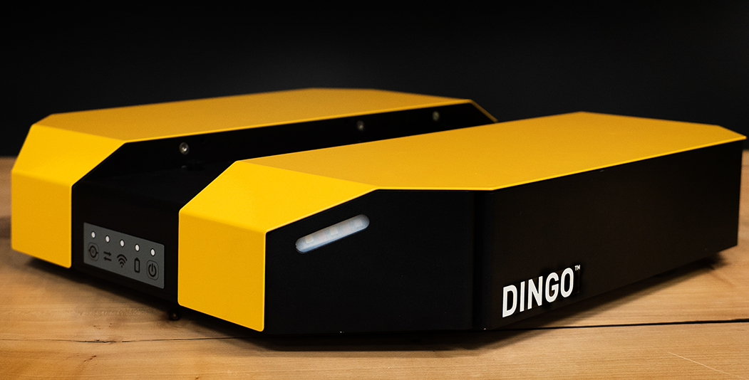
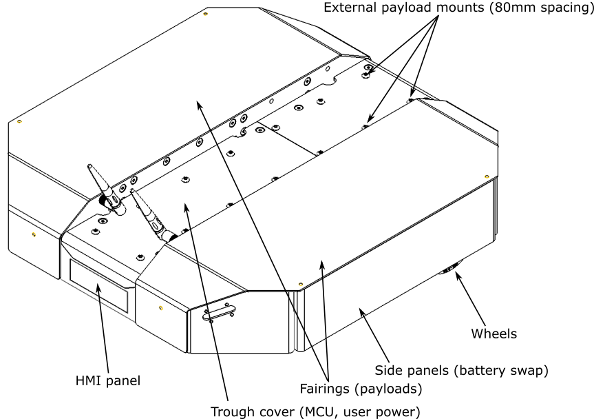
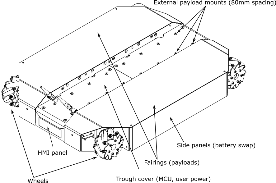
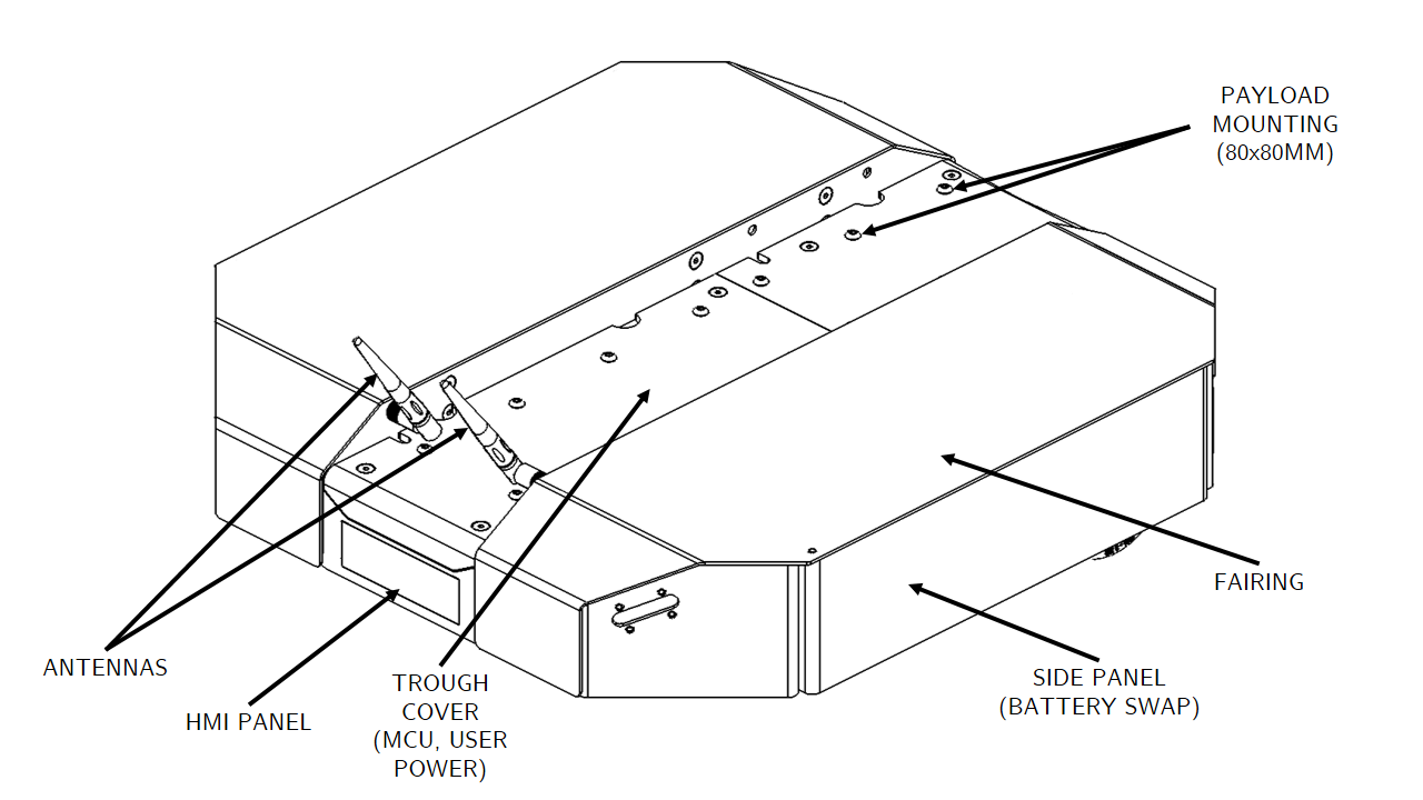
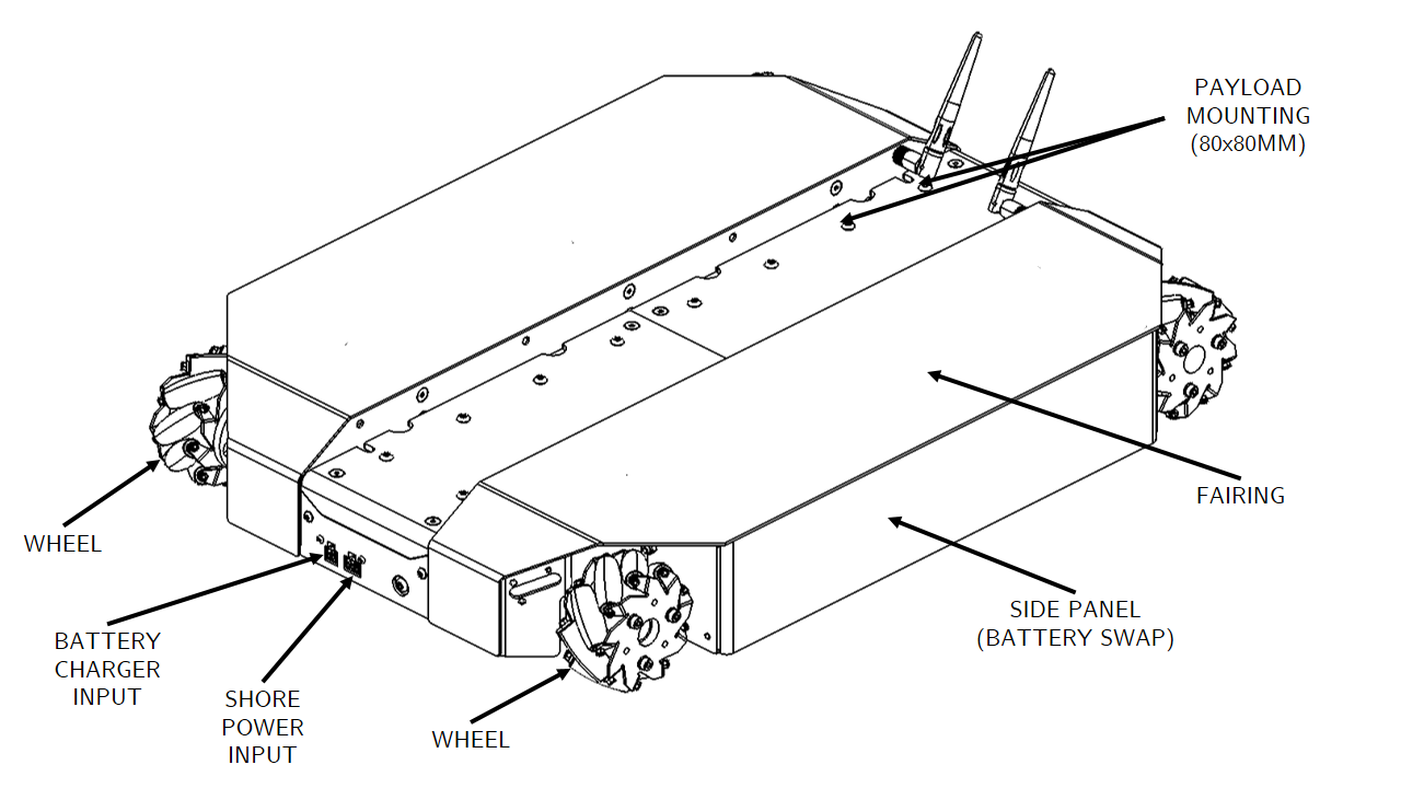
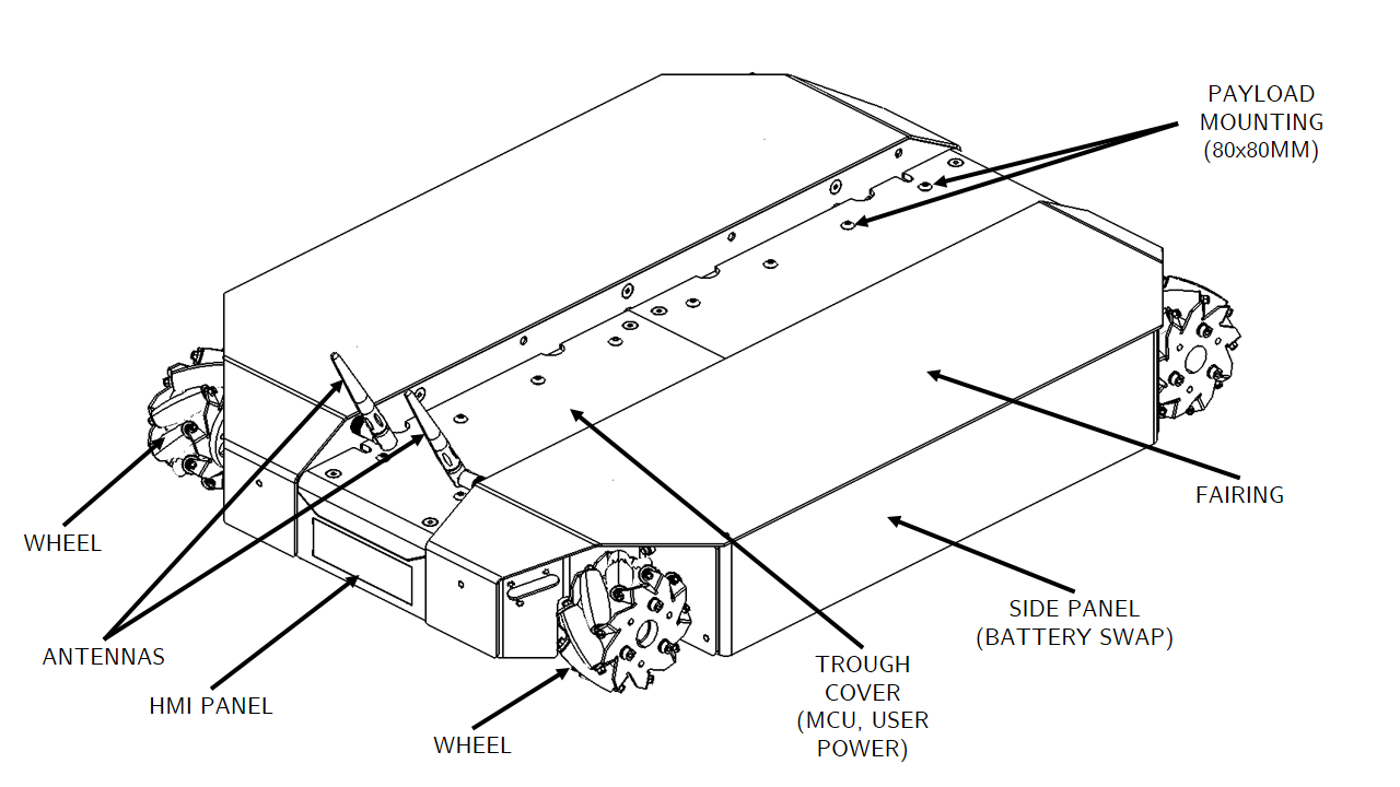
Exterior Features
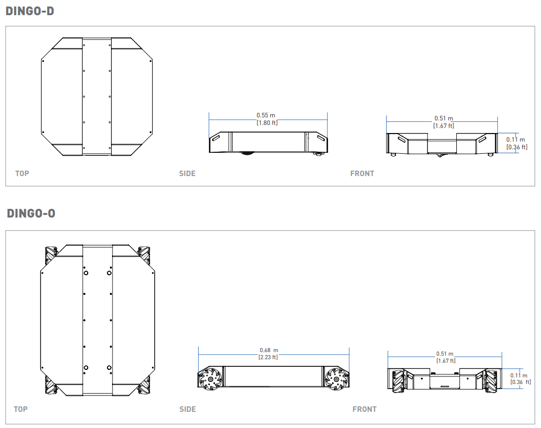
The exteriors of Dingo-D and Dingo-O are shown below and include:
- External payload mounts on the top trough cover;
- 98.4 mm diameter wheels (Dingo-D) or 101.6 mm diameter mecanum wheels (Dingo-O);
- Human machine interface panel (HMI);
- Top (yellow) fairings;
- Side access panels;
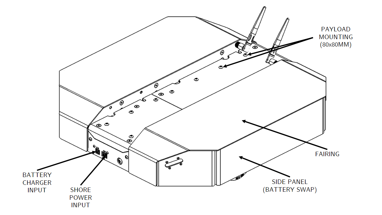
- Front panel connectors (Dingo 1.5 only):
- Wired battery charger port
- DC shore power port
- WiBotic wireless battery charge port (optional, not shown)
- Dingo 1.0
- Dingo 1.5
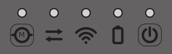
Human-Machine Interface (HMI) Details
The human-machine-interface (HMI) panel is shown below and includes from left:
| Icon | Description |
|---|---|
| Motion Stop button: LED is solid green when Dingo is able to drive and is flashing green when the Dingo's motors are disengaged; pressing button toggles the motors between engaged and disengaged mode (further details in Motion Stop Buttons); LED is not illuminated when connected to DC shore power or to the wired charger (as the robot is prevented from moving in this state) | |
| Comms indictor: LED is solid green when communication between the MCU and computer has been established and LED is off otherwise | |
| Wi-Fi indicator: LED is solid green when Wi-Fi is connected and LED is off otherwise | |
| Battery indicator: LED is solid green when the battery level is ok, flashing green when connected to DC shore power, solid yellow when the battery level is getting low (should be charged soon), and solid red when the battery level is critical (should be charged immediately) | |
| System Power button: LED is solid blue when the system is powered on and running and the LED is flashing blue during the shutdown process; when the system is powered off, pressing the power button begins the power on process; when the system is powered on, a quick press of the power button begins a graceful shutdown and a prolonged press of the power button triggers and immediate power off of the system |
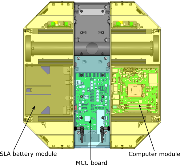
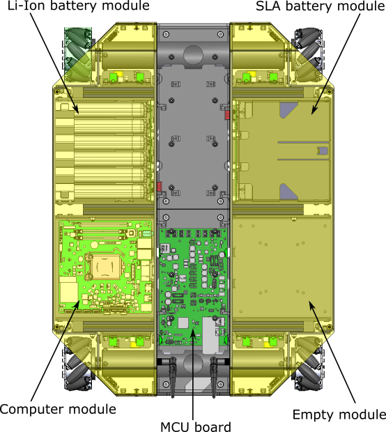
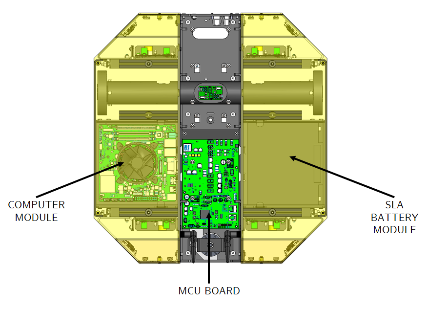
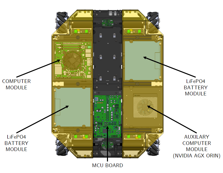
Payload Details
The interiors of Dingo-D and Dingo-O are shown below along with example payload modules.
To access Dingo's payload modules (computers or batteries), simply slide and remove the top (yellow) fairings. To access Dingo's MCU PCBA (for user power), remove the four M5 flathead screws from the top trough cover, and then remove the trough cover.
- Dingo 1.0
- Dingo 1.5
Corner LEDs and System State
Dingo is equipped with LEDs at the four corners of the robot, which indicate the state of the system:
- 0.2.4 Firmware
- 0.3.0 firmware
| System State (lowest to highest priority) | Corner LED Output |
|---|---|
| Idle | Front LEDs solid white (low intensity), rear LEDs solid red (low intensity) |
| Driving | Front LEDs solid white (medium intensity), rear LEDs solid red (medium intensity) |
| Low Battery | Pulsing orange LEDs |
| Reset Required | Adjacent corners alternating between red and off |
| Motion Stop Engaged | Flashing red LEDs |
| System Fault | Flashing orange LEDs |
| System State (lowest to highest priority) | Corner LED Output |
|---|---|
| Idle | Front LEDs solid white (low intensity), rear LEDs solid red (low intensity) |
| Driving | Front LEDs solid white (medium intensity), rear LEDs solid red (medium intensity) |
| Low Battery | Pulsing orange LEDs |
| Reset Required | Adjacent corners alternating between red and off |
| Motion Stop Engaged | Flashing red LEDs |
Charging: wired or wireless (Dingo 1.5 only) | Pulsing green LEDs |
| Shore Power Connected | Pulsing blue LEDs |
Shore Power Connected and Charging (Dingo 1.5 only) | Pulsing green to blue LEDs |
| Puma Fault | Flashing red LED on Puma at fault, solid red for other corners |
Shore Power Fault (Dingo 1.5 only) | Flashing blue and red LEDs |
| Battery Fault | Flashing yellow and red LEDs |
| LED Command Timeout | Solid red |
While in "Idle" and "Driving" states, the user can override the LEDs by publishing to the /mcu/lights topic.
DC Shore Power
Dingo provides a DC Shore Power connection (internal connector for Dingo 1.0; external connector for Dingo 1.5) to allow the system to be powered without requiring batteries to be present. Note that when DC Shore Power is connected, the motors are disabled and it is not possible to drive the Dingo; however, all other electronics (computers, sensors, etc) will remain enabled.
- Dingo 1.0
- Dingo 1.5
For Dingo 1.0, to connect the shore power, remove the top trough cover (to access the MCU) and then attach the shore power cable to the 2-port connector labelled "SHORE" on the MCU.
For Dingo 1.5, users can also connect the manual charger while using DC Shore Power to allow the batteries to charge fully with no load present on them. The DC Shore Power supply is an off the shelf Mean Well power supply, part number GST280A15-C6P. This power supply is a 15V, 225W AC/DC converter with a 6 position Molex connector that plugs into the mating port on the front of the Dingo.
Orientation References
The reference frame used by all Clearpath Robotics ground robots is based on ISO 8855.
When commanded with a positive translational velocity (forward), wheels travel in the positive X-direction. The direction of the axes differs from those used for roll, pitch, and yaw in aircraft, and care should be taken to ensure that data is interpreted correctly.
System Specifications
| Specification | Dingo-D (Differential Drive) | Dingo-O (Omnidirectional Drive) |
|---|---|---|
| Dimension, Length | 551 mm | 686 mm |
| Dimension, Width | 517 mm | 517 mm |
| Dimension, Height | 110 mm | 114 mm |
| Ground Clearance | 14 mm | 16 mm |
| Mass | 12 kg | 17.5 kg |
| Maximum Modules | 2 | 4 |
| Maximum Payload | 20 kg | 25 kg |
| Speed, Maximum | 1.3 m/s | 1.3 m/s |
| Operating Environment | Indoor | Same as Dingo-D |
| Operating Time (Dingo 1.0) | 2 hours (1X SLA), 4 hours (1X Lithium) | 2 hours (2X SLA), 4 hours (2X Lithium) |
| Operating Time (Dingo 1.5) | 2 hours (1X SLA), 4 hours (1X LiFEPO4) | 2 - 6 hours (1X - 3X SLA), 3.5 - 11 hours (1X - 3X LiFEPO4) |
| Battery Chemistry | Sealed Lead-Acid or Lithium (Dingo 1.0) / LiFEPO4 (Dingo 1.5) | Same as Dingo-D |
| Charge Time | 3.3 hours (1X SLA) or 3.0 hours (1X LiFEPO4) | 3.3 - 10 hours (1X - 3X SLA) or 3 - 9 hours (1X - 3X LiFEPO4) |
| User Power (Dingo 1.0) | 20 A @ VBAT (11 - 16.8 V), 7A @ 12 V, 5 A @ 5 V | Same as Dingo-D |
| User Power (Dingo 1.5) | 20 A @ VBAT (11 - 15 V), 10A @ 12 V, 5 A @ 5 V | Same as Dingo-D |
| Communication | Ethernet, USB 3.0 | Same as Dingo-D |
| Internal Sensing | Battery Status, Wheel Odometry, Motor Currents, Onboard IMU | Same as Dingo-D |
Getting Started
You are ready to go! This section details how to get Dingo into action. To begin, place Dingo "up on blocks" as described in the Safety section, making sure that the wheels are clear of the ground.
For most Dingo setups, there will be an Onboard Computer which is directly connected to the Dingo and an Offboard Computer which is used to control Dingo and gather data. These two computers must be set up to communicate with each other.
Onboard Computer Setup
If you purchased an Onboard Computer from Clearpath Robotics with Dingo, it is already installed, connected, and powered. If not, or to set up your own Onboard Computer, see the Dingo Tutorials.
Note that the Onboard Computer must be connected to Dingo's Ethernet port, which is accessible in the center channel.
Powering Up
If you've just unpacked Dingo from its packaging, you may need to open it up and connect the battery.
Press the power button ![]() on Dingo's HMI panel.
The LEDs should show a test pattern, after which you will wait about 30 seconds for the internal computer to finish booting up.
Once it has finished booting, the Comms indicator
on Dingo's HMI panel.
The LEDs should show a test pattern, after which you will wait about 30 seconds for the internal computer to finish booting up.
Once it has finished booting, the Comms indicator ![]() should turn green.
This indicates that ROS is up on the computer and has established communications with the Dingo base.
should turn green.
This indicates that ROS is up on the computer and has established communications with the Dingo base.
Network Configuration
To get Dingo connected to your local Wi-Fi network, you must first access the Onboard Computer using a wired connection to the robot. Remove the top trough cover and the appropriate yellow fairing to access the computer module, then connect to one of the network ports with a standard Ethernet cable. See the Dingo Tutorials for details.
Connecting and Using the Controller��
To use your controller, it must be paired with your Dingo and powered on. If your purchased the Onboard Computer from Clearpath Robotics, your controller is already paired with your Dingo. If your controller has become unpaired or if you wish to pair a new controller, following the instructions in the Dingo Tutorials.
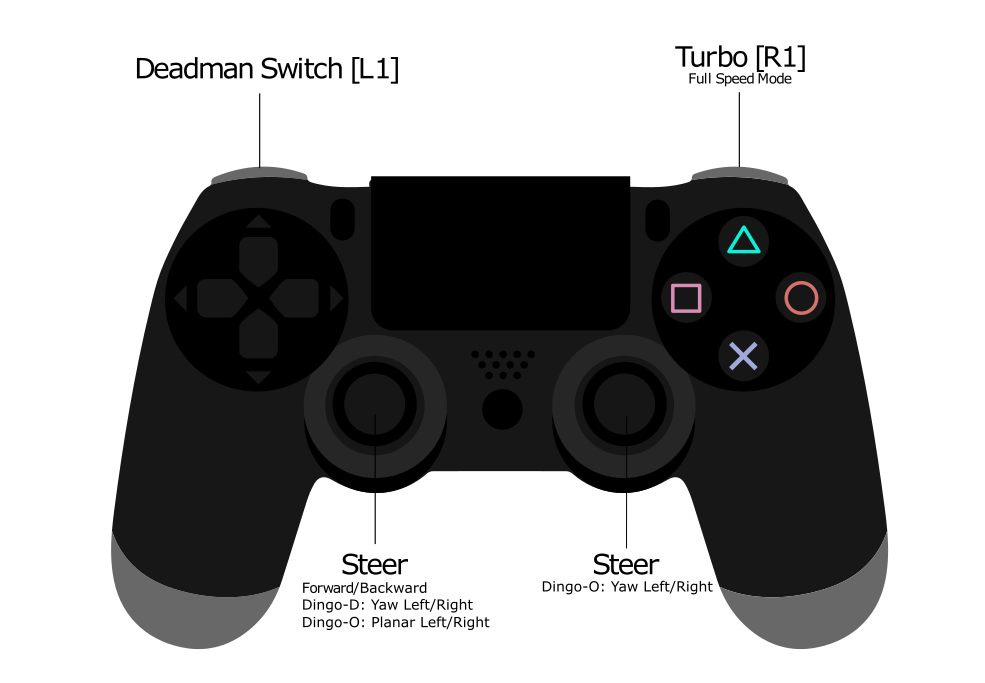
To teleoperate Dingo, first clear the motion-stop.
Then, power on the controller by pressing the PS button on the controller.
Once the blue LED on the top of the controller goes solid, you are paired and ready to drive.
Hold the L1 trigger button (deadman switch) and push the left thumbstick forward to drive the Dingo. For full speed mode, hold the R1 trigger. See the figure below for the Sony PS4 controls layout. If you are not seeing any action, refer to Support to get in touch with support.
Using ROS
Robot Operating System (ROS) is an extensible framework for controlling and working with robotic systems. Clearpath Robotics recommends using ROS with your robot. If this is your first time using ROS, it is strongly recommended to run through our series of ROS tutorials to learn the basics of ROS.
Battery Charging
- Dingo 1.0
- Dingo 1.5
For Dingo 1.0, when finished with the Dingo, press and release the power button ![]() to power it off.
Then remove the batteries for charging.
to power it off.
Then remove the batteries for charging.
Dingo's batteries are charged outside the Dingo using the charger(s) provided.
Alternatively, if you have multiple batteries, you can hot-swap them one at a time. The system will remain operational while hot-swapping as long as there is at least one battery in the system or the system is connected to shore power prior to removing the batteries. Note that plugging in shore power will engage a motion-stop and it is not possible to drive Dingo while connected to shore power.
The Sealed Lead-Acid batteries have overcurrent protection in the form of an ATO fuse. The lithium batteries include integrated protections against fault due to overcurrent, overdischarge, and short circuit. The batteries are rugged and designed for the demanding environments into which Dingo may be deployed.
For Dingo 1.5, to charge the batteries, simply connect the manual charger to the charge port on the front of the Dingo. Charging can take place while the unit is powered, or unpowered, or while the unit is connected to DC Shore Power. The charging current for the SLA system is 6A, and 7A for the LiFEPO4 system. Care must be taken when charging while the system is powered, as if the load/total current is higher than the supplied charge current the batteries will continue to drain. If the total system current is less than the charge current the batteries will charge, but at a reduced rate as the system will be using a portion of the charger current to maintain operation.
For multi-battery systems the charge current is distributed across the number of batteries present in the system, so charging time will increase appropriately. Care should be taken when removing or installing batteries. The batteries must be at the same charge level or voltage before connecting them together in the system. The easiest way to ensure this is to have an external charger, and by charging each battery individually with that charger to a full charge so all batteries are at the same charge level (or voltage). Once at the same level it is ok to connect them together in the unit. Failure to follow this procedure can result in battery/system damage and/or personal injury.
However, please take note of the following:
- SLA batteries must be charged while in a 0 to +45 ◦C range and discharged while in a -30 to +60 ◦C range.
- Lithium batteries must be charged while in a 0 to +50 ◦C range and discharged while in a -20 to +60 ◦C range.
- LiFEPO4 batteries must be charged within a 0 to +45 ⁰C range and discharged while in a -20 to +60 ⁰C range.
- Chargers must be placed on a hard surface, not on a carpet or other insulating device, as they can get hot during the bulk charging phase.
Please contact Clearpath Robotics for additional information about Dingo's batteries or for information about purchasing additional batteries.
Safety Considerations
Clearpath Robotics is committed to high standards of safety. Dingo contains several features to protect the safety of users and the integrity of the robot.
Dingo is a fast moving robotic platform. Please read the following notices carefully.
General Warnings
Dingo is a rugged and high-performance vehicle. For the safety of yourself and others, always conduct initial experiments and software development with the vehicle raised off the ground. Place a wooden crate, a set of sawhorses, a sturdy storage tub, or any other solid flat structure having a height greater than 150 mm (6 inches) under Dingo to keep the wheels clear of the ground ("up on blocks").
When starting out, favour slower wheel speeds. Dingo's control loops can accurately maintain velocities as low as 0.1 m/s. Operating at such speeds will give you more time to react if things don't go quite as you expect.
Motion Stop Buttons
The Motion Stop button ![]() is located on the HMI Panel at the back of Dingo.
To engage Stop Mode, press the Motion Stop button once; you should see that the green LED by the Motion Stop button is flashing and that all four corner LEDs are flashing red.
To disengage Stop Mode, press the Motion Stop button again; all LEDs should return to their original values.
is located on the HMI Panel at the back of Dingo.
To engage Stop Mode, press the Motion Stop button once; you should see that the green LED by the Motion Stop button is flashing and that all four corner LEDs are flashing red.
To disengage Stop Mode, press the Motion Stop button again; all LEDs should return to their original values.
When in Stop Mode, the Dingo will not drive. The commands received while in Stop Mode are not buffered; Dingo will always act on the latest commands received. This means that if the commands are stopped before the Motion Stop button is pressed to disengage Stop Mode, the Dingo will not move. If the commands are continued, Dingo will move at the speed commanded once the Motion Stop button is pressed to disengage Stop Mode.
Ensure that the Motion Stop button is accessible at all times. Avoid mounting payloads that extend over the rear of Dingo and would block access to the Motion Stop button.
Note that the Dingo MCU board does provide a breakout to allow an external motion-stop button/switch to be integrated by the end user, which could be used to engage/disengage Stop Mode. See Optional External Motion Stop for details on adding an external motion-stop button/switch.
Electrical System
Dingo is powered by batteries capable of delivering over 2000W for short durations. This gives Dingo's motors their great performance; however, it is also enough power to cause severe bodily harm. Always use caution when operating Dingo to avoid personal injury or property damage. To ensure safety, please observe the following precautions:
- Do not tamper with the battery terminals or wiring.
- Do not tamper with the fuses, except to check and change the fuses.
- Always replace fuses with the same type and rating to ensure continued protection against risk of fires.
- Consult Clearpath Robotics support if you need to service the batteries.
- Do not lay tools or other objects on top of the batteries.
- Charge the battery only with the charger provided by Clearpath Robotics.
- Please dispose of the batteries properly or return them to Clearpath Robotics to do so.
Lifting and Transport
- Ensure that Dingo's Stop Mode is engaged when transporting short distances and powered off when transporting longer distances.
- Do not push the robot at more than 0.5 m/s (1.6 ft/s) or damage to the motor controls may occur.
Performance Considerations
Included in Dingo are native software checks and limits to protect the robot.
However, it is recommended to monitor the system's status during usage with the /status and /diagnostics topics.
These topics provide useful information regarding voltages, currents, temperatures and general health of the system.
Recommended Safe Work Procedures
Clearpath Robotics recommends the following procedures be followed to reduce the likelihood of harm.
- Maintain a safe distance of at least 10 m from the robot whenever possible.
- Never assume that the robot can be reliably stopped on command.
- Assert a stop using the remote stop device (if present) before approaching the robot.
- Never place the remote stop device (if present) on or inside the robot.
- Always be vigilant around the robot, even when a stop is asserted.
- Perform no maintenance or troubleshooting on the robot without training and familiarization.
- Follow electrical safety best practices when working with electrical systems and components.
- Disconnect battery using main disconnect of the robot before working inside robot.
- Wear personal protective equipment including high-visibility clothing, head and eye protection while operating, observing or working on the robot.
- Never climb on or ride the robot.
- Never lie on the ground under or near the robot.
- Avoid operating the robot on slopes and grades.
- Never stand downhill of the robot.
- Operate the robot at the lowest speed possible.
- Never attempt to defeat a safety function for any reason.
- Chock the robot's wheels when the robot will be stationary for more than a few seconds.
- Never work on the robot while it is on a slope.
- Replace fuses only with identical product from specified manufacturer.
- Discontinue use and contact Clearpath Robotics support at the first sign of strange robot behaviour.
- Keep tools and loose parts away from electrical components and out of the robot's bays.
- Check the functionality of stop systems on a regular basis, including before and after each use.
Support
Clearpath is committed to your success. Please get in touch with us and we will do our best to get you rolling again quickly: support@clearpathrobotics.com.
To get in touch with a salesperson regarding Clearpath Robotics products, please email research-sales@clearpathrobotics.com.
If you have an issue that is specifically about ROS and is something which may be of interest to the broader community, consider asking it on Robotics Stack Exchange. If you do not get a satisfactory response, please ping us and include a link to your question as posted there. If appropriate, we will answer on Robotics Stack Exchange for the benefit of the community.