Husky A300 Maintenance
Preventative Maintenance
DANGER
Always follow the proper Lock-Out Tag-Out Procedure for Husky A300 when completing inspections or maintenance.
Access to live voltage inside Husky A300 may occur if the proper Lock-Out Tag-Out procedure is not followed. This may result in electric shock.
CAUTION
Always follow safe handling procedures when performing maintenance.
Sharp edges may exist inside the robot.
CAUTION
Always follow facility guidelines to clean up fluid spills.
These may present a slip hazard.
Weekly Prevenative Maintenance
Perform the following tasks at least once every week.
Circle Check
Perform a circle check around Husky daily to ensure no damage has occurred since its last usage. During this visual inspection, ensure the robot is turned on and verify that:
- The Status Lights are functioning correctly by pressing an Emergency Stop button and checking for the Emergency Stop light pattern.
- The robot was not damaged during the last operation.
Husky is an all-terrain IP54-rated robot, but it is not waterproof. Care should be taken that no part of the main chassis is ever submerged in water. When the chassis becomes wet or dirty, wipe it down with a damp cloth and dry with a towel.
If water is suspected to have entered the Husky chassis, power off the robot, open the top plate to ensure that any water has drained out through the drain plug, and allow Husky to dry fully (for a minimum of 24 hours) prior to putting it back into service.
Clean or Replace Air Filter
The air filter is used to prevent dirt and dust from entering the robot at the front air intake. It must be cleaned or replaced on a regular basis. High-dust environments will require more frequenct maintenance.
The air filter is foam and can be washed, then reused.
Procedure:
- Remove the front Livery panel by loosening the quarter-turn latches
and lifting the panel up. Be careful not to damage the Emergency Stop
Button while removing the panel.
- Remove the air filter.
- Wash the filter with water and allow it to dry fully. (Alternatively, replace with a new filter.)
- Install the clean filter.
- Replace the front livery panel by aligning the pins and tighten the quarter-turn latches.
Battery Cell Balancing (Quick)
Husky is powered by LiFePO4 batteries. The function and health of these batteries is monitored by a Battery Management Unit (BMU) which is internal to the battery pack itself.
Over the operating life of Husky, the State of Charge (SoC) of the batteries may start being misreported accompanied by a higher voltage difference between the batteries' cells. Typically battery cells should be within a range of 50 mV; if not, Husky's batteries may suddenly drop in SoC while operating or the Husky may unexpectedly shut off. To resolve this issue, it is required to perform regular cell balancing of the battery and BMU.
A "quick" cell balancing should be performed at least once each week.
Procedure:
- Power off the robot.
- Place the robot on a level surface.
- Connect the manual charger.
- Let the batteries charge for at least four hours.
AMP Sensor Cleaning
The AMP variant of Husky is equipped with additional sensors that should be inspected at least weekly (more often in high dust/dirt environments) and cleaned as needed.
LiDAR Lens Cleaning
- Inspect LiDAR lens with a flashlight for any dust and/or debris.
- Using the Lens Cleaning Wipes (Clearpath p/n 015591), clear the LiDAR of any dust/debris.
CAUTION
Do not use abrasive items or solvents on the LiDAR assembly, as this will damage the LiDAR. Used and dirty cleaning cloths or wipes will scratch the window over time. The LiDAR window is a wear item but proper care and cleaning can significantly extend its life.
Camera Cleaning (clean with microfiber cloth or CPR-approved cleaning wipe if dirty)
- Visually inspect the camera lenses and confirm there is no dust or debris on them.
- If necessary, carefully clean the lenses with a microfiber cloth or a Clearpath Robotics-approved cleaning wipe.
CAUTION
Do not apply excessive pressure to the camera lenses.
Monthly Preventative Maintenance
Perform the following tasks once every month.
Battery Cell Balancing (Full)
Refer to the notes above regarding the weekly "quick" cell balancing. In a addition, a full balance of 24+ hours is recommended at least once per month.
Procedure:
- Power off the robot.
- Place the robot on a level surface.
- Connect the manual charger.
- Let the batteries charge for at least 24 hours.
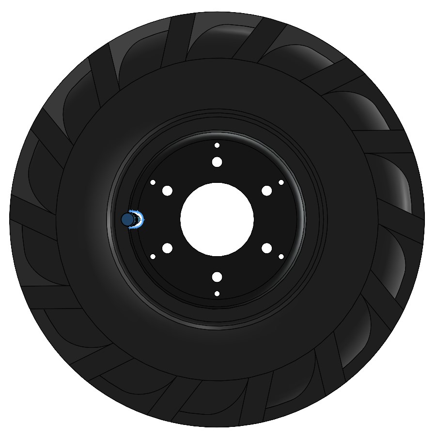
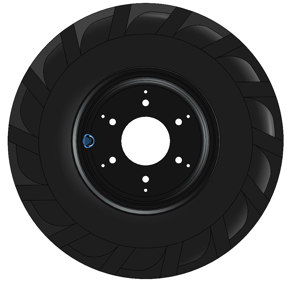
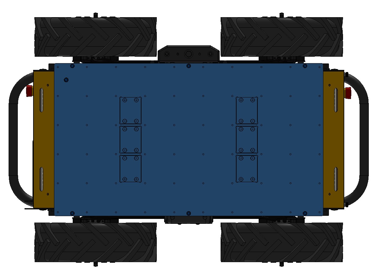
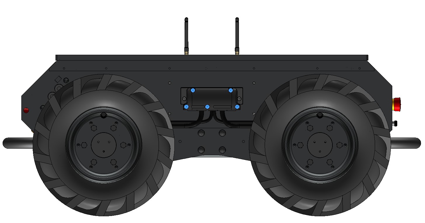
Tire Inspection
Tire pressure may change with temperature and should be checked monthly with a pressure gauge. Inspecting tires, releasing pressure, and inflating tires are completed through the tire's inflation stem. Tire pressure should not exceed 137 kPa (20 psi), and lower pressure may be desired based on terrain requirements. A monthly visual inspection of the tire treads is also recommended. Replacement tires and tubes assemblies can be purchased from Clearpath Robotics and can be installed by the user.
Husky's wheels can handle a range of different terrains, but work best when inflated to the proper pressure. Lower tire pressures, for example 68.5 kPa (10 psi), ensure better traction in rough and varied terrain, where rocks or other obstacles may be encountered. This has the adverse effect of lowering drivetrain efficiency and decreasing battery charge, so high pressures up to a maximum of 137 kPa (20 psi) should be used when driving on flat surfaces.
Lower tire pressuses also reduce the effective diameter of the wheel, and will impact your odometry readings. Odometry is calculated using the average diameter of a tire inflated to 137 kPa (20 psi).
Tire inspection procedure:
- Power off the robot.
- Place the robot on a level surface.
- Using a tire pressure gauge, check the pressure on each tire to confirm it is 68.5 - 137 kPa (10 - 20 psi). Add or remove air as needed to ensure each tire is in the proper range. If leaks persist, change the tire tube.
- One wheel at a time, slowly roll Husky through full wheel revolution while inspecting the tire for excessive wear, cuts, or punctures. If any damage is detected, replace the tire.
Drivetrain Inspection
It is recommended that an auditory inspection of the robot drivetrain be performed once per month. Take note of any clicking, grinding or irregular skipping sounds while the robot is moving. Note that some clicking in the gearheads is normal during stops and starts, due to backlash between the gears.
36-Month Preventative Maintenance
Perform the following tasks once every thirty-six months.
Battery Health Check
Husky's batteries are expected to last for at least 36 months of continuous operation. The actual lifetime experienced will vary greatly depending on the usage and operating environment. Contact Support for an in-depth assessment of the battery's health if you have any concerns.
Hardware Maintenance
Common Replacement Items
This does not cover the full bill-of-materials for your robot. These items are things we consider critical, so you may want to keep spares on hand. You can get any replacement part by contacting <support@clearpathrobotics.com>, including parts not listed here.
| Description | CPR Item | Manufacturer | Manufacturer Item | Distributor | Distributor Item |
|---|---|---|---|---|---|
| Tire | 000269 | Carlisle | 5100201 | - | - |
| Tire's inner tube | 000435 | Carlisle | 323790 | - | - |
| Battery | 025047 | Clearpath Robotics | - | - | - |
| Battery Charger | 032729 | Clearpath Robotics | - | - | - |
| Air filter | 032403 | Clearpath Robotics | - | - | - |
| Main PCBA | 030449 | Clearpath Robotics | - | - | - |
| BLDC PCBA | 030377 | Clearpath Robotics | - | - | - |
| Common Core PCBA | 030446 | Clearpath Robotics | - | - | - |
| 12 V DC/DC PCBA | 030430 | Clearpath Robotics | - | - | - |
| 24 V DC/DC PCBA | 030433 | Clearpath Robotics | - | - | - |
| Motor | 031514 | Clearpath Robotics | - | - | - |
See also the common integration parts for cable ingress and breakout connectors.
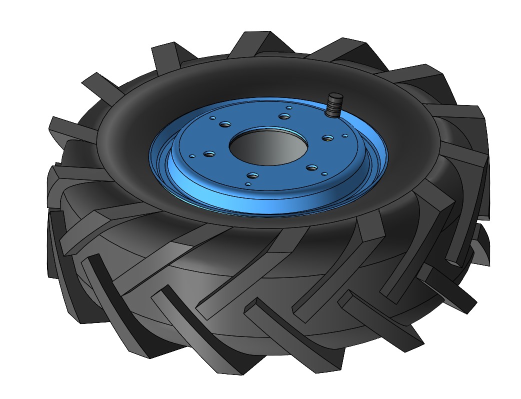
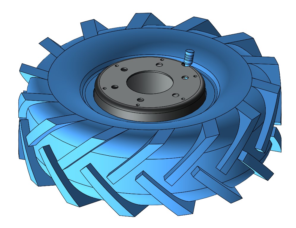
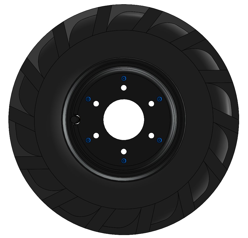
Replacing Tire or Inner Tube
WARNING
Place the robot up on blocks prior to replacing the tire or inner tube.
Failure to support the robot prior to removing the wheel could cause the robot to tip over.
Procedure:
-
Follow the Lock-Out Tag-Out procedure.
-
Remove the six M8 screws holding the wheel to the motor.
-
Deflate the tire.
-
Remove the six M4 screws that hold the split rim together.

-
Remove the outer wheel rim.
-
Remove the tire and tube from the inner rim.
-
Replace the tire and/or tube as needed with new parts. Ensure that the tube is installed in the tire and inflated only far enough that it takes its shape. Inflating further will make reassembly difficult.
-
Place the tire (with tube) onto to inner rim, aligning the valve stem with the notch in the rim.
-
Place the outer rim on top, aligning the value stem with the notch in the rim.
-
Reinstall the six M4 screws, tightening them in a star pattern to 2 Nm.
noteIt may be necessary to use three longer M4 screws on a temporary basis to help pull the inner and outer rims together and ensure alignment, allowing the first three standard M4 screws to be installed. Then, the temporary M4 screws can be removed and the standard ones installed. As you tighten the screws, ensure that the valve stem is not being pinched.
-
Inflate the tire to 20 psi.
-
Place the wheel on the motor and reinstall the six M8 screws, tightening them in a star pattern to 22 Nm.
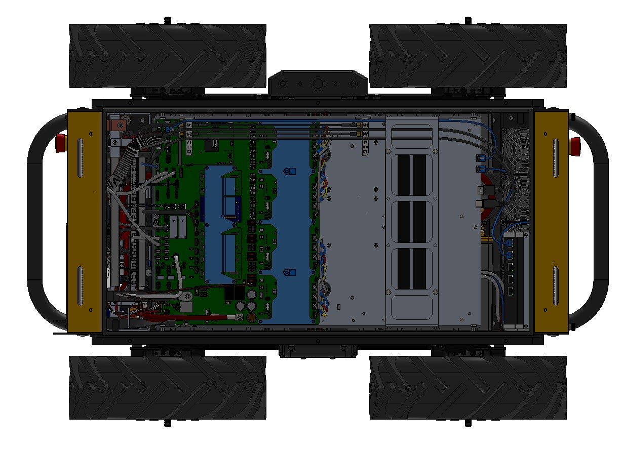
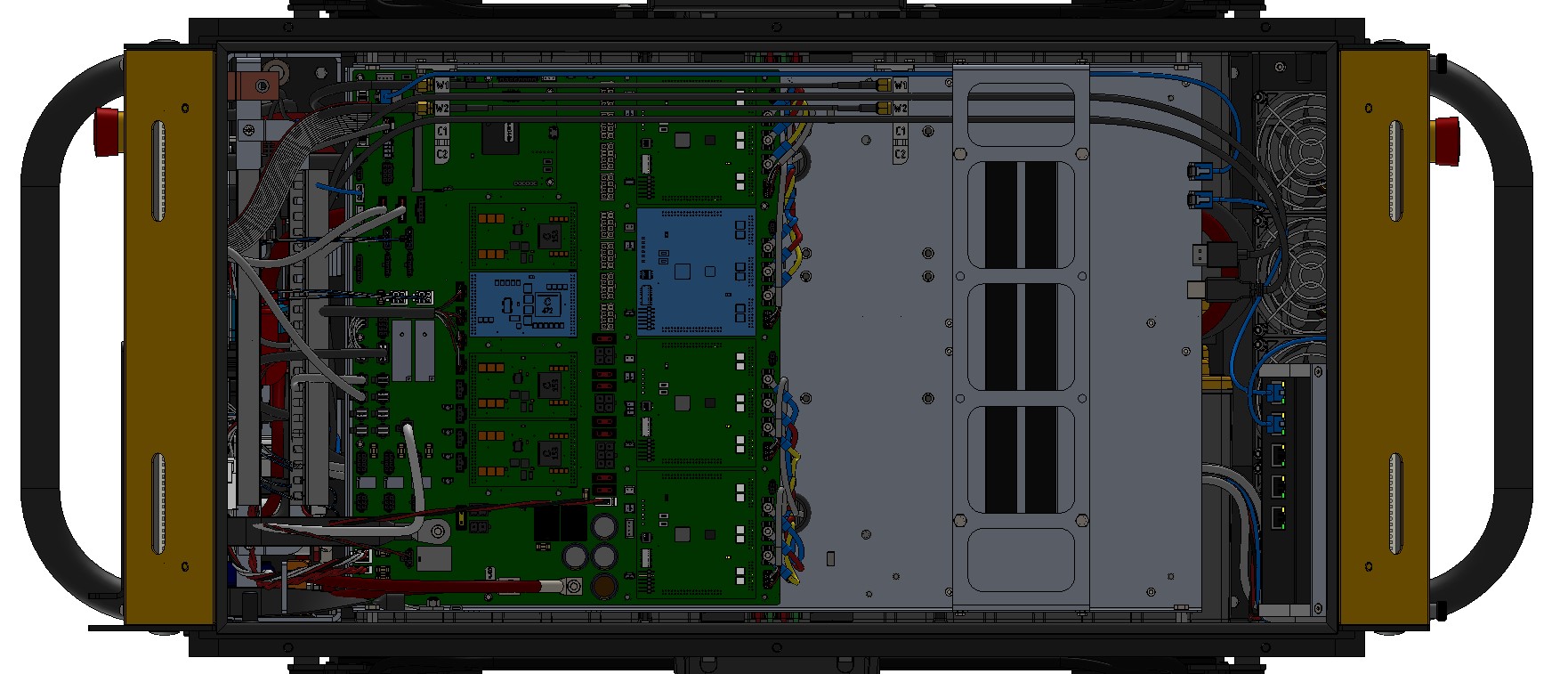
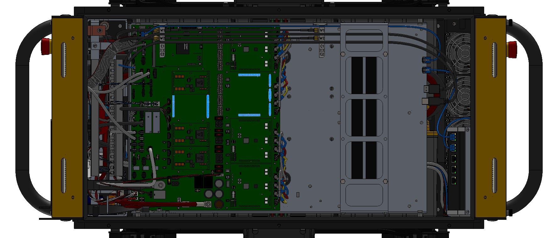
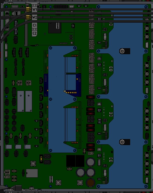
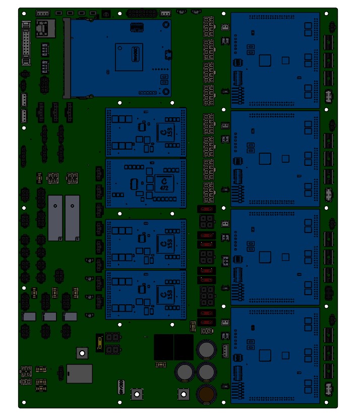
Replacing Circuit Boards
Husky contains several circuit boards (PCBAs). If a failure occurs, there is normally only one board that needs to be replaced.
CAUTION
Circuit boards are sensitive components and can be damaged easily through electrostatic discharge (ESD). Be sure to follow proper ESD protection measures prior to handling any circuit boards.
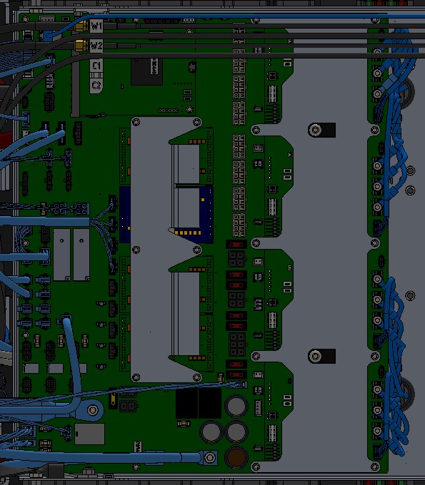
Procedure for replacing the DC/DC and BLDC circuit boards:
- Follow the Lock-Out Tag-Out procedure.
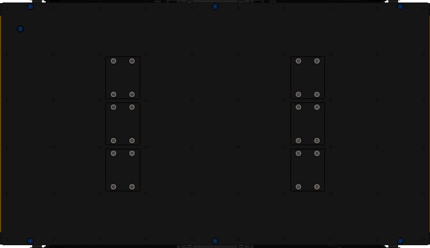
- Remove the seven screws that fasten the Top Plate to the chassis and remove the Top Plate.
- Remove the cable brush holder.

- Remove the heat shield covering the DC/DC and/or BLDC circuit boards.
- Remove the failing circuit board by gently lifting the board up.
- Install the new circuit board by aligning the connector and gently sliding it into place.
- Reinstall the heat shields.
- Reinstall the cable brush holder.
- Put the Top Plate back in place and finger tighten the seven screws that were removed in Step 2.
Note that the screw with the sealing washer goes in the inner location and the remaining
six screws are installed at the perimeter. Tighten all seven screws to 3 Nm.
Procedure for replacing the Common Core circuit board:
- Follow the Lock-Out Tag-Out procedure.
- Remove the seven screws that fasten the Top Plate to the chassis and remove the Top Plate.
- Remove the failing circuit board by removing the two retaining screws, pushing out on the retaining
clips, and gently pulling the board out horizontally.
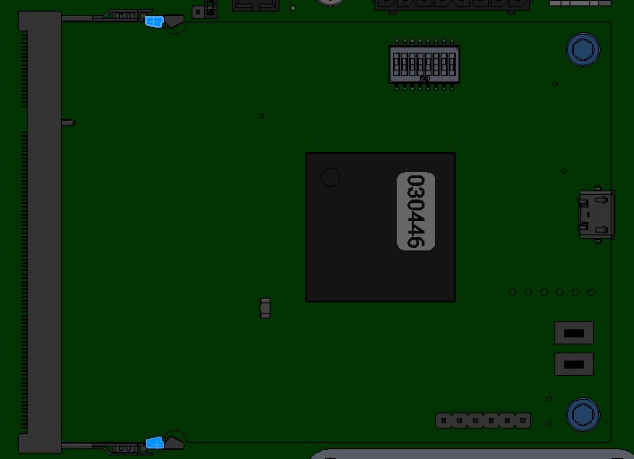
- Install the new circuit board by gently sliding it into place horizontally, ensure that the retaining clips are secured, and that the two screws have been installed.
- Put the Top Plate back in place and finger tighten the seven screws that were removed in Step 2.
Note that the screw with the sealing washer goes in the inner location and the remaining
six screws are installed at the perimeter. Tighten all seven screws to 3 Nm.
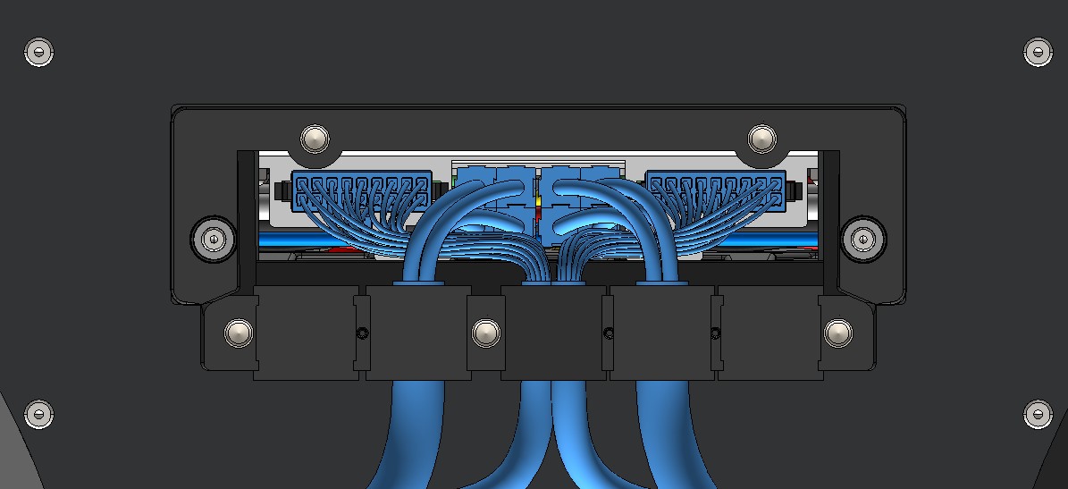
Procedure for replacing the Main circuit board:
- Follow the Lock-Out Tag-Out procedure.
- Remove the seven screws that fasten the Top Plate to the chassis and remove the Top Plate.
- Disconnect all cables from the Main circuit board.
- Remove the failing circuit board by removing the retaining screws and then lifting out the board.
- Place the old and new Main circuit boards on an ESD mat.
- Move the DC/DC, BLDC, and Common Core circuit boards from the old to the new Main circuit board
by following the procedures above.
- Install the new Main circuit board tighten the retaining screws to 1 Nm.
- Reconnect all cables, noting that the labels on the cables should match those on the board.
- Put the Top Plate back in place and finger tighten the seven screws that were removed in Step 2.
Note that the screw with the sealing washer goes in the inner location and the remaining
six screws are installed at the perimeter. Tighten all seven screws to 3 Nm.
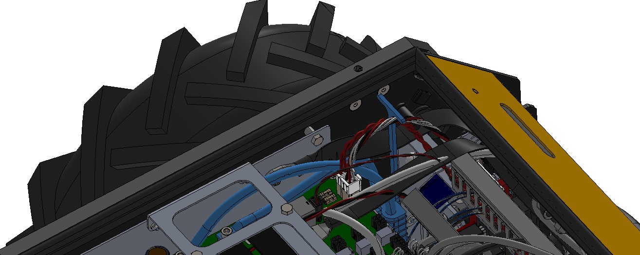
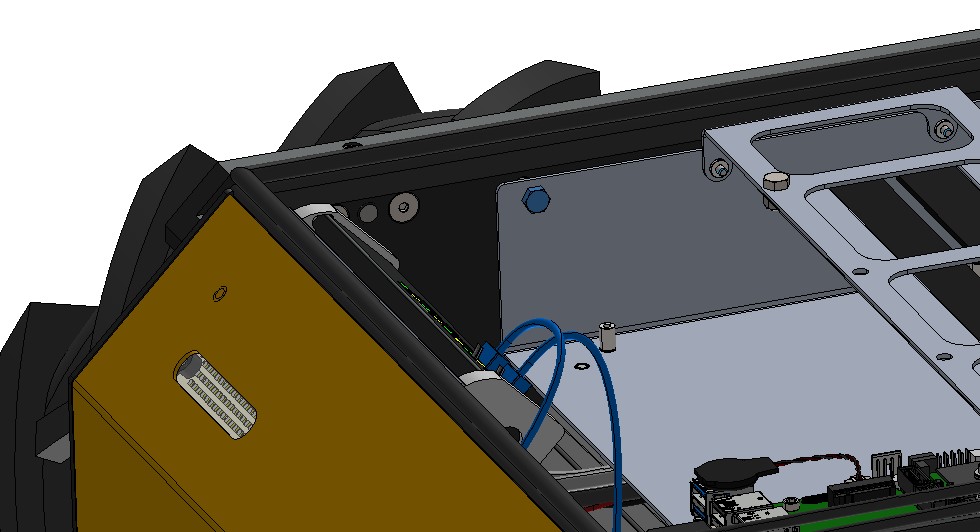
Replacing the Computer
CAUTION
Circuit boards are sensitive components and can be damaged easily through electrostatic discharge (ESD). Be sure to follow proper ESD protection measures prior to handling any circuit boards.
If the existing computer is still operational, a backup of any important data should be made prior to its replacement.
Procedure:
- Follow the Lock-Out Tag-Out procedure.
- Remove the seven screws that fasten the Top Plate to the chassis and remove the Top Plate.
- Disconnect all cables from the computer.
- Remove the computer by removing the four retaining screws and lifting it
out of the robot.
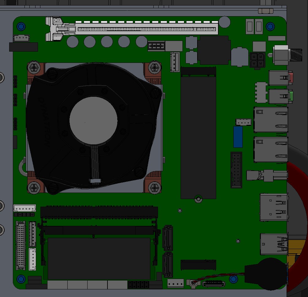
- Install the new computer and tighten the four retaining screws to 1 Nm.
- Reconnect all cables.
- Put the Top Plate back in place and finger tighten the seven screws that were removed in Step 2.
Note that the screw with the sealing washer goes in the inner location and the remaining
six screws are installed at the perimeter. Tighten all seven screws to 3 Nm.
- As needed, reinstall any custom configuration that has been backed up.
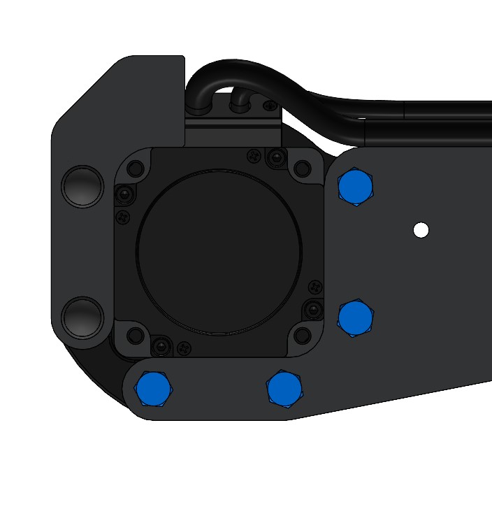
Replacing Motors
Procedure:
- Follow the Lock-Out Tag-Out procedure.
- Remove the cable gland bracket on the side of the robot with the motor being
replaced by removing five screws.
- Disconnect the both sets of motor power and cables from the chassis on the
side of the robot with the motor being replaced.
- Remove the suspension beam from the chassis by removing the four nuts
and washers.
- Remove the wheel from the motor (see above).
- Remove the failing motor from the suspension beam by removing the four
M8 screws.
- Mount the new motor on the suspension beam and tighten the four screws to 20 Nm.
- Re-install the wheel onto the motor (see above).
- Mount the suspension beam on the chassis, install the four washers, and tighten the four nuts to 30 Nm. (Do not overtighten!)
- Reconnect both sets of motor power and cables.
- Install the cable gland bracket and tighten the five screws to 1 Nm.
Replacing Batteries
DANGER
Battery terminals and connected cables / busbars may be live. Follow proper safety procedures when performing any maintenance on the batteries.
Only trained personnel authorised by Clearpath Robotics shall perform maintenance on the batteries.
Ensure proper personal protective equipment is used when performing battery maintenance.
- Follow the Lock-Out Tag-Out procedure.
- Remove the cable gland brackets on both sides of the robot by removing five screws on each.
- Disconnect all motor power and encoder cables from the chassis.
- Remove the seven screws that fasten the Top Plate to the chassis and remove the Top Plate.
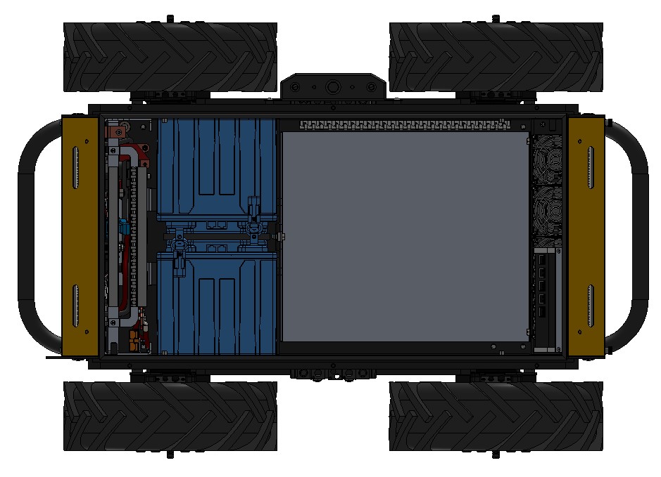
- Locate the V+ connector and pull the handle to disconnect it.
- Disconnect all cables at the front of the electronics tray.

- Remove two screws at the front of the electronics tray used to fasten the
tray to the side of the robot.
- Tilt the electronics tray up to expose the batteries.
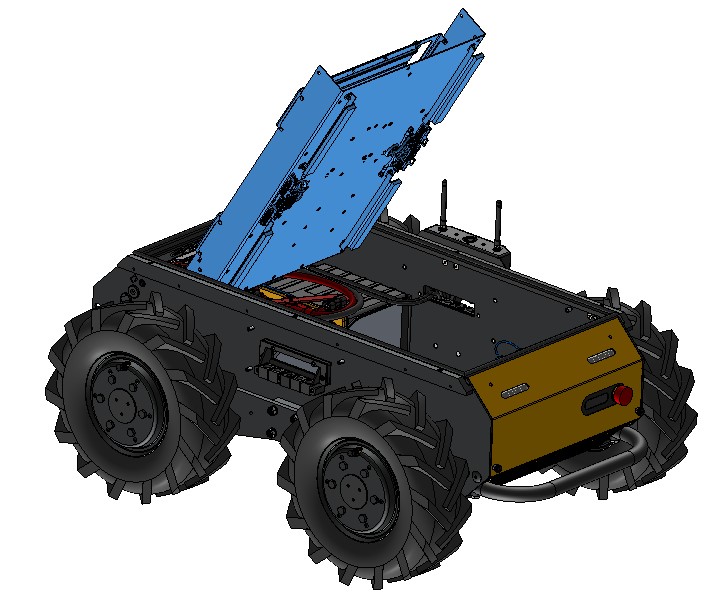
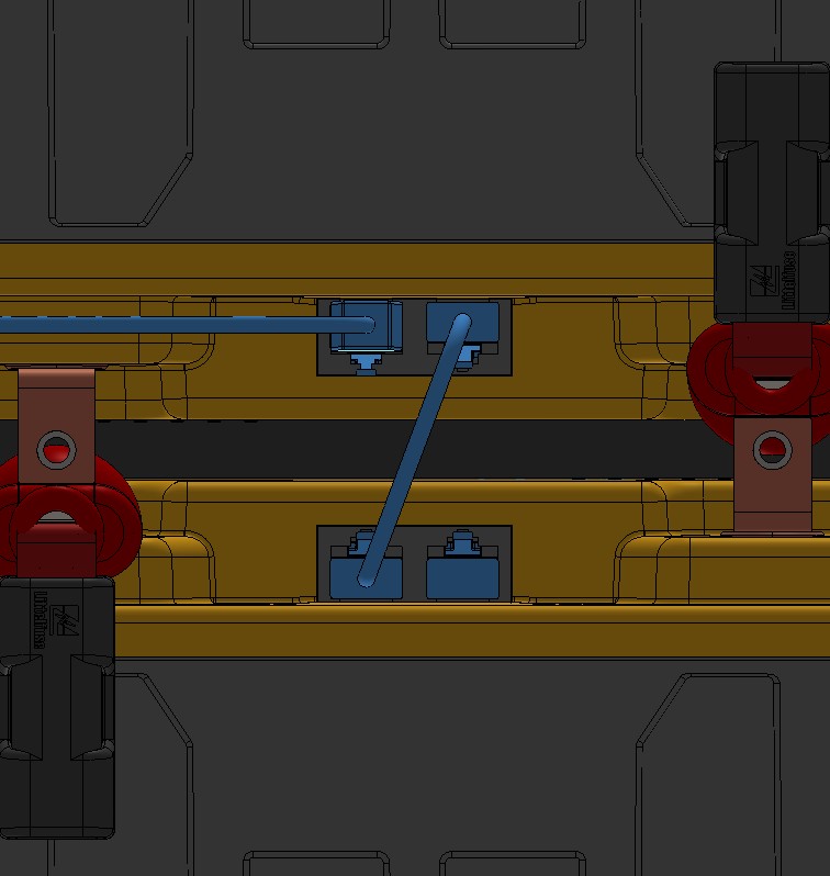
- Disconnect and remove the positive battery busbar by removing the
two fuse covers, disconnecting the terminals, and lifting up the busbar.
- Disconnect and remove the negative battery busbar by removing the
two screws. This also disconnects the battery ground cable.
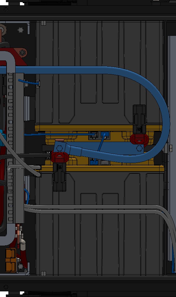
- Disconnect any CAN bus cables (RJ45 connectors) at the batteries.
- Remove the battery to be replaced and the battery to which its
terminals were facing. Note that batteries are installed in pairs.
- Move the terminal connectors from the old battery to the new battery.
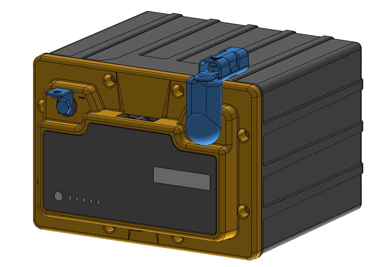
- Align the pair of batteries so that their terminals are facing and slide the pair of batteries into the robot. A temporary locking strap to hold the two batteries together may make this step easier.
- Reconnect the CAN bus cables (RJ45 connectors).
- Re-install the negative battery busbar and ground cable. Tighten the two screws to 5 Nm.
- Re-install the positive battery busbar by placing it across the two fuses and tightening the two nuts to 3 Nm.
- Replace the two fuse covers.
- Tilt the electronics tray back into position and tighten the two screws used to fasten the tray to the side of the robot to 3 Nm.
- Reconnect all cables at the front of the electronics tray.
- Locate the V+ connector handle and re-install the connector.
- Put the Top Plate back in place and finger tighten the seven screws that were removed in Step 2.
Note that the screw with the sealing washer goes in the inner location and the remaining
six screws are installed at the perimeter. Tighten all seven screws to 3 Nm.
- Reconnect all motor power and encoder cables on the chassis.
- Re-install the cable gland brackets on both siders of the robot, tightening the five screws on each to 1 Nm.
Software Maintenance
Getting New Packages
If you are upgrading your robot from an older version of ROS, please refer to our upgrade instructions for upgrading to Melodic, Noetic and ROS 2 Humble.
Clearpath Robotics robots are always being improved, both its own software and the many community ROS packages upon which it depends!
You can use the apt package management system to receive new versions all software running on the platform.
Each robot leaves the factory already configured to pull packages from http://packages.ros.org as well as http://packages.clearpathrobotics.com. To update your package and download new package versions, simply run:
sudo apt-get update
sudo apt-get dist-upgrade
MCU Firmware Update
Customer updates of Husky firmware are not supported at this time. Contact Support if Husky firmware updates are needed.
Motor Controller Firmware Update
Customer updates of Husky firmware are not supported at this time. Contact Support if Husky firmware updates are needed.
Support
Clearpath is committed to your success. Please get in touch with us and we will do our best to get you rolling again quickly: <support@clearpathrobotics.com>.
To get in touch with a salesperson regarding Clearpath Robotics products, please email <research-sales@clearpathrobotics.com>.
If you have an issue that is specifically about ROS and is something which may be of interest to the broader community, consider asking it on Robotics Stack Exchange. If you do not get a satisfactory response, please ping us and include a link to your question as posted there. If appropriate, we will answer on Robotics Stack Exchange for the benefit of the community.