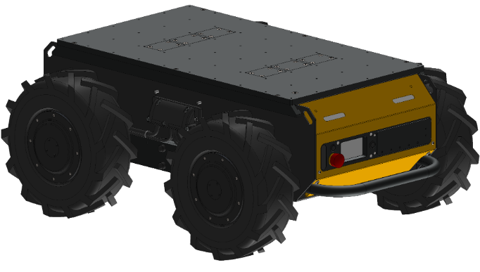
Husky A300 Maintenance
WARNING
Always follow the proper Lock-Out Tag-Out Procedure for Husky A300 when completing inspections or maintenance.
Access to live voltage inside Husky A300 may occur if the proper Lock-Out Tag-Out procedure is not followed. This may result in electric shock.
CAUTION
Always follow safe handling procedures when performing maintenance.
Sharp edges may exist inside the robot.
CAUTION
Always follow facility guidelines to clean up fluid spills.
These may present a slip hazard.
Maintenance Safety
Lockout Tagout
Lockout procedures remove potential energy from machines as we perform maintenance. This reduces risk of harm while performing maintenance. The Husky's main source of potential energy is the batteries. We cannot completely discharge these batteries without damaging them, but we can disconnect them from all the robot's electronics.
To disconnect the batteries, and lockout the machine:
- If applicable; move the Husky away from its Wireless Charger.
- Open the Husky's Rear Charge Port Door.
- Disconnect the Manual Charger.
- Flip the Circuit Breaker to the OFF position.
- Confirm that the robot will not turn on, by pressing and holding the ON-OFF button for 0.5 seconds.
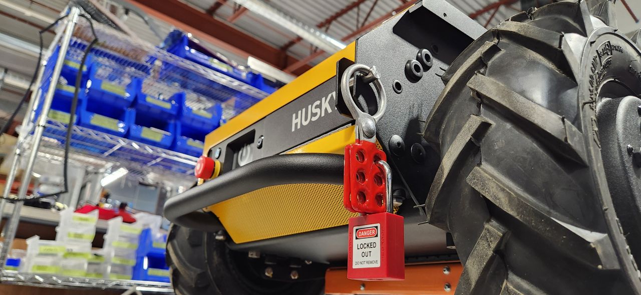
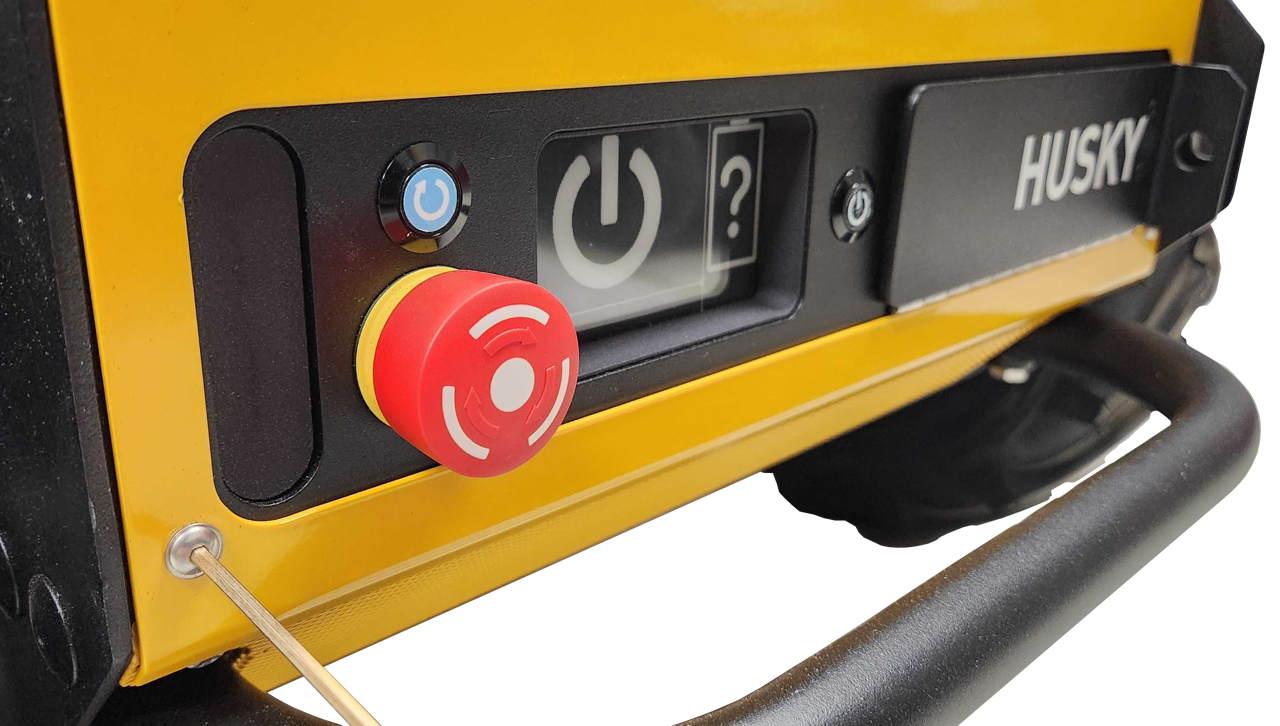
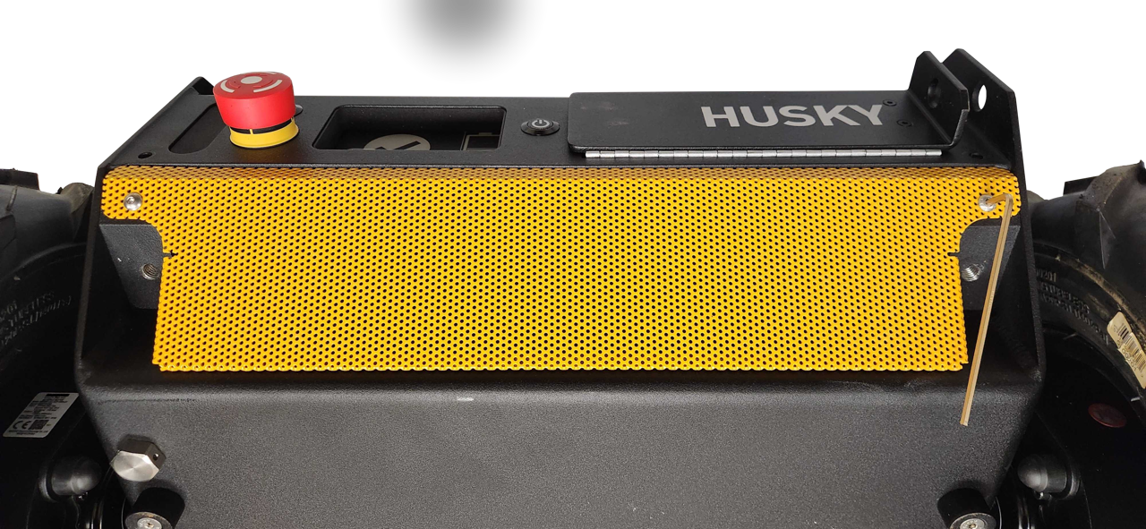
Now that you have isolated the batteries; you can lockout the robot. We do this by closing the Rear Charge Port Door, and then locking it to the robot's chassis.
The lockout pin and scissors shown in the image are not included with a standard Husky order. Any pin or hasp that prevents the Rear Charge Port Door from opening should be acceptable.
If you want the same hardware shown in this image, contact Clearpath's Support Team, and ask about the Lockout Kit—032200.
Follow the guidance below while performing maintenance to ensure that the system is in a safe state following any maintenance work on the robot.
- Clean up all tools and ensure that no tools or installation materials have been left inside the robot.
- Ensure that all cables have been tightened to the specified torque values and that there are no loose or unconnected cables.
- Reinstall any fuse covers that were removed.
- Restore all terminal boots to their original position prior to maintenance.
Once all parts have been reinstalled and maintenance is completed, perform the following system checks:
- Power on the robot.
- Place the robot up on blocks and confirm that each source of an emergency stop can be used to trigger the emergency stop condition by:
- confirming that the joystick can be used to make the wheels spin
- engaging the stop condition
- confirming that the corner lights go into a flashing red light pattern
- confirming that the joystick can no longer make the wheels spin
- disengaging the stop condition
- pressing the restart button
- confirming that the corner lights return to the normal driving pattern
- confirming that the joystick can be used to make the wheels spin again.
notePerform this check of emergency stop functionality individually for each of:
- Front Emergency Stop Button
- Rear Emergency Stop Button
- Rear Charge Port Door
- Wireless Emergency Stop Button (if present)
- Additional Emergency Stop Buttons (if present)
- Connect the manual charger and charge the robot for at least 5 minutes. Confirm that the state of charge is increasing and that there are no unexpected sounds or smells.
- With the robot in an open area at least 10 m in diameter and away from other people, connect the joystick and drive the robot for at least 30 seconds to confirm it is performing as expected.
Weekly Preventative Maintenance
Perform the following tasks at least once every week.
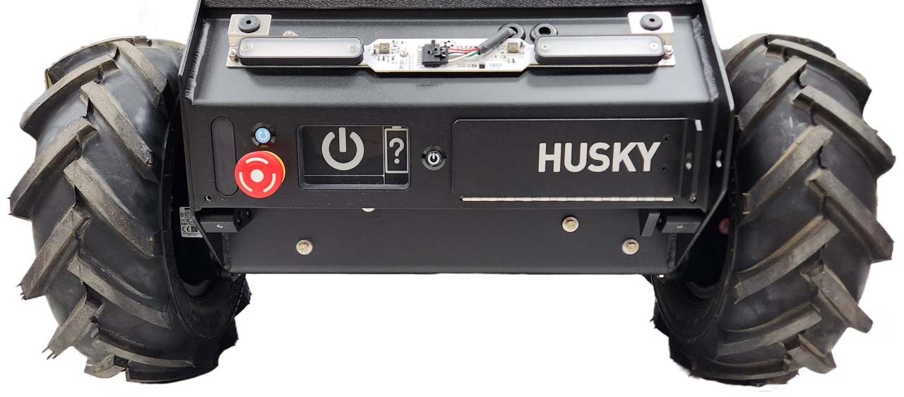
Circle Check
Perform a circle check around Husky daily to ensure no damage has occurred since its last usage. During this visual inspection, ensure the robot is turned on and verify that:
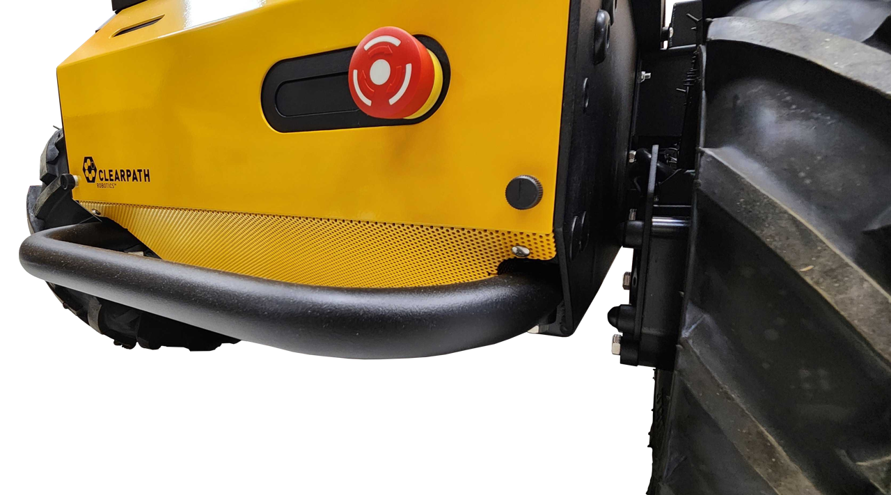
- The Status Lights are functioning correctly by pressing an Emergency Stop button and checking for the Emergency Stop light pattern.
- The robot was not damaged during the last operation.
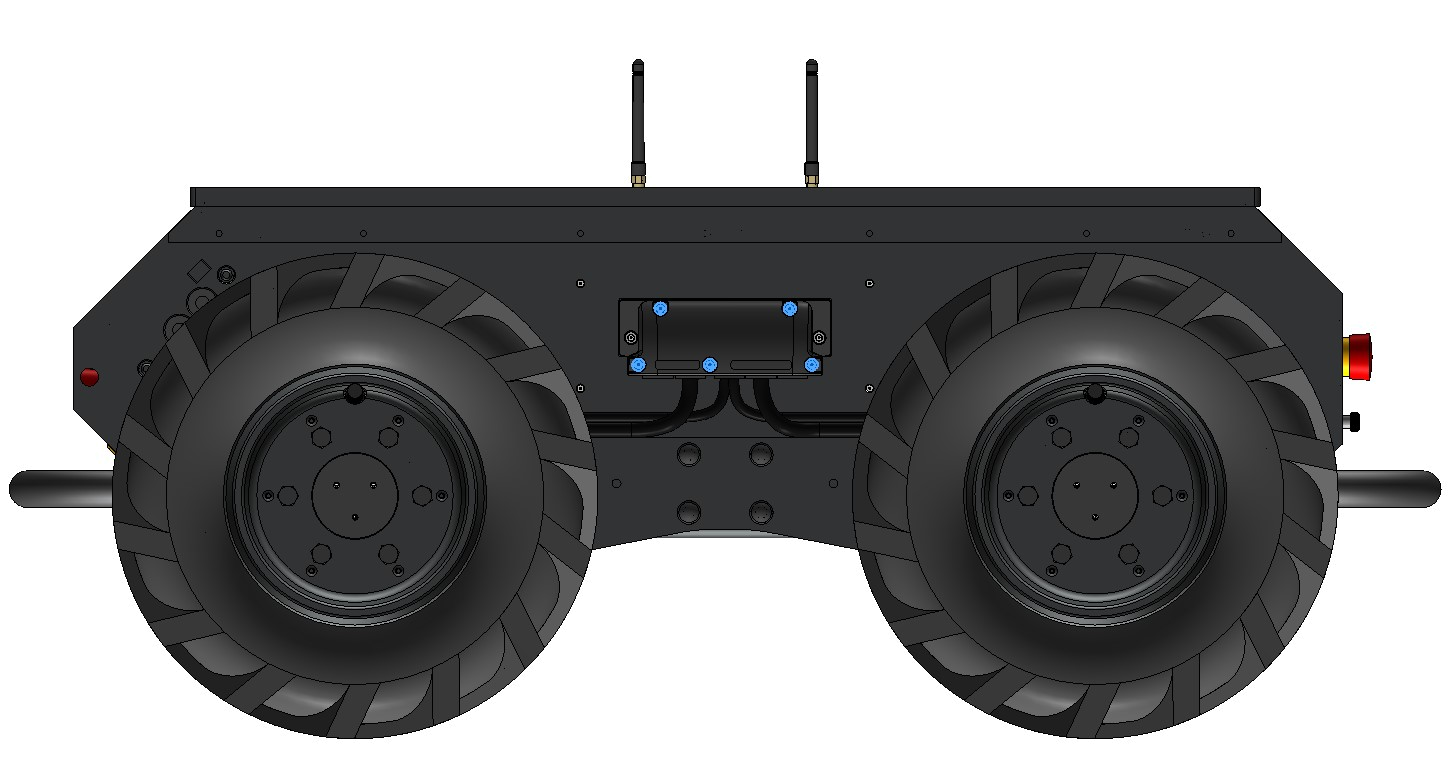
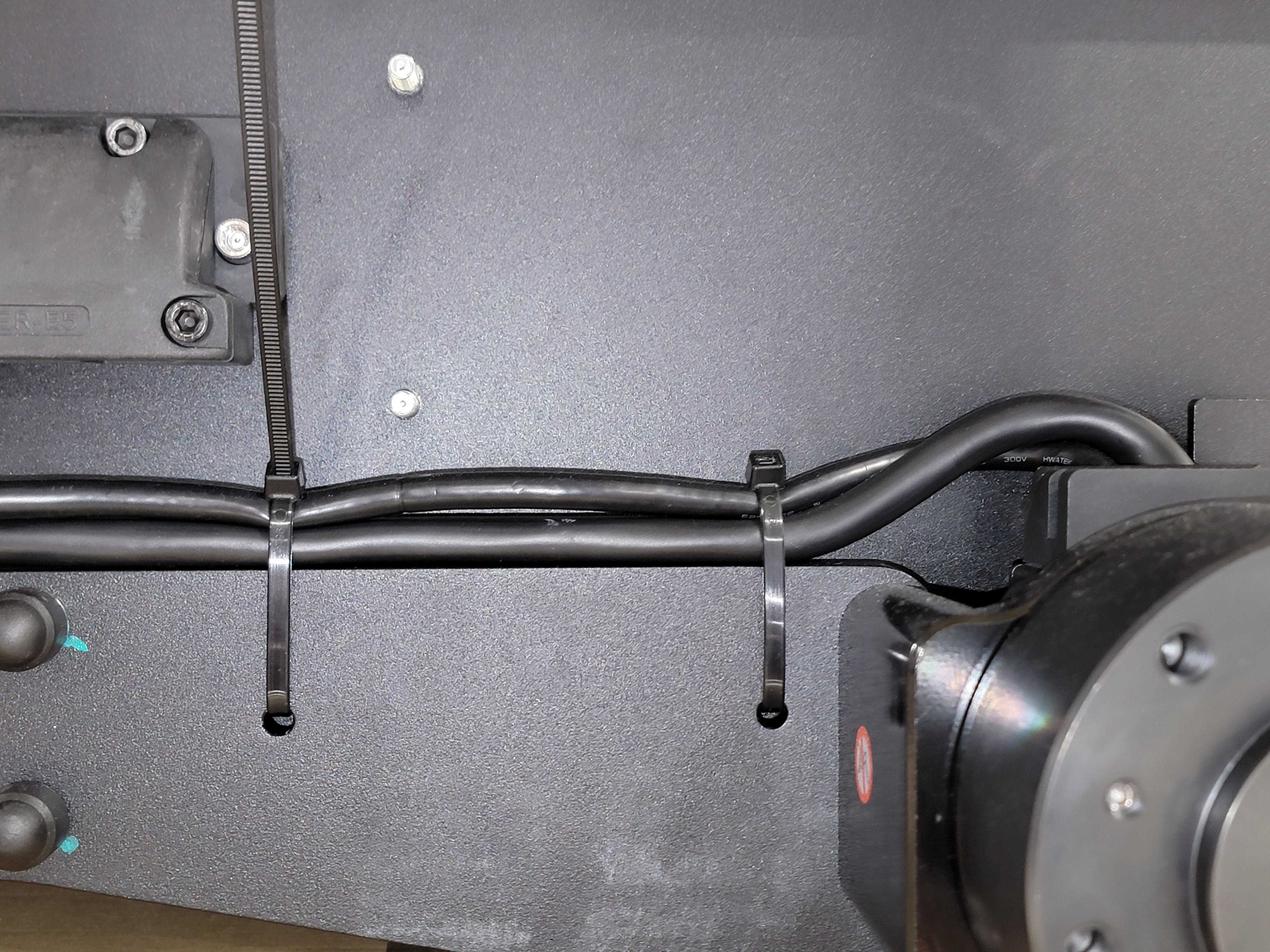
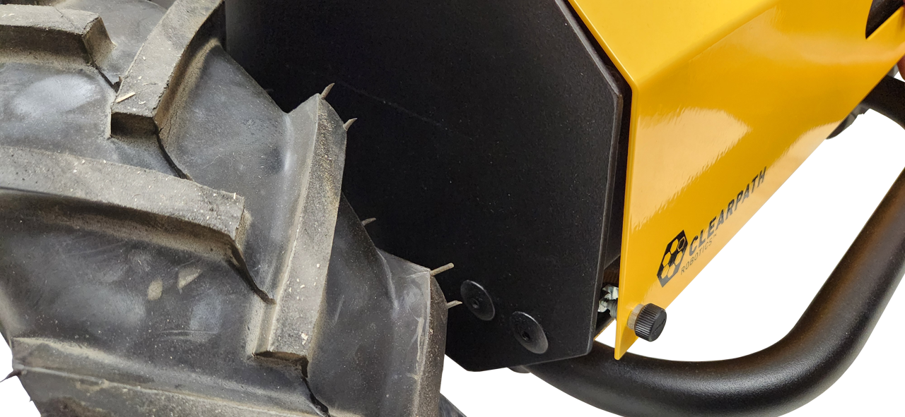
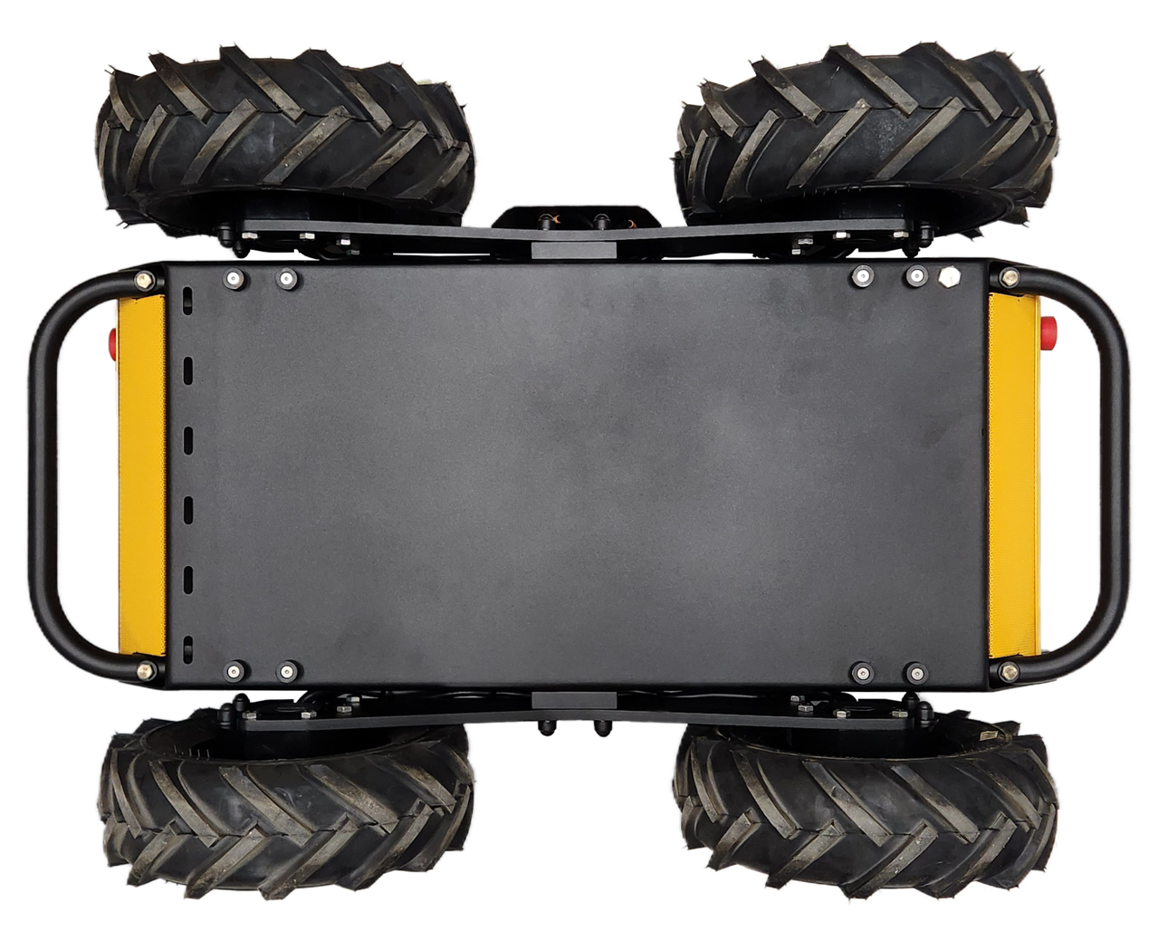
- The cable ties used to secure all four sets of motor cables are not broken (there should be two cable ties on each motor's cables).
- All four sets of the motor cables are not touching the adjacent wheel, and are secured by cable ties in a way that would prevent this from happening.
- The motor cables have not been damaged due to contact with the wheels.
Husky is an all-terrain IP54-rated robot, but it is not waterproof. Care should be taken that no part of the main chassis is ever submerged in water. When the chassis becomes wet or dirty, wipe it down with a damp cloth and dry with a towel.
If water is suspected to have entered the Husky chassis, power off the robot, open the top plate to ensure that any water has drained out through the drain plug, and allow Husky to dry fully (for a minimum of 24 hours) prior to putting it back into service.
Clean or Replace Air Filter
The air filter is used to prevent dirt and dust from entering the robot at the front air intake. It must be cleaned or replaced on a regular basis. High-dust environments will require more frequent maintenance.
The air filter is foam and can be washed, then reused.
Procedure:
- Remove the front Livery panel by loosening the quarter-turn latches
and lifting the panel up. Be careful not to damage the Emergency Stop
Button while removing the panel.
- Remove the air filter.
- Wash the filter with water and allow it to dry fully. (Alternatively, replace with a new filter.)
- Install the clean filter.
- Replace the front livery panel by aligning the pins and tighten the quarter-turn latches.
Battery Cell Balancing
Husky is powered by LiFePO4 batteries. The function and health of these batteries is monitored by a Battery Management Unit—(BMU)—which is internal to each of the battery packs.
Over the operating life of Husky, the State of Charge—(SoC)—of the batteries may start being misreported, accompanied by a higher voltage difference between the batteries' cells. Ideally; battery cells should be within a range of 50 mV. If the cell voltage difference is larger than 50 mV; Husky's batteries may suddenly drop in SoC while operating, or the Husky may unexpectedly shut off.
You should cell balance the batteries at least once per week to avoid this issue.
- Place the robot on a level surface.
- Power off the robot.
- Confirm the robot's circuit breaker is in the On position.
- Connect the manual charger.
- Let the batteries charge for at least 12 hours.
The intention of the Battery Cell Balance is to reach 100% SoC, and then charge for an additional hour while the robot is off. The suggested charge times above may be shorter if:
- Husky's batteries are already close to 100% SoC,
- Or you are using an upgraded manual charger.
Monthly Preventative Maintenance
Perform the following tasks once every month.
Tire Pressure
The Husky's tires get filled through the Schrader valve stem. This stem is close to the rim, to avoid damage from door frames and other obstacles. Some air pumps' chucks are too large to seal against this Schrader valve.
We have included a Schrader valve extension in the Husky's spare parts kit.
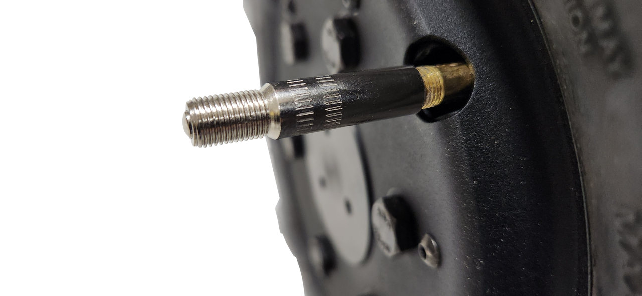
The Husky's tires should all be between 70 kPa to 140 kPa (10 psi to 20 psi).
We suggest 140 kPa for use cases on flat asphalt or concrete, to improve turning performance.
Lower tire pressures improve traction in rough and varied terrain, with rocks or other obstacles. Lower tire pressures also reduce the effective diameter of the wheel, which will increase the error of odometry readings. Odometry is calculated using the average diameter of a tire inflated to 137 kPa (20 psi).
Drivetrain Inspection
It is recommended that an auditory inspection of the robot drivetrain be performed once per month. Take note of any clicking, grinding or irregular skipping sounds while the robot is moving. Note that some clicking in the gearheads is normal during stops and starts, due to backlash between the gears.
In addition, one wheel at a time, slowly roll Husky through full wheel revolution while inspecting the tire for excessive wear, cuts, or punctures.
Annual Preventative Maintenance
Perform the following tasks once every year.
Safety Function Checks
No planned maintenance of the safety system is required. The checks below ensure that the safety systems remain operational.
Emergency Stop Buttons Check
- Confirm that the robot can be driven normally and then stop driving.
- Press the front emergency stop button, attempt to drive the robot again, and confirm that it does not move.
- Clear the front emergency stop and confirm that the robot can be driven again normally.
- Repeat the steps above for the rear emergency stop button and any wireless emergency stop buttons.
Debug Panel Door Check
- Confirm that the robot can be driven normally and then stop driving.
- Open the rear debug panel door, attempt to drive the robot again, and confirm that it does not move.
- Close the rear debug panel door, clear the emergency stop condition, and confirm that the robot can be driven again normally.
Emergency Stop Braking Check
- Remove any payload from your robot.
- Turn the robot on.
- Find a 10 metre stretch of flat ground. At the 5 metre point, mark the ground with a braking test starting point.
- Drive the robot at 1 m/s.
- Press an Emergency Stop button as the robot's front tire touches the braking test mark.
- Measure the braking distance from the mark, to the stopped position of the front tire. Confirm that the stopping distance was less than 40 cm.
Contact our Support Team if the stopping distance was more than 40 cm.
36-Month Preventative Maintenance
Perform the following tasks once every thirty-six months.
Battery Health Check
Husky's batteries are expected to last for at least 36 months of continuous operation. The actual lifetime experienced will vary greatly depending on the usage and operating environment. Contact Support for an in-depth assessment of the battery's health if you have any concerns.
Hardware Maintenance
Common Replacement Items
This does not cover the full bill-of-materials for your robot. These items are things we consider critical, so you may want to keep spares on hand. You can get any replacement part by contacting support@clearpathrobotics.com, including parts not listed here.
| Description | What Subsystem Is This Used In? | CPR Item | Manufacturer | Manufacturer Item | Maintenance Procedure |
|---|---|---|---|---|---|
| Fuse, 3A | System Interface Assembly (F2, F3, F4, F5, F8) | - | Littelfuse | 0453003.MR | Replacing board mount fuses |
| Fuse, 5A | System Interface Assembly (F6, F10) | - | Littelfuse | 0454005.MR | Replacing board mount fuses |
| Fuse, 8A | System Interface Assembly (F7, F9) | - | Littelfuse | 0453008.MR | Replacing board mount fuses |
| Fuse, 10 A | System Interface Assembly (F52, F53, F54, F55, F56, F57, F58) | - | Littelfuse | 0297010.WXT | Replacing blade mini fuses |
| Fuse, 10 A | System Interface Assembly, and System Interface Assembly's Standby Power Cable | 018897 | Littelfuse | 0297010.WXNV | Replacing blade mini fuses |
| Fuse, 20 A | System Interface Assembly | 032295 | Littelfuse | 0297020.U | Replacing blade mini fuses |
| Fuse, 40 A | Power Distribution's Large VBAT Contactors | 023567 | Littelfuse | 142.5631.5402 | Replacing BF1 fuses |
| Fuse, 50 A | Power Distribution's Manual Charger | 029139 | Littelfuse | 142.5631.5502 | Replacing BF1 fuses |
| Fuse, 60 A | Batteries, Power Distribution's Mobility Contactors, Power Distribution's Shunt Brake | 029140 | Littelfuse | 142.5631.5602 | Replacing BF1 fuses |
| Fuse, 150 A | Batteries | 029145 | Littelfuse | 142.5631.6152 | Replacing BF1 fuses |
| Air Filter | Fans | 032403 | Clearpath Robotics | - | Air Filter Maintenance |
| Tire | Mobility | 000269 | Carlisle | 5100201 | Tire Maintenance |
| Tire's Inner Tube | Mobility | 000435 | Carlisle | 323790 | Tire Maintenance |
Critical Items
These items are unlikely to fail in normal use. We are providing this data because some customers want spares on hand for anything that could impact their schedule.
| Description | What Subsystem Is This Used In? | CPR Item | Manufacturer |
|---|---|---|---|
| Battery | Batteries | 025047 | Clearpath Robotics |
| Battery Manual Charger | Spare Parts | 032729 | Clearpath Robotics |
| Main PCBA | System Interface Assembly | 030449 | Clearpath Robotics |
| BLDC Motor Controller PCBA | System Interface Assembly | 030377 | Clearpath Robotics |
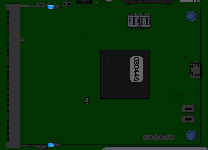
| Common Core PCBA, (MCU) | System Interface Assembly | 030446 | Clearpath Robotics |
| 12 V DC-DC PCBA | System Interface Assembly | 030430 | Clearpath Robotics |
| 24 V DC-DC PCBA | System Interface Assembly | 030433 | Clearpath Robotics |
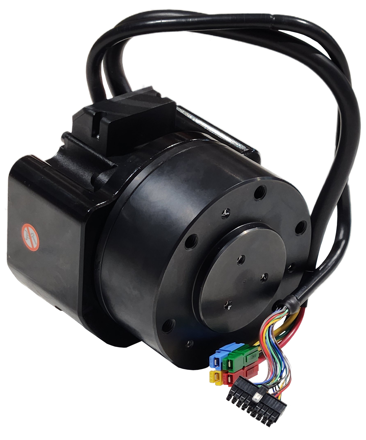
| Gearmotor | Mobility | 031514 | Clearpath Robotics |
| Fan | Fans | 031356 | Clearpath Robotics |
| Computer | Computer | 032741, or 032742 | Clearpath Robotics |
| Network Switch | Network Switch | 033443 | Clearpath Robotics |
Wiring Diagram
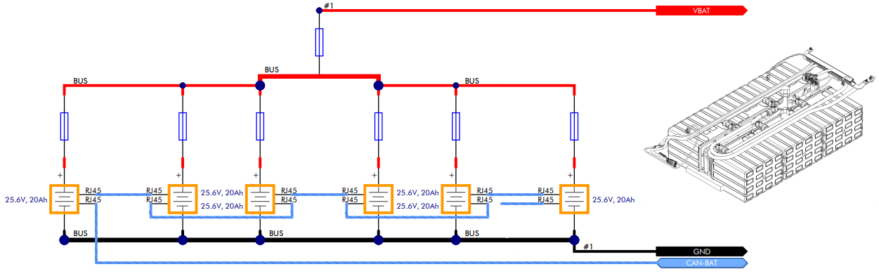
Wiring diagrams help diagnose the cause of issues, such as damaged cables or loose connections. This wiring diagram lists Clearpath's 6 digit item numbers for circuit boards and cables. The diagram does not include pinouts for individual cables.
Please contact our Support Team if you need more debugging information, or want a replacement cable.
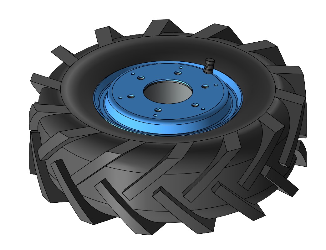
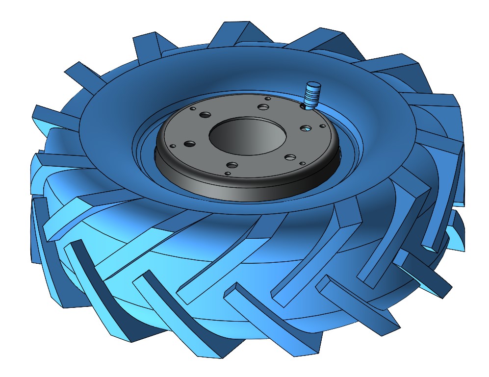
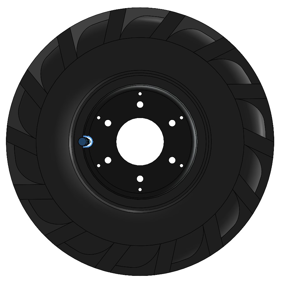
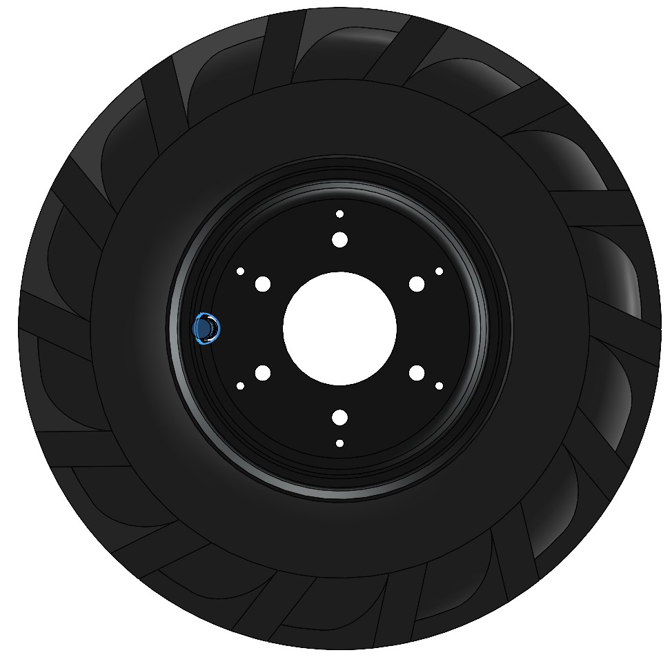
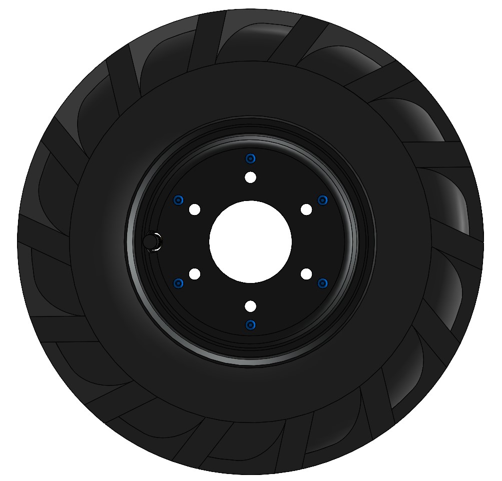
Tire and Inner Tube
CAUTION
Place the robot up on blocks prior to replacing the tire or inner tube. The robot may tip over if you remove a wheel without stabilizing the chassis.
To replace the tire and inner tube:
-
Shut off the robot's circuit breaker.
-
Remove the six M8×1.25 screws holding the wheel to the motor.
-
Deflate the tire by pressing on the Schrader valve's core.
-
Remove the six M4×0.7 screws and nuts that hold the split rim together.

-
Remove the outer rim.
-
Remove the tire and tube from the inner rim.
-
Replace the tire and/or tube as needed with new parts. Make sure the tire's chevron treads are facing the correct direction, as the left and right wheels have different tread orientations. Ensure that the tube is installed in the tire and inflated only far enough that it takes its shape. Inflating further will make reassembly difficult.
-
Place the tire—(with inner tube)—onto the inner rim, aligning the valve stem with the notch in the rim.
-
Place the outer rim on top, aligning the value stem with the notch in the rim.
-
Reinstall the six M4×0.7 screws and nuts, tightening them in a star pattern to 2 N·m.
noteIt may be necessary to use three longer M4×0.7 screws on a temporary basis to help pull the inner and outer rims together and ensure alignment, allowing the first three standard M4 screws to be installed. Then, the temporary M4×0.7 screws can be removed and the standard ones installed. As you tighten the screws, ensure that the valve stem is not being pinched.
-
Inflate the tire to 140 kPa (20 psi).
-
Place the wheel on the motor and reinstall the six M8×1.25 screws, tightening them in a star pattern to 20 N·m.
Motors
To remove the motors:
- Shut off the robot's circuit breaker.
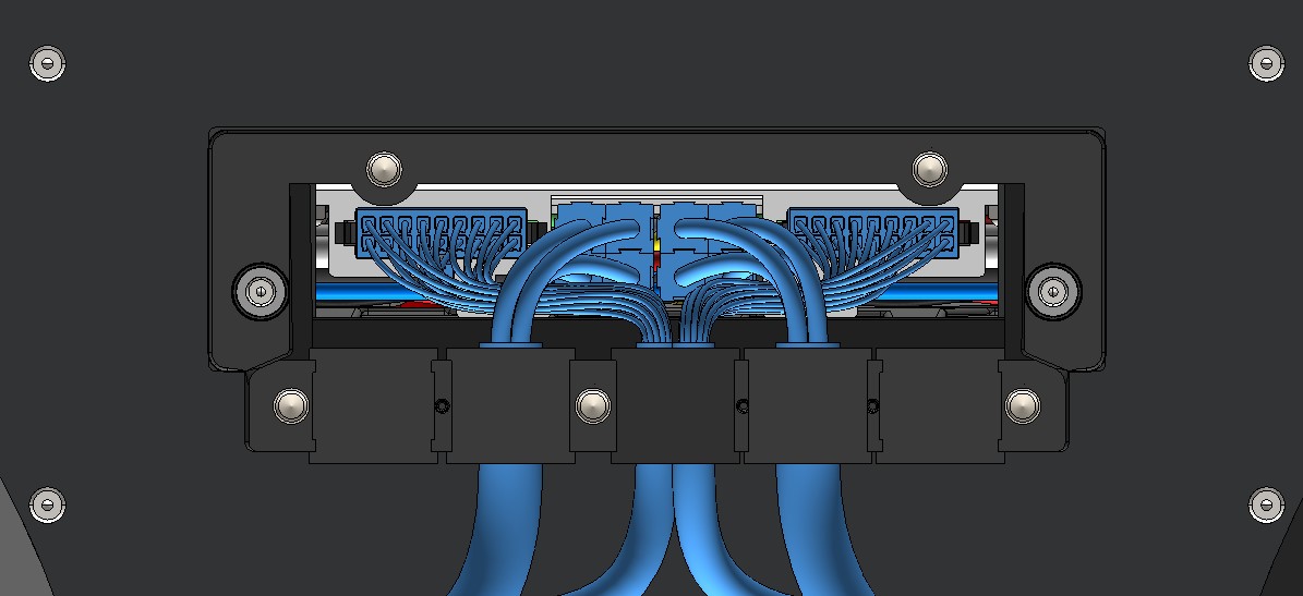
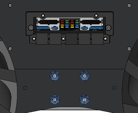
- Remove the cable gland cover on the side of the robot. This cover is held with 5 socket head screws.
- Disconnect both sets of motor power and cables from the chassis on the side of the robot with the motor being replaced. The thick power cables are removed by pulling on the cable. The thinner data cables have a latch on the connector; press on the latch and then pull on the connector.
- Remove the suspension beam from the chassis by removing the four nuts and washers.
- Remove the wheel from the motor (see above).
- Remove the motor from the suspension beam by removing the four M8×1.25 screws.
When reinstalling the motor and suspension:
- Torque the motor's 4 screws to 20 N·m.
- Gently pull both motor cables away from the motor so that the cables are held tightly along the suspension beam.
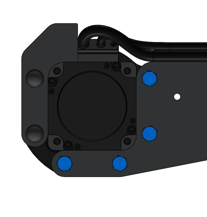
- Ensure that both cables are routed along the top face of the suspension beam, and are laid out so that the thinner cable sits on top of the thicker cable.
- Insert an 11" black cable tie into the first hole in the suspension beam (the hole closest to the motor) and tie it around the cables as they are being held.
- Ensure that the cable tie is tightened as much as possible by hand, that both cables remain above the suspension beam, and the thinner cable remains on top of the thicker cable.
- Insert another 11" black cable tie into the second hole in the suspension beam (the hole closest to the center) and tie it around the cables.
- Ensure that the cable tie is tightened as much as possible by hand, that both cables remain above the suspension beam, and the thinner cable remains on top of the thicker cable.
- Cut off the extra length of both cable ties.
- Repeat above steps for each of the remaining three motors.
- Torque the wheel's 6 screws to 20 N·m.
- Torque the suspension beam's nuts to 30 N·m. Torque these slowly, in a star pattern. Exceeding 30 N·m will damage the Husky's aluminum chassis.
- Each motor has 2 cables. Make sure both related cables go to the related connectors on the robot's chassis.
- Torque the cable gland cover's screws to 1 N·m.
Front Cover
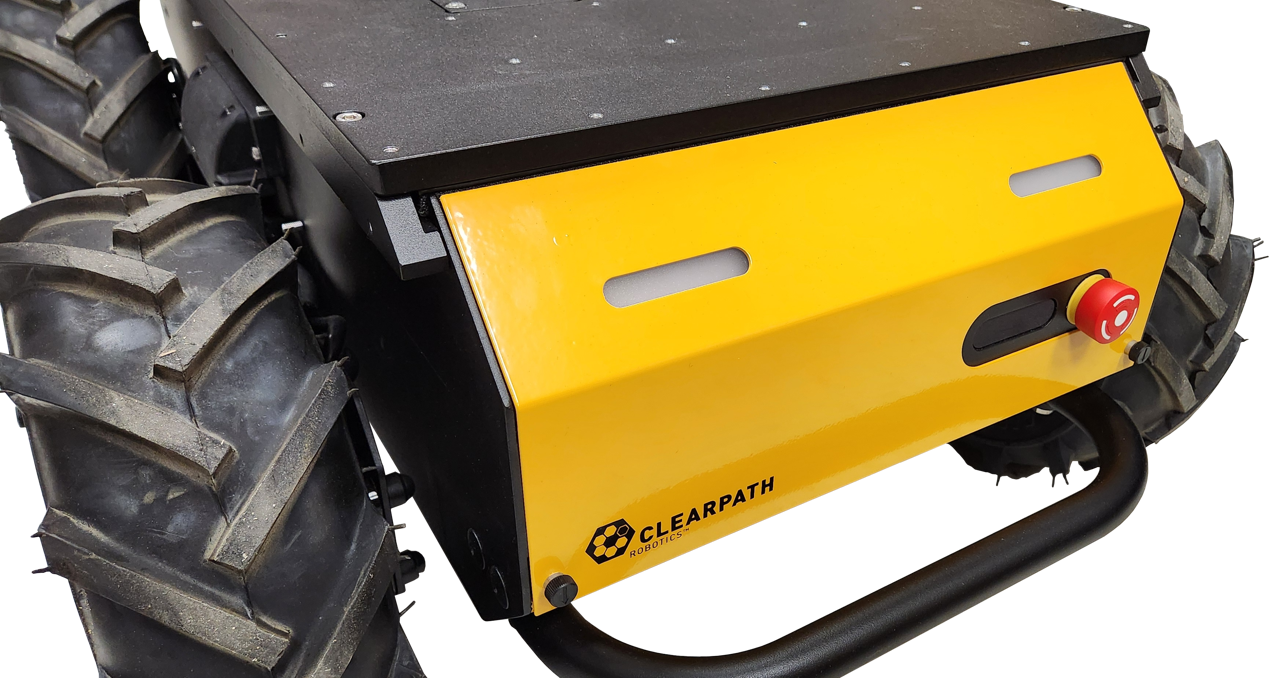
The Husky's identification labels, status lights, air filter, and some fasteners are located under the Front Cover.
To remove this cover:
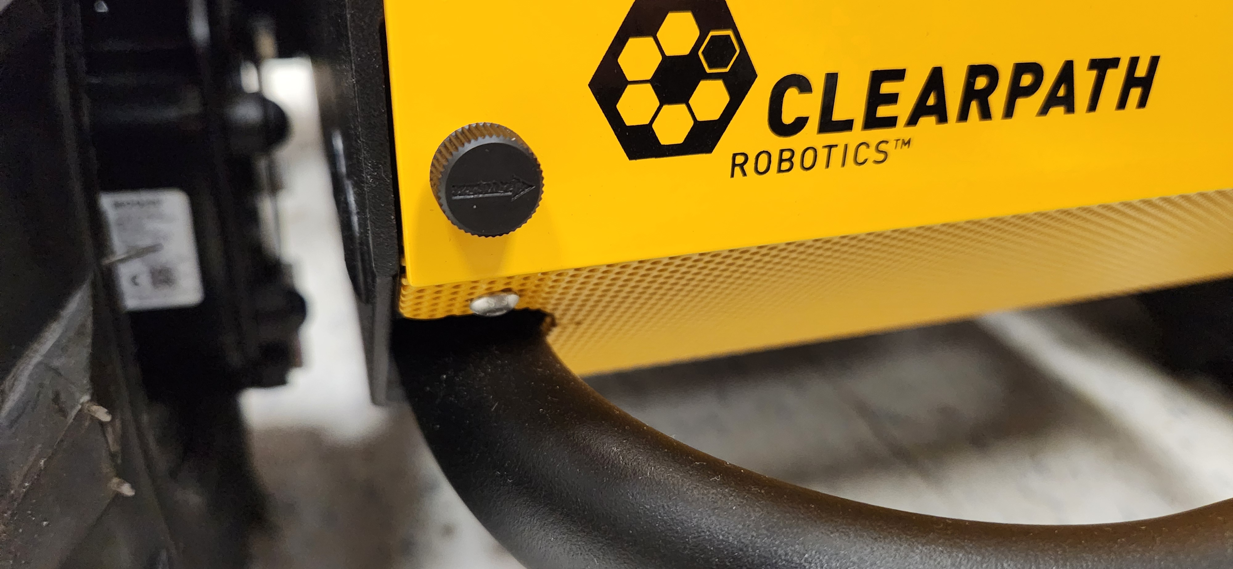
Twist the 2 thumb-latches 90°, so the arrows are horizontal.
Tilt the cover.
Lift the cover's pins from the chassis's 2 rubber grommets.
The cover must be installed during operations to maintain Husky's IP54 ingress protection rating, and reduce the risk of entrapment.
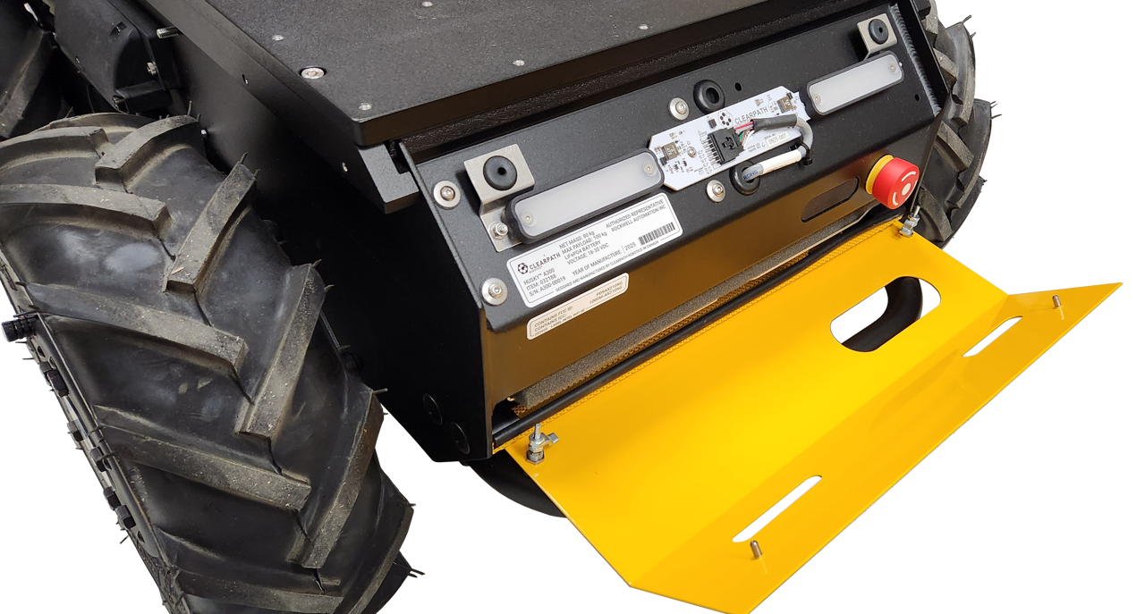
Nameplate And Regulatory
Husky's Nameplate is located under the Front Cover. The Nameplate includes regulatory marks, the product's name, serial number, and date of manufacture.
There will be other labels on the chassis with FCC information, such as the Intel Wi-Fi card shown in the attached image.
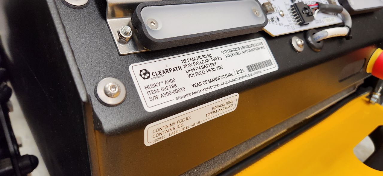
Our Removing The Front Cover section explains how to access the Nameplate.
Removing The Top Plate
To remove Husky's Top Plate:
- Turn off the Husky.
- Open the Rear Charge Port Door.
- Flip the Circuit Breaker to the Off position.
- Close the Rear Charge Port Door.
- Remove the seven M6×1 socket head screws from the Top Plate. Note that one of the screws also has a sealing washer attached to it.
- If applicable, remove any of your custom cables from the Top Plate's connector openings.
- Lift the Top Plate off of the robot.
When reinstalling the Top Plate:
- Torque the tray's 4 screws to 3 N·m.
Do not drag the Top Plate on the robot, because it may damage the bulb seal around the Husky's chassis.
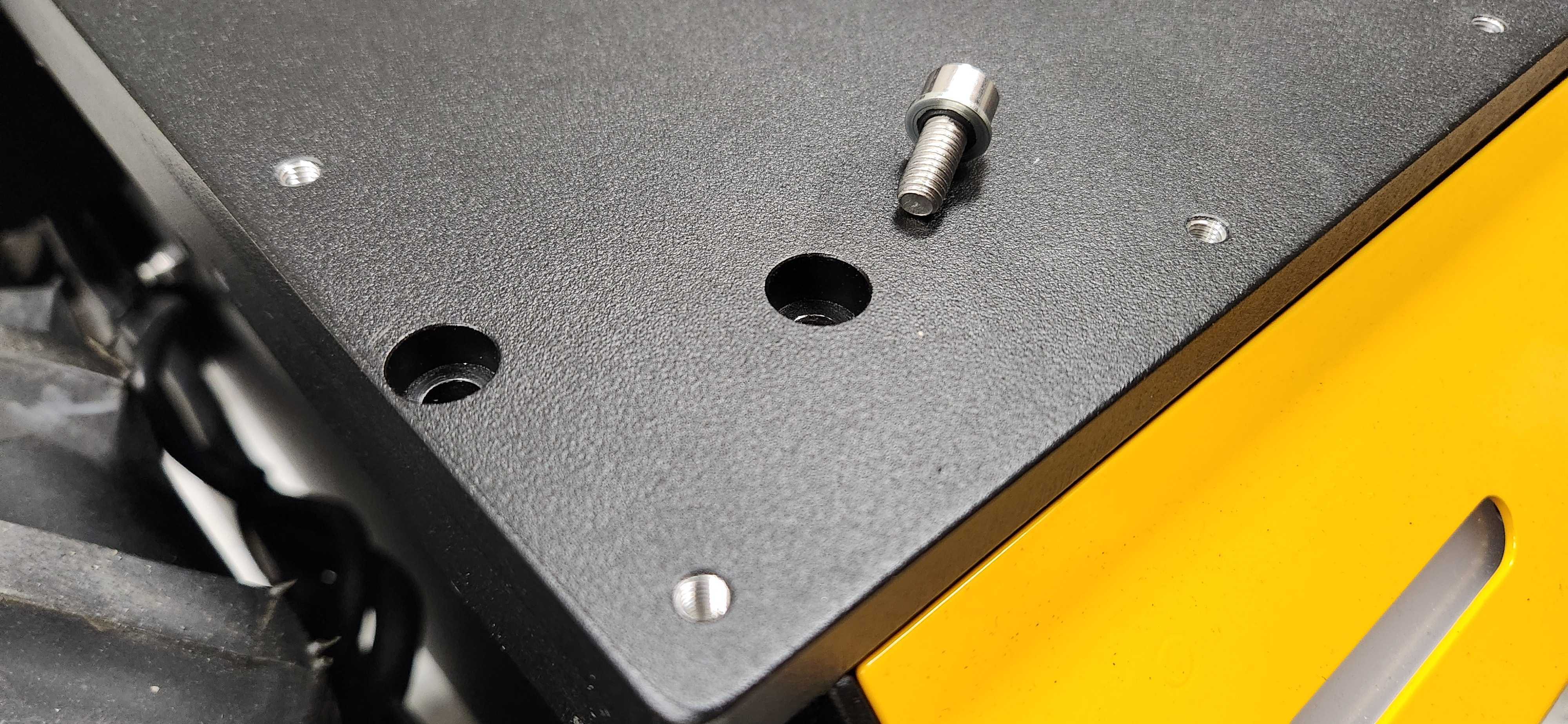
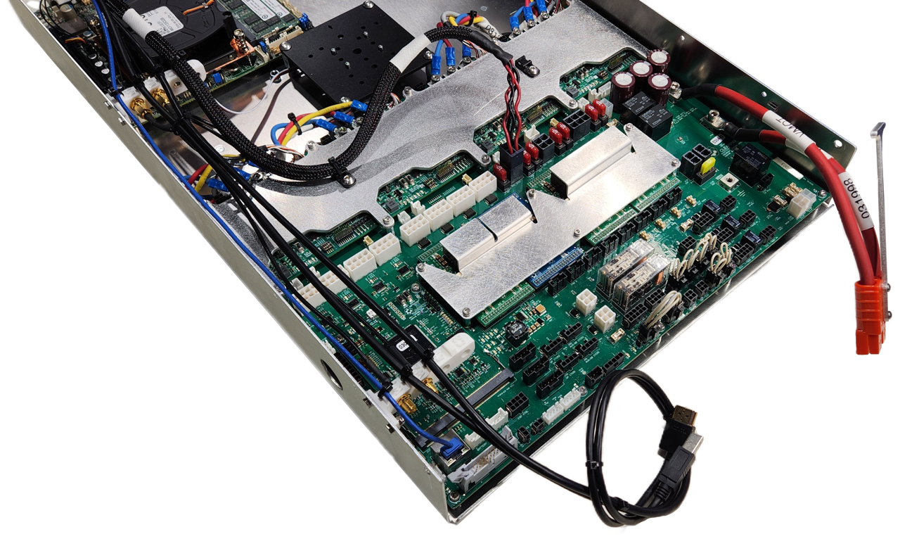
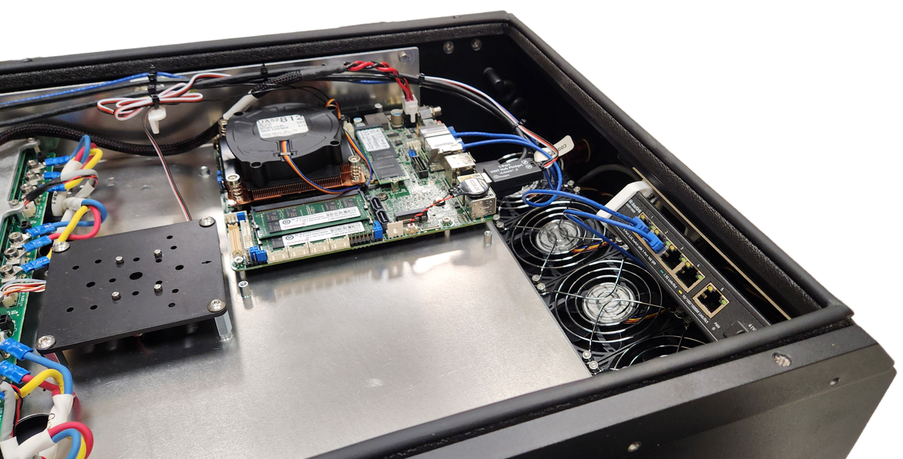
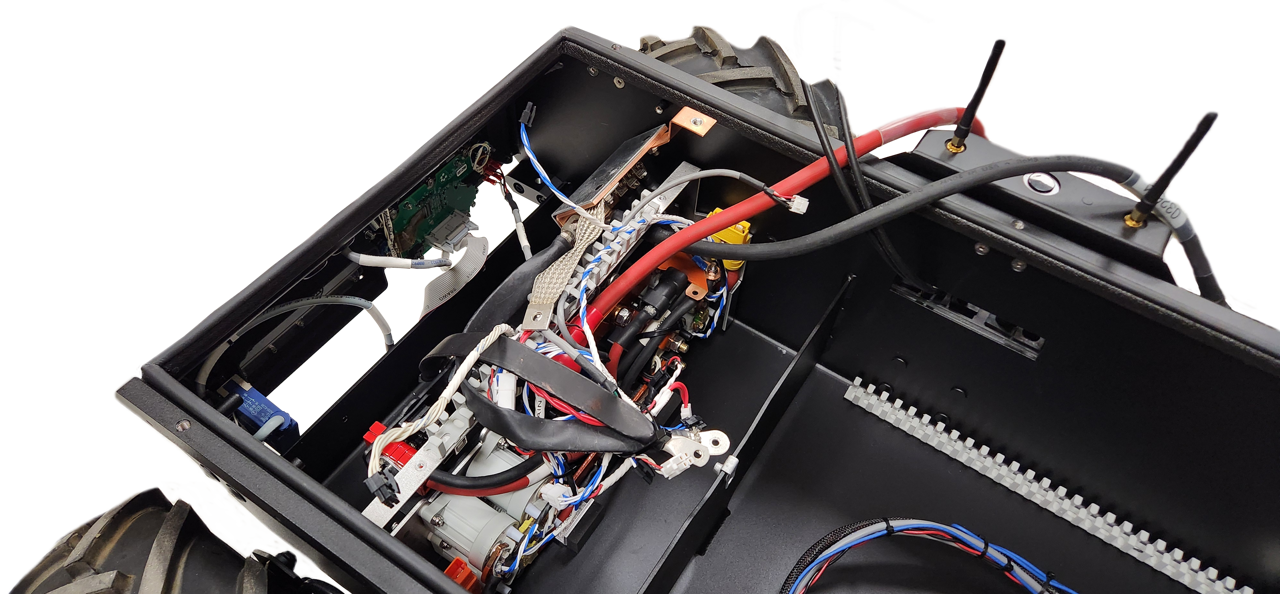
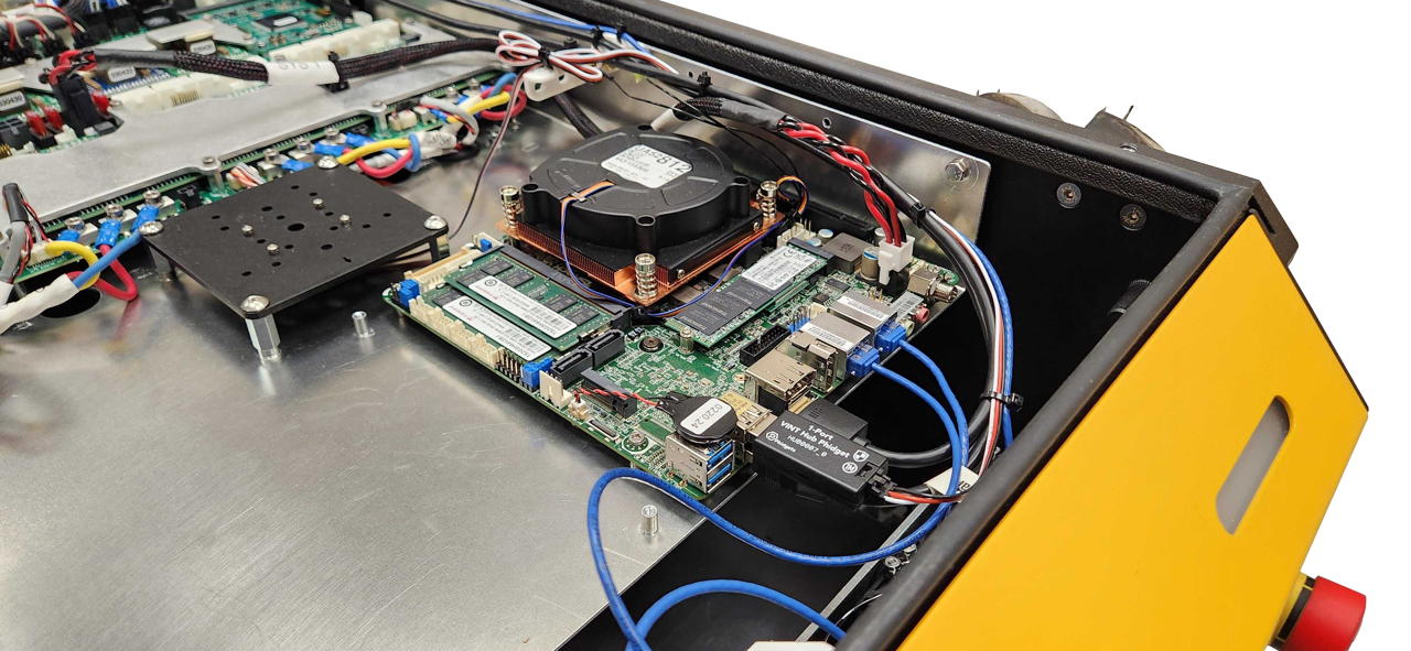
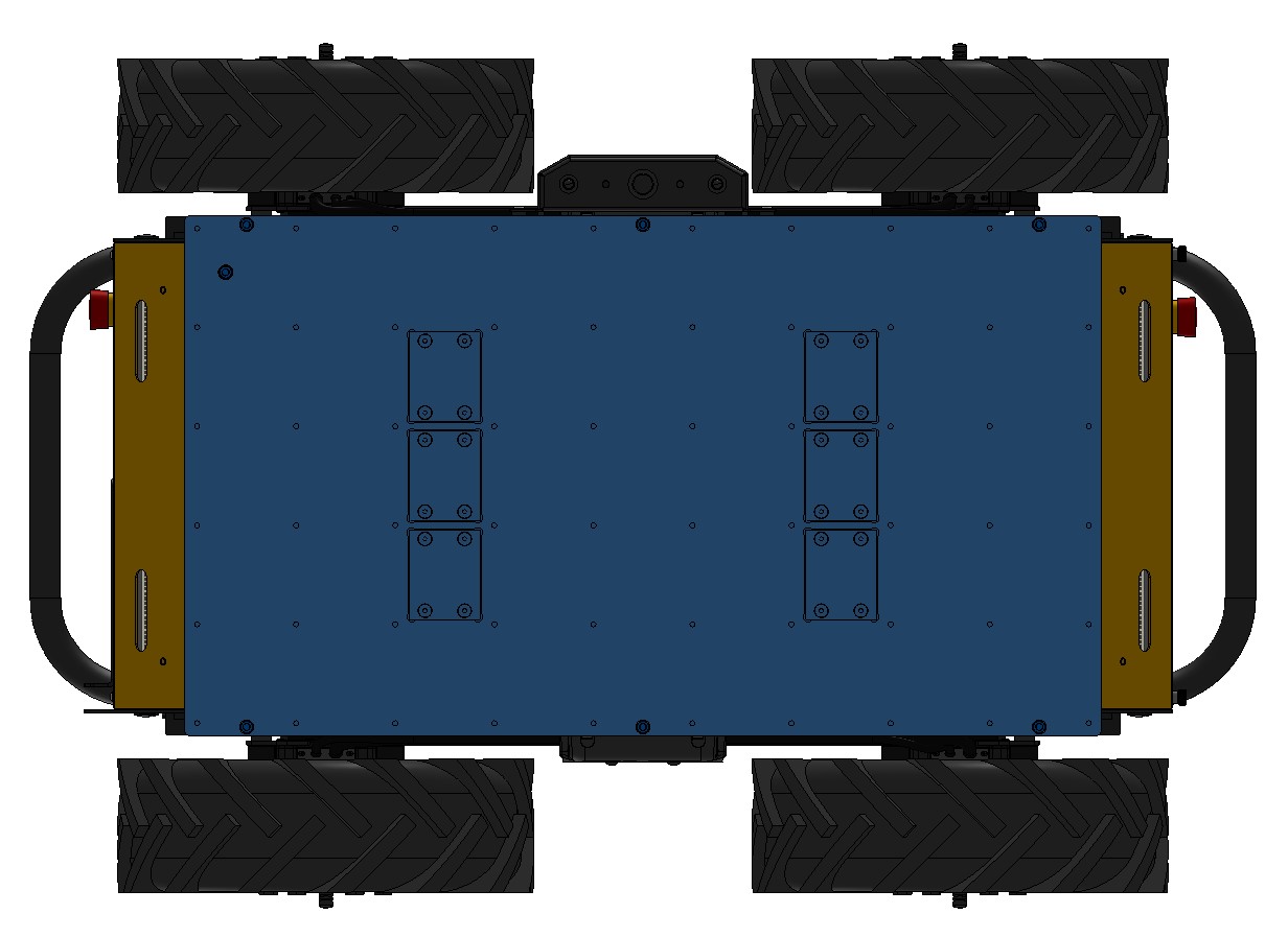
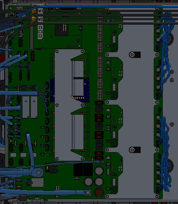
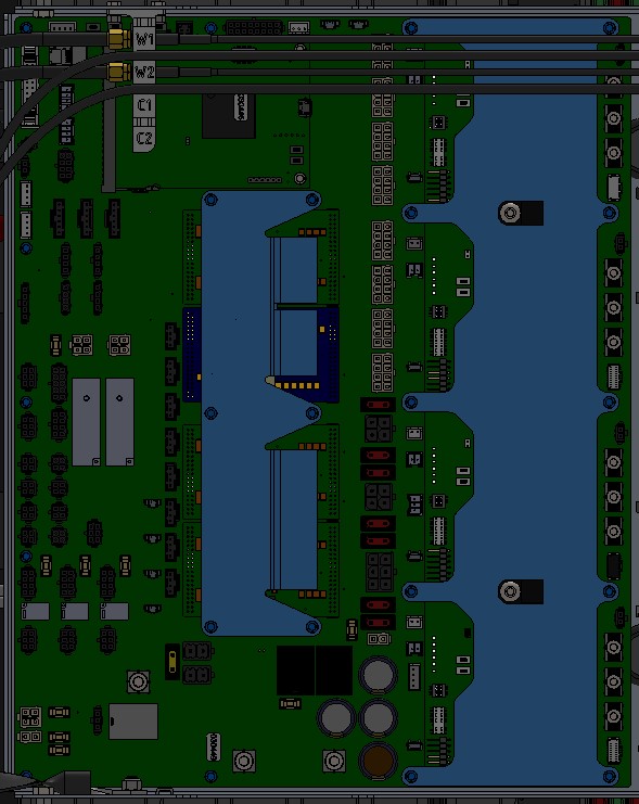
Electronics Tray
Once you have opened Husky's top, the first thing you see is the Electronics Tray. This tray includes the:
- Husky's System Interface Assembly circuit board
- Primary computer
- IMU
- Optional secondary computer or graphics card, (not shown in the image)
- Optional USB hub, (not shown in the image)
You may want to remove the Electronics Tray to access the integration bay under the tray, or to maintain Husky's Batteries and Power Distribution components.
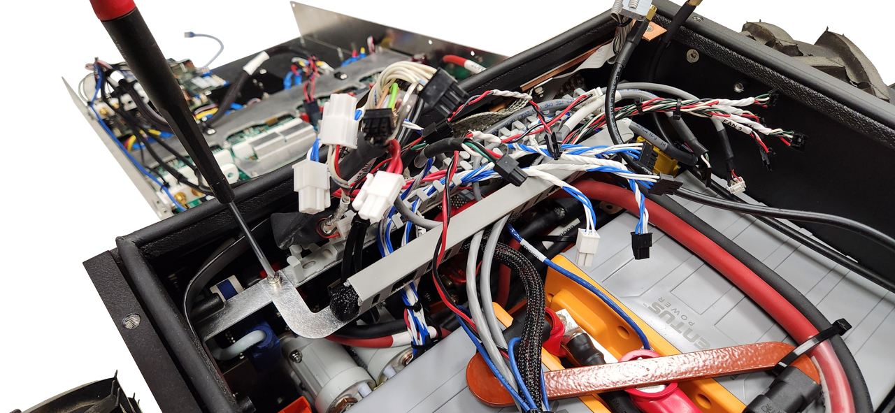
Hinging The Electronics Tray
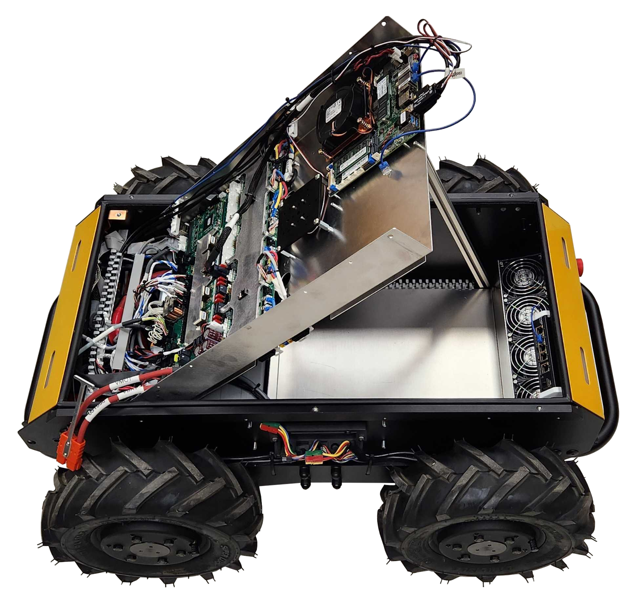
To hinge the tray:
- Shut off the Circuit Breaker
- Remove the Top Plate or Enclosure from the Husky
- Disconnect the motor cables, (2 per motor, so 8 cables total)
- Disconnect the computer's Ethernet cable from the network switch
- Disconnect the large orange connector near the rear-right of the robot. This connector provides main power, and mobility power to the Electronics Tray.
- Remove the tray's 2 front screws
- Loosen the tray's 2 rear screws, (these will become the tray's hinge pin)
- Lift the front of the tray
When reinstalling the tray:
- Torque the tray's 4 screws to 3 N·m.
Lifting the tray will expose Husky's batteries. The batteries's exposed +V terminals are always live, even when Husky's circuit breaker is in the Off position. The batteries are fused, but can still produce an electric arc if shorted to ground.
Wear protective equipment to guard your skin and eyes.
Keep the workspace clean, without any combustible materials nearby.
Review your workplace's safety procedures related to fires of LiFePO4 batteries.
Removing The Electronics Tray
To remove the tray:
-
Return the tray to the level position, (not hinged)
-
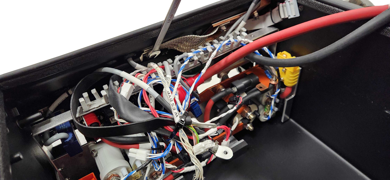
Take pictures of all the cables and connections to the System Interface Assembly. The cables have labels with names that match the PCBA's silkscreen, but pictures will help you reinstall these cables later.
-
Disconnect all the cables, (listed from the left side of the robot, towards the right):
- (Any cables from your custom integration)
- Front Ethernet cable to the network switch, (which should have been removed in the previous step)
- 2X Wi-Fi, (plastic bracket's W1 and W2)
- Current Sensor, (BATTERY I)
- HMI Display, (USER INTERFACE)
- Battery CANbus, (CAN_BAT)
- 2X Status Lights, (STATUS 1, STATUS 2)
- 2X Large VBAT Contactors, (UP CTCR1, UP CTCR2)
- 2X Shunt Brake Contactors, (AUX/SB CTCR1, AUX/SB CTCR2)
- 2X Mobility Contactors, (M CTCR1, M CTCR2)
- 4X Fans, (FAN 1, FAN 2, FAN 3, FAN 4)
- Optional, Wireless Emergency Stop Cable, (W ES)
- Wireless Emergency Stop Disable Keyswitch, (W ES BYP)
- 2X Emergency Stop Buttons, (ES1, ES2)
- Limit Switch, (CHRG INTL)
- Network Switch Power, (SYS4)
- Main Ground, (GND)
- Low Battery Shutdown, (CB KILL)
- Main Contactor, (MAIN CTCR)
- System Standby Power, (VSTBY)
- Tray Bond, (Tray's threaded stud, without identification)
- Leave the USB cable connected
- Leave the HDMI cable connected
- Large orange connector (V MOT and V SYS, which should have been removed in the previous step)
-
Remove the tray's 2 rear screws
-
Lift the tray out of the Husky. Note that the tray is still tethered to the Husky with a USB cable and a HDMI cable. Rotate the tray, and set it behind the Husky.
-
Disconnect the USB and HDMI cables from the Husky's Debug HMI area.
When reinstalling the tray:
- Torque the tray's 4 screws to 3 N·m.
- Torque the Main Ground cable's screw to 2.2 N·m.
- Torque the Tray Bond cable's nut to 3 N·m.
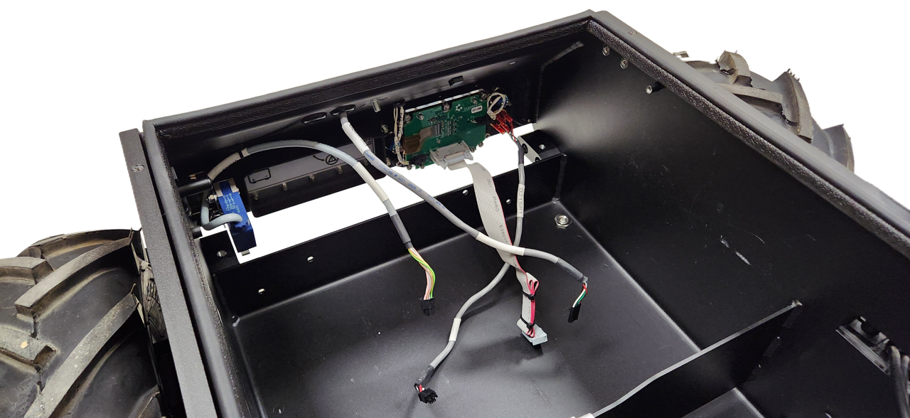
Battery Integration Tray
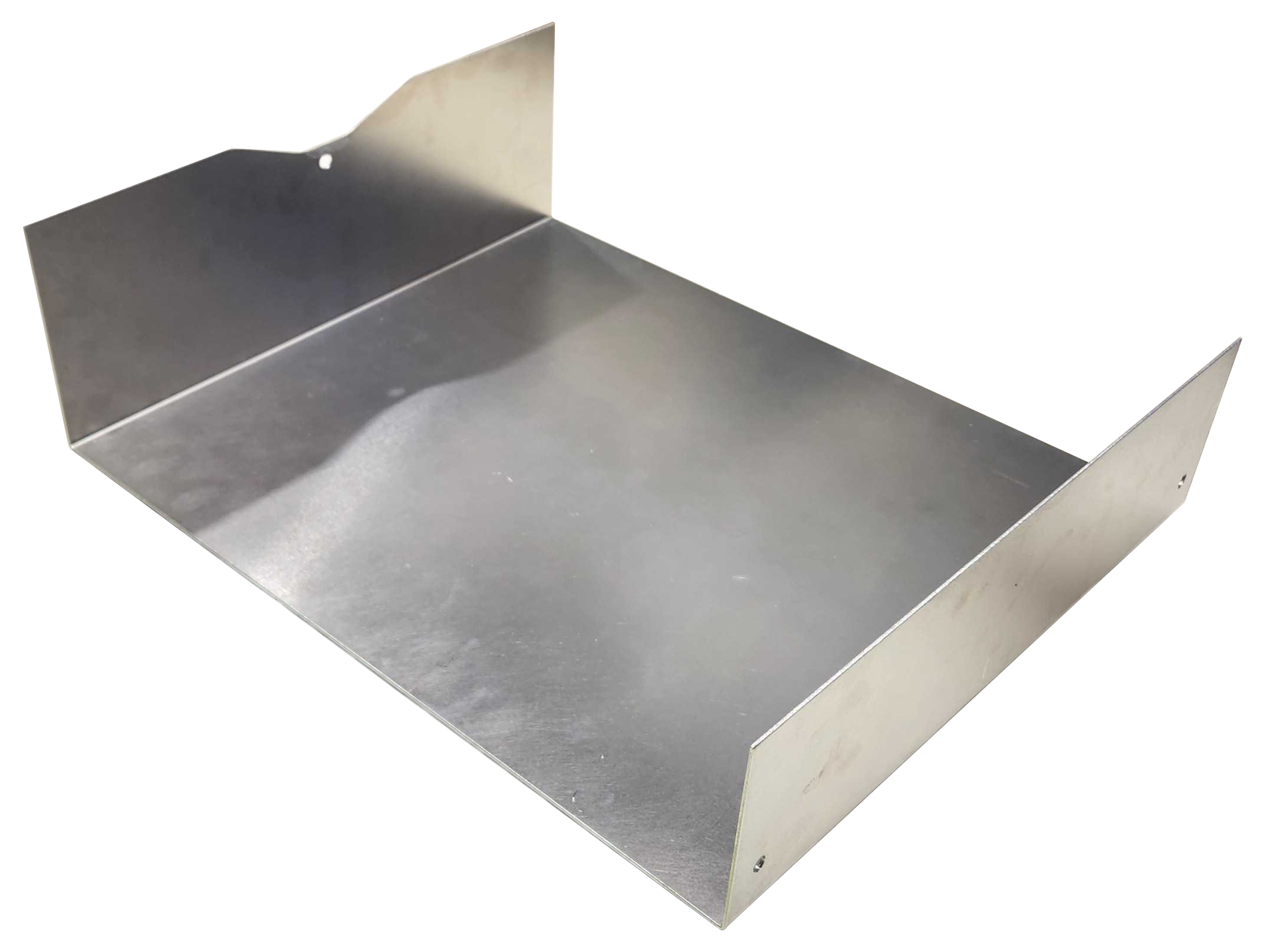
The Husky configurations with 40 Ah and 80 Ah batteries include a metal tray inside the chassis. You can mount your custom integration components on this tray.
The 120 Ah Husky fills the entire chassis volume with batteries.
To remove the tray:
- Remove the Electronics Tray, as it is blocking access to the battery volume.
- Remove the Battery Integration Tray's screws
- 3X screws for the 40 Ah Husky
- 2X screws for the 80 Ah Husky
- Remove the tray
When reinstalling the tray:
- Torque the tray's screws to 3 N·m.
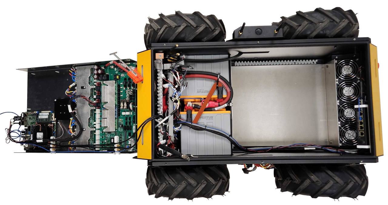
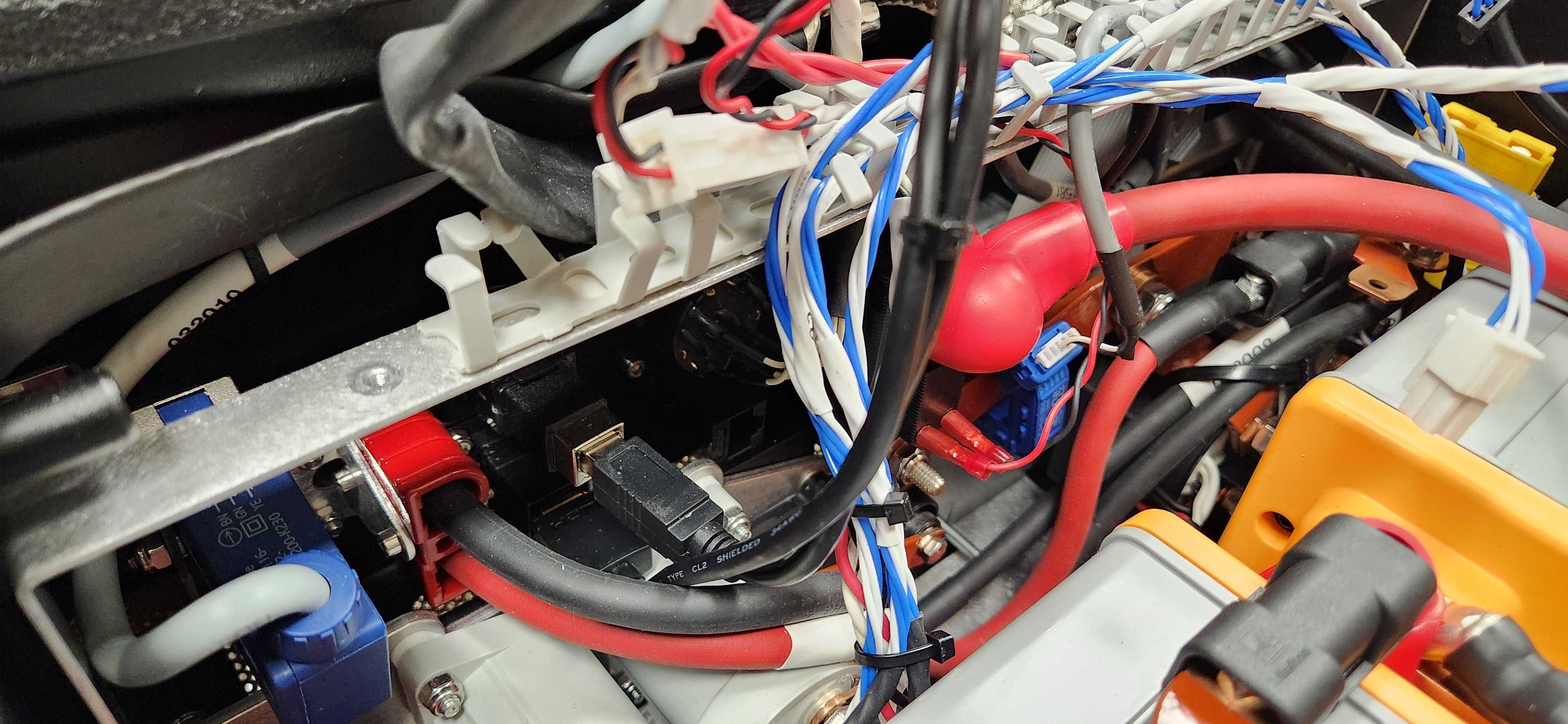
Batteries
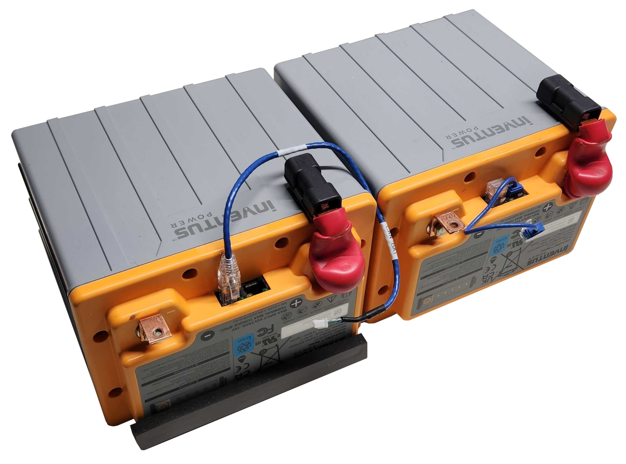
The Husky's batteries are visible once you remove the Electronics Tray. The batteries +V terminals are always live, even when the circuit breaker is in the Off position. You may want to remove the batteries to replace them, or to access the Power Distribution subassembly.
The images show the Husky 40 Ah configuration which has 2 batteries. The 80 Ah and 120 Ah configurations follow a similar process, but with 4 or 6 batteries.
Husky's batteries should last 3000 charge cycles if they are charge balanced at least once per week, and not left in a depleted state.
If you order new batteries from Clearpath Robotics, ask us to configure the batteries for a Husky A300. We will configure the battery software addresses and CAN address before shipping them to you.
To remove the batteries:
-
Remove the Electronics Tray.
-
Loosen the cable comb bracket's 2 screws, and then fold it towards the front of the robot. This will give you better access to the batteries.
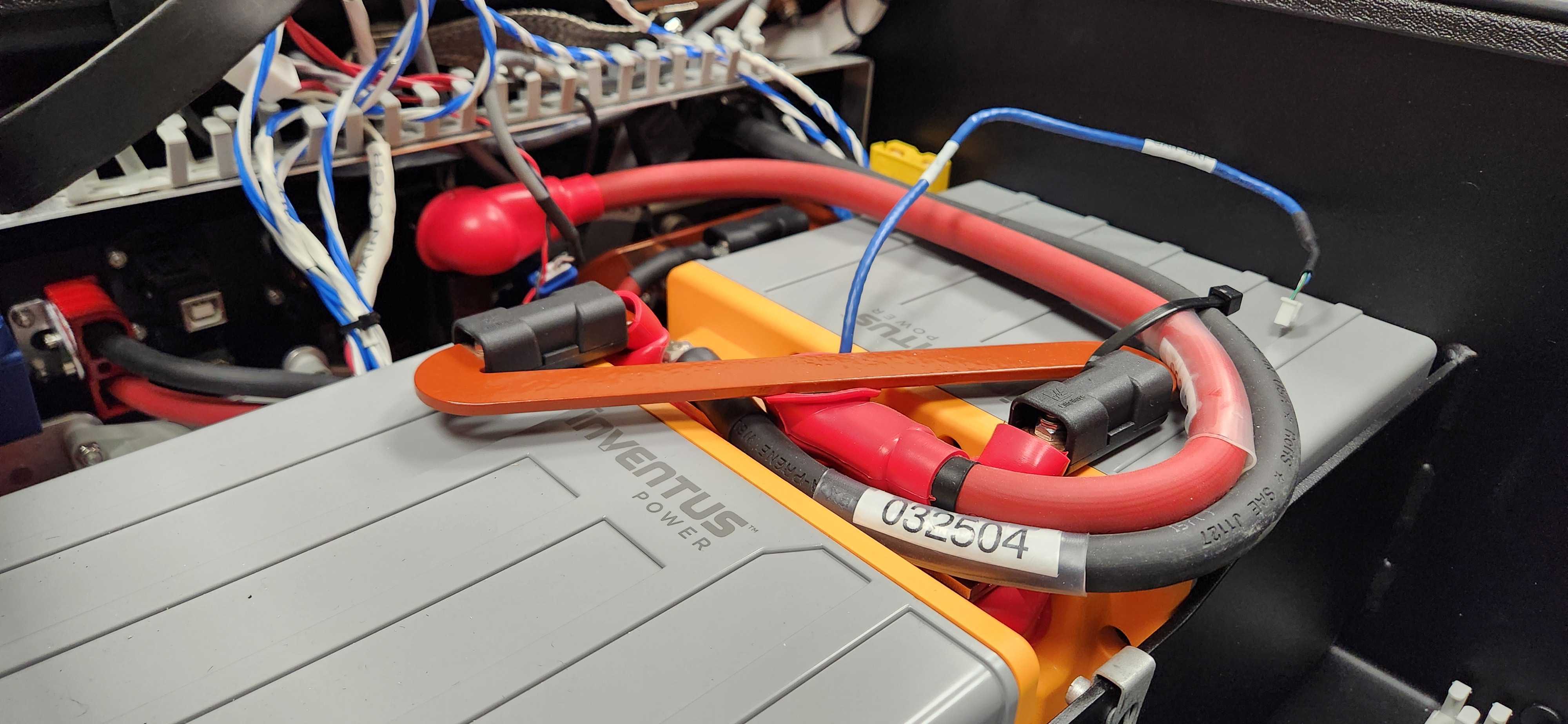
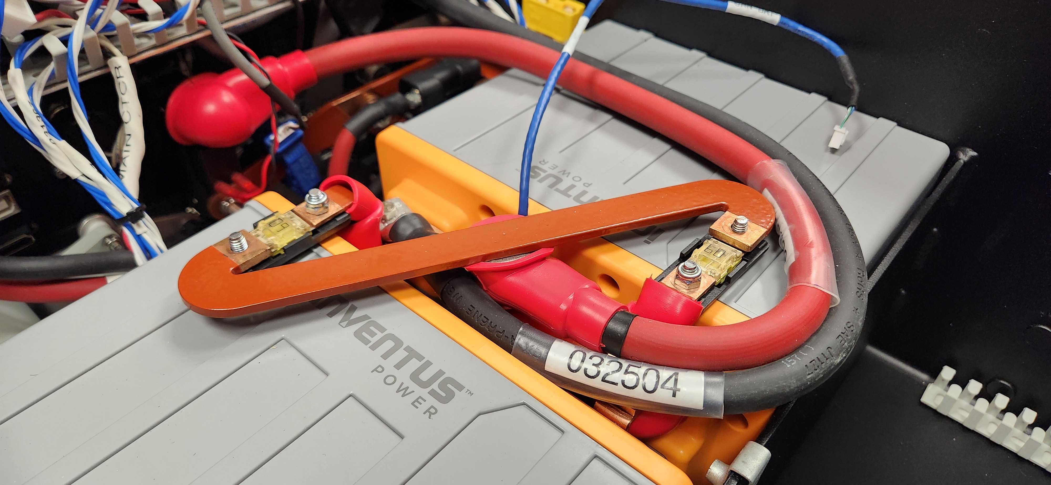
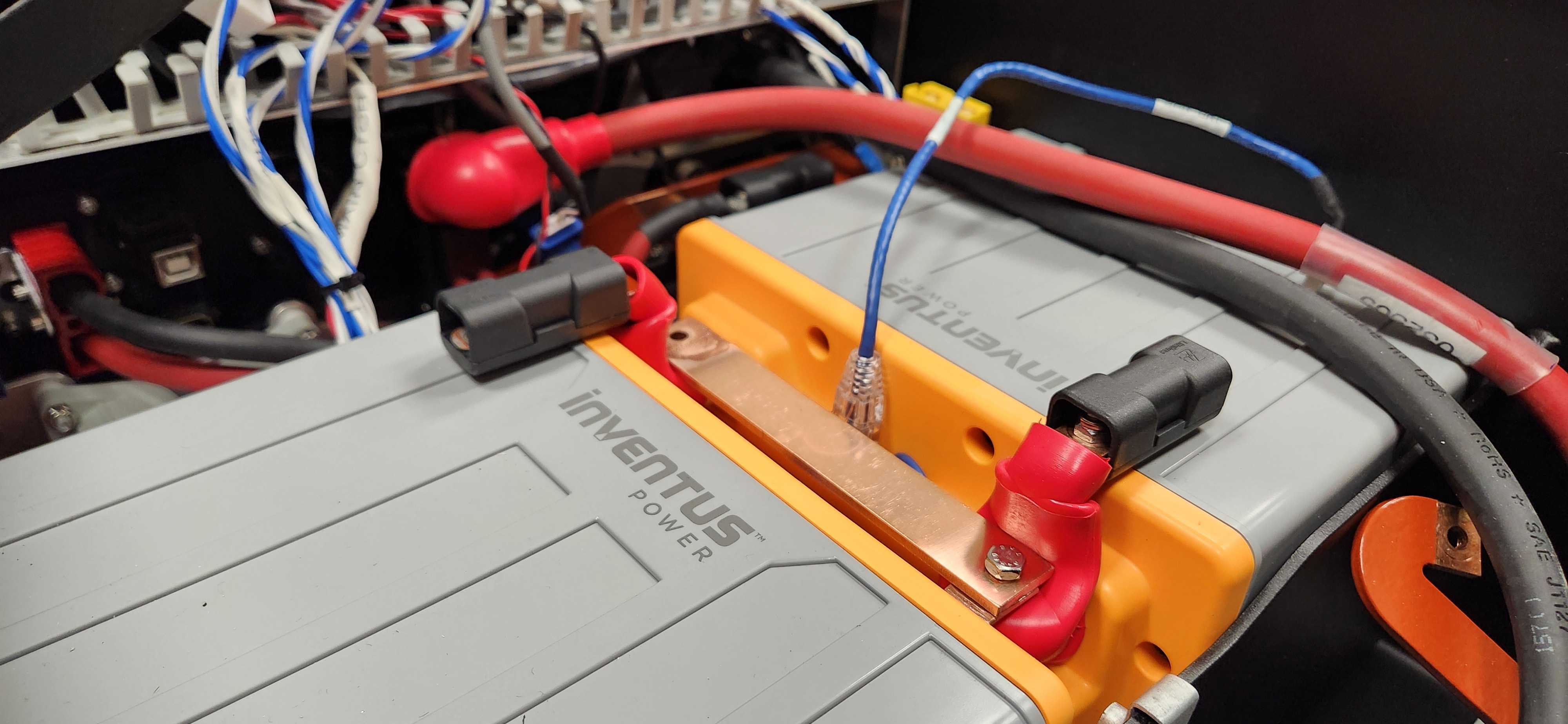
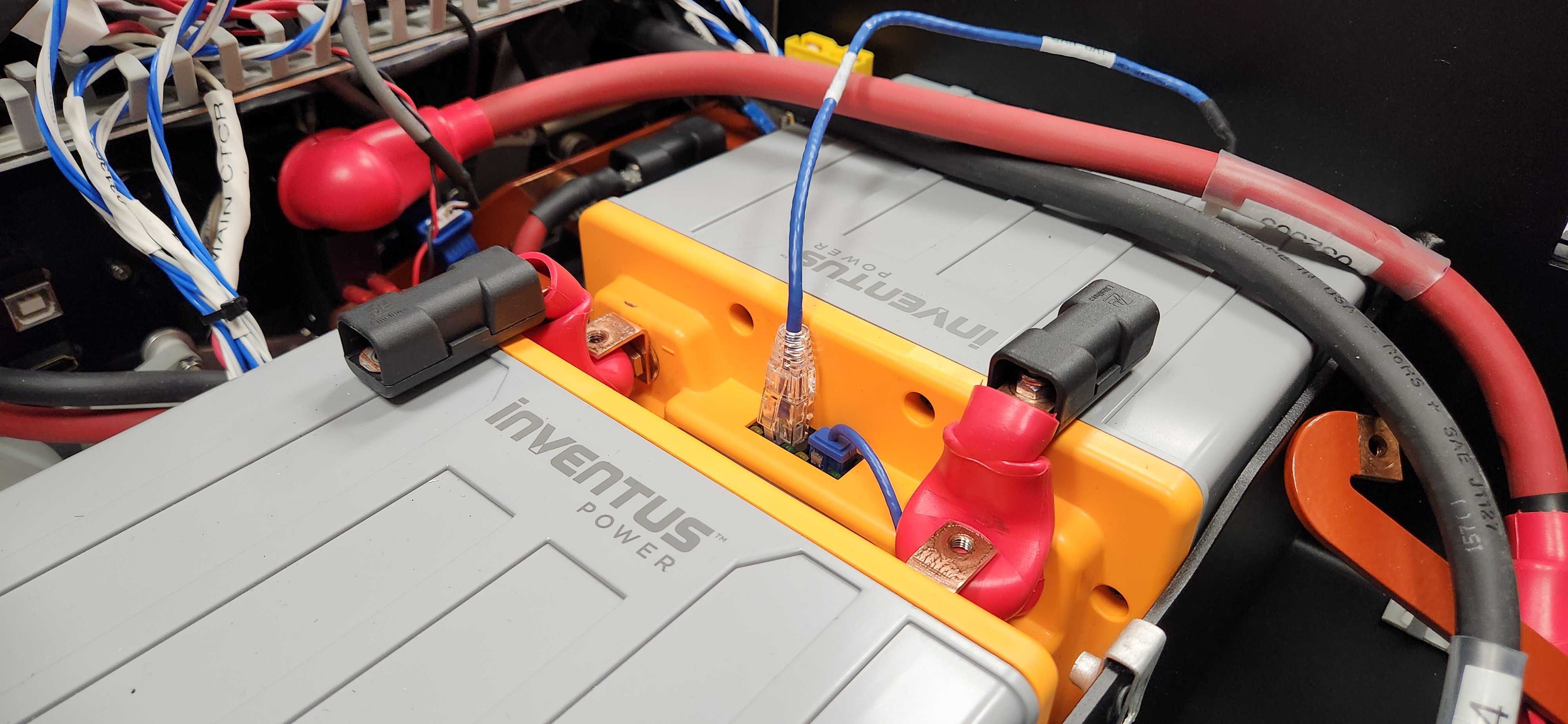
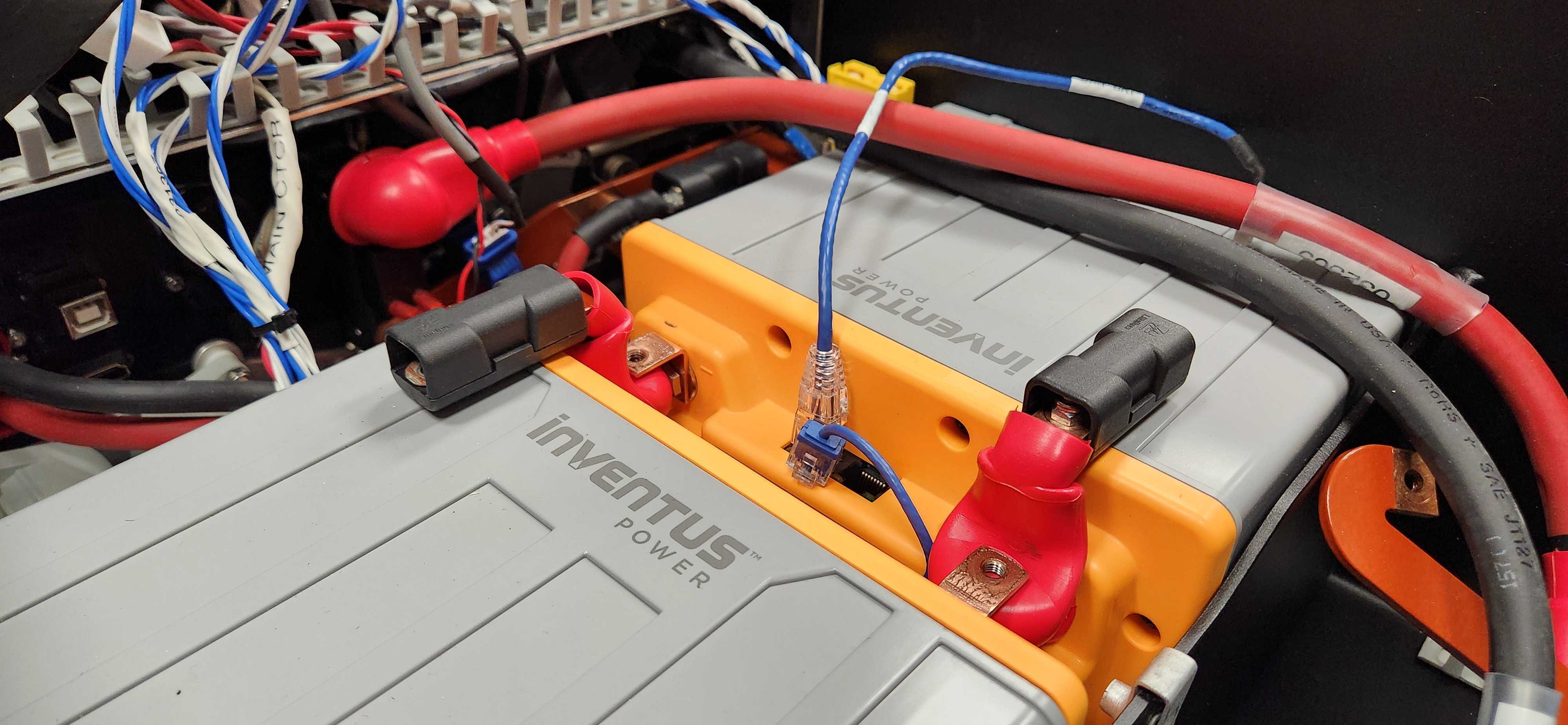
Batteries Are Visible After the Electronics Tray And Cable Comb Have Been Removed -
Remove the plastic covers from the fuse holders. These are always live voltage, up to +30 VDC.
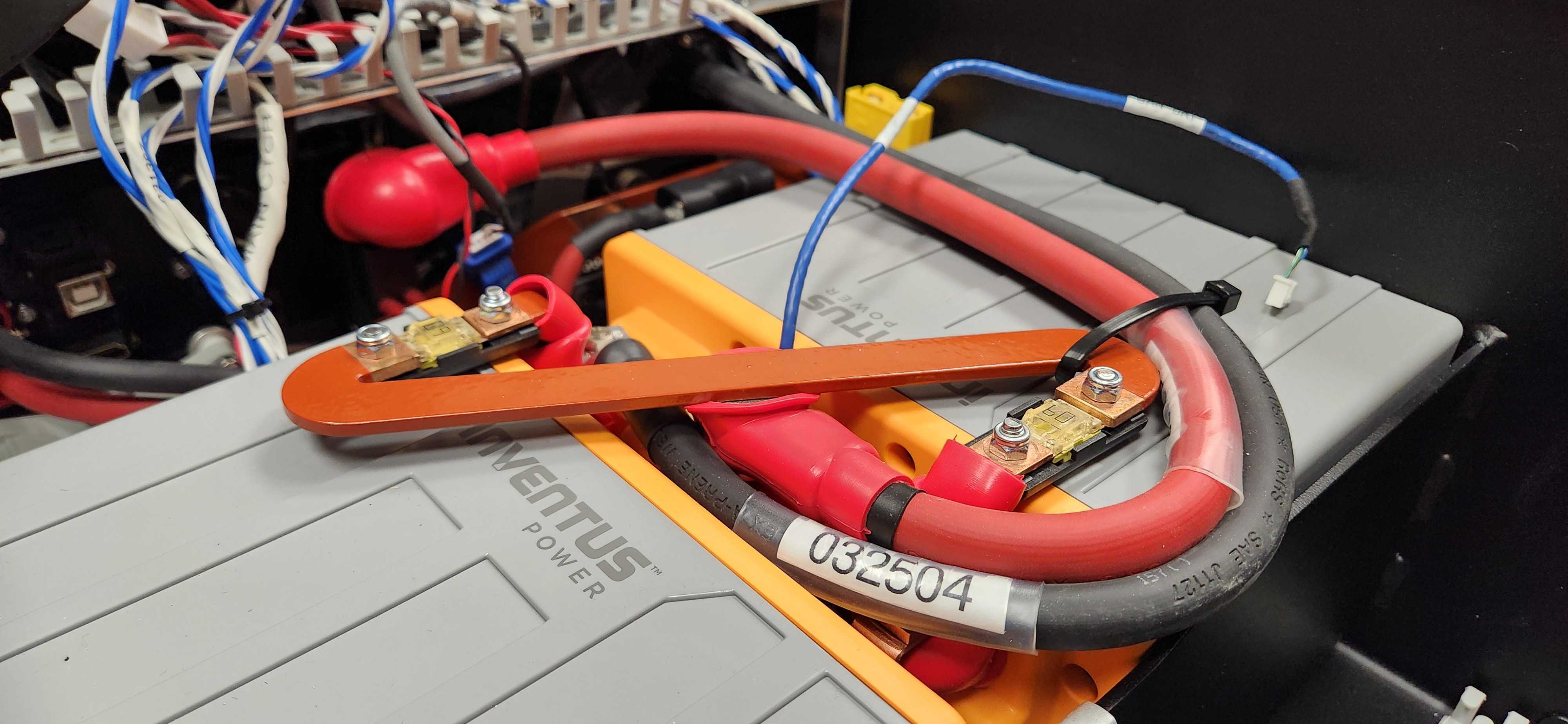
-
Remove the fuse holders's nuts that are holding the red busbar. You may also need to cut a cable tie.
 note
noteWhen reinstalling the busbar:
- Torque the nuts to 3 N·m.
-
Lift the red cable and busbar away from the batteries. The cable will not be live, once it is removed from the fuse holders. The fuses will still be positive voltage.
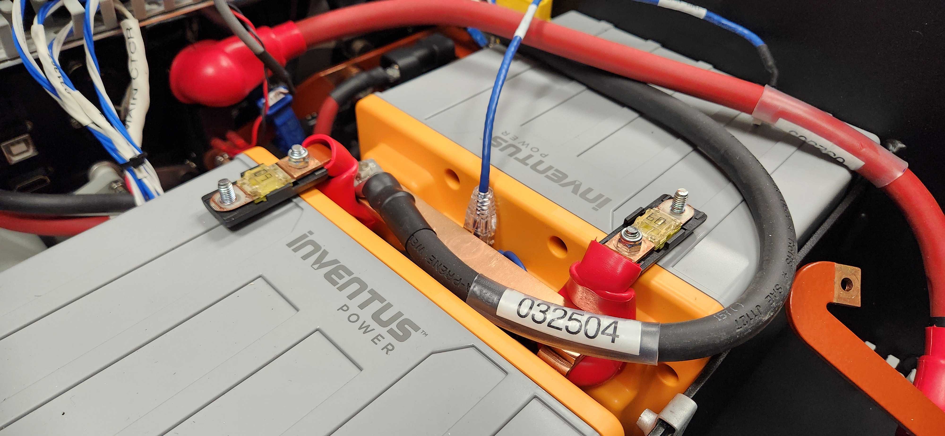
-
Reinstall the fuse holders's covers.
-
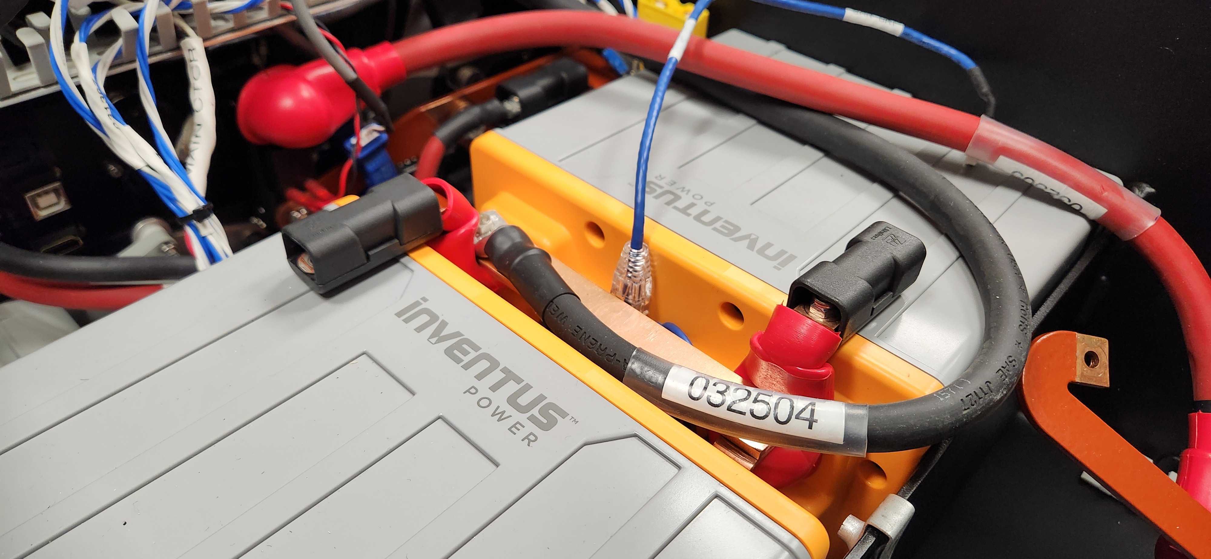
Remove the screw and black cable.
 note
noteWhen reinstalling the cable:
- Torque the screw to 5 N·m.
-
Remove the screw and ground busbar.
 note
noteWhen reinstalling the busbar:
- Torque the screw to 5 N·m.
-
Disconnect the Ethernet / CANbus cable.
-
Lift the batteries out of the robot.
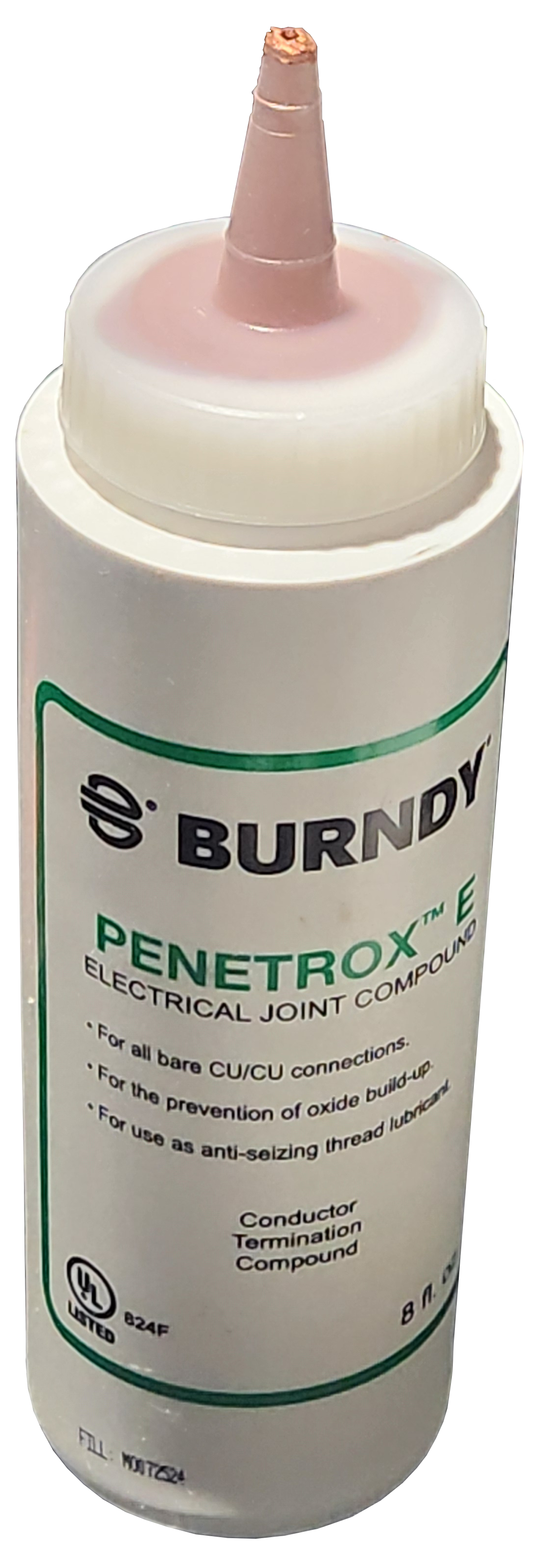
The original Husky A300 builds in 2025 used bare copper busbars. Joints with bare copper surfaces should include Penetrox™ between the mating faces. Excess Penetrox™ can be removed after the joint has been fastened.
Joints with tin-tin contacts do not require Penetrox™.
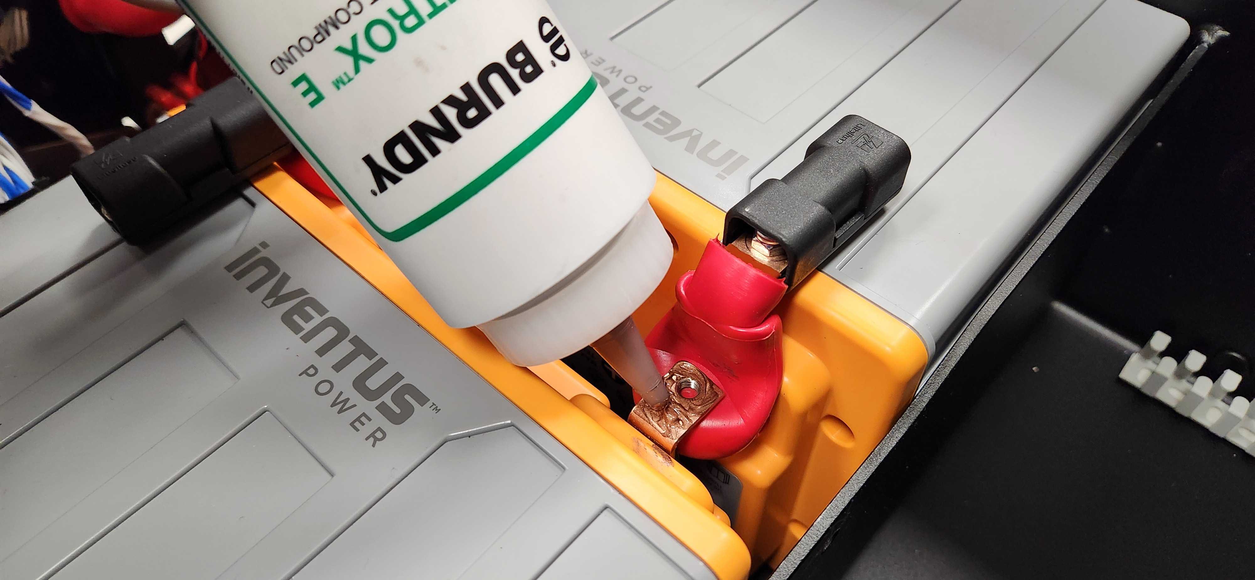
When replacing a battery, only use CPR item 025047 (Inventus S-24V20-U1 battery).
Rear Cover
To remove the Rear Cover
-
Remove the 2 screws and washers.
-
Lift the cover's pins from the chassis's 2 rubber grommets. Keep the Rear Charge Port Door closed while removing the Rear Cover.
When reinstalling the cover:
- Make sure the washers are included with the screws.
- Torque the tray's 2 screws to 2 N·m.
Bumpers
To remove the bumpers:
-
Remove the 2 screws that hold the bumper to the Husky.
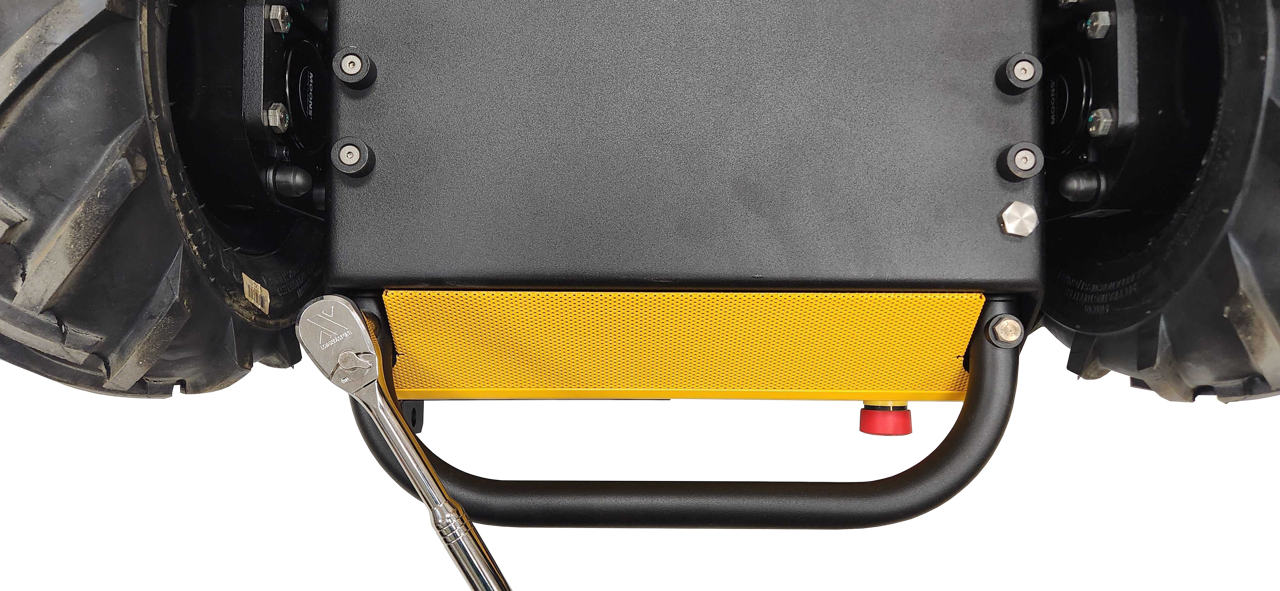
-
Gather the 2 screws, and 4 coped spacers per bumper.
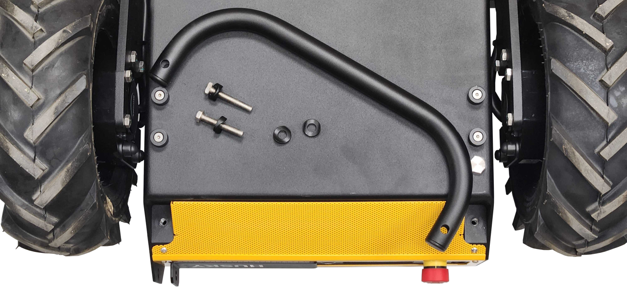
When reinstalling the bumpers:
- Make sure 2 coped spacers are included per screw.
- Torque the screw to 22 N·m.
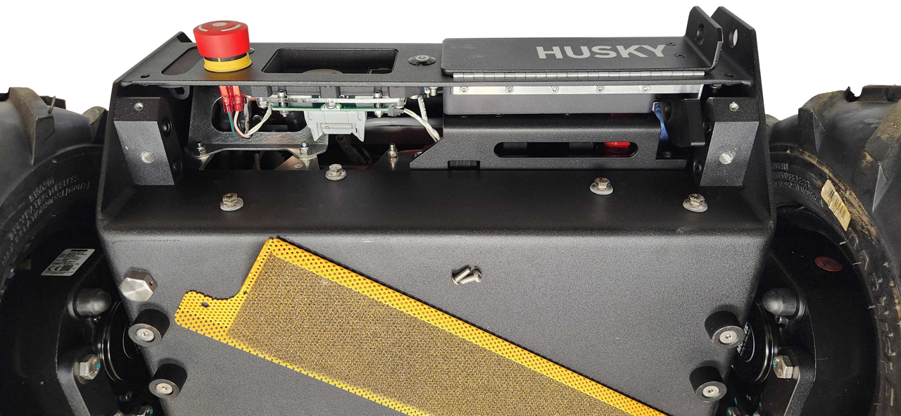
Air Grilles
The front and rear Air Grilles prevent large debris from entering the robot.
To remove the grilles
- Remove the Bumpers.
- Remove the Front Cover and Rear Cover.
- Remove 2 screws per grille.
- Remove the grilles.
When reinstalling the grilles:
- Make sure to include the thin mesh filter on the Rear Air Grille
- Torque the screws to 2 N·m.
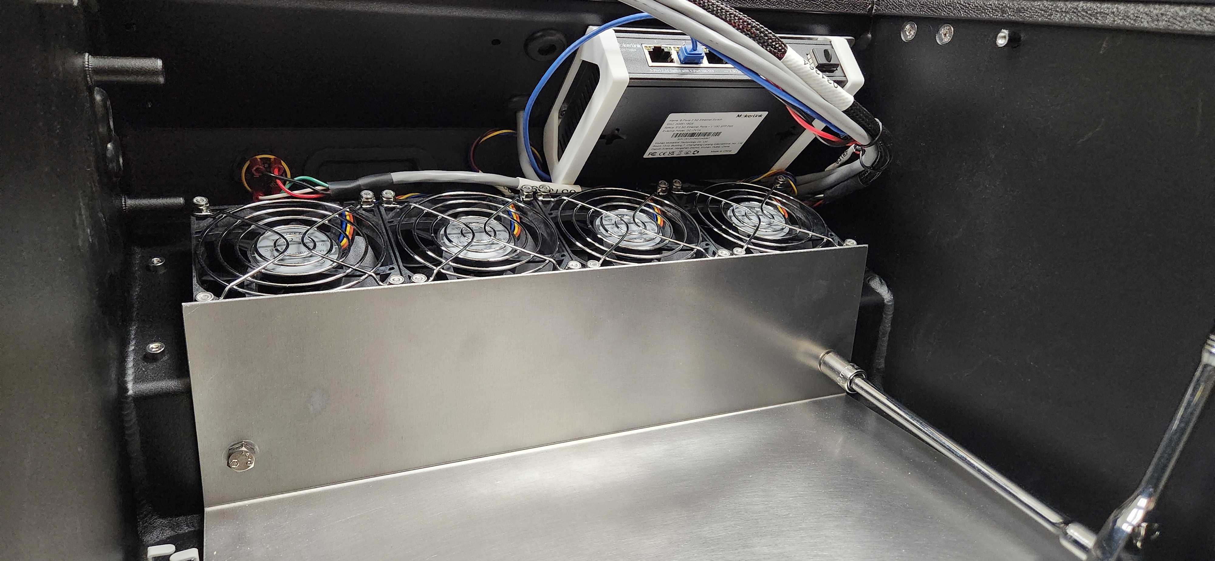
Fans
Husky has 4 fans at the front of the robot. These fans operate similar to a server; as all 4 push air into the robot to create positive pressure inside the chassis.
To remove the fans:
- Turn the robot's circuit breaker off.
- Remove the Top Plate.
- Remove the Front Panel and Air Filter.
- Remove the front Bumper.
- Remove the front Air Grille.
- Use a wrench and hex key to remove the 4 fasteners per fan.
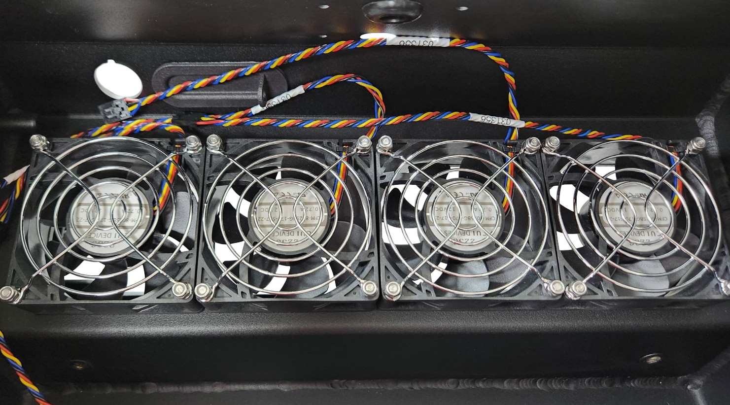
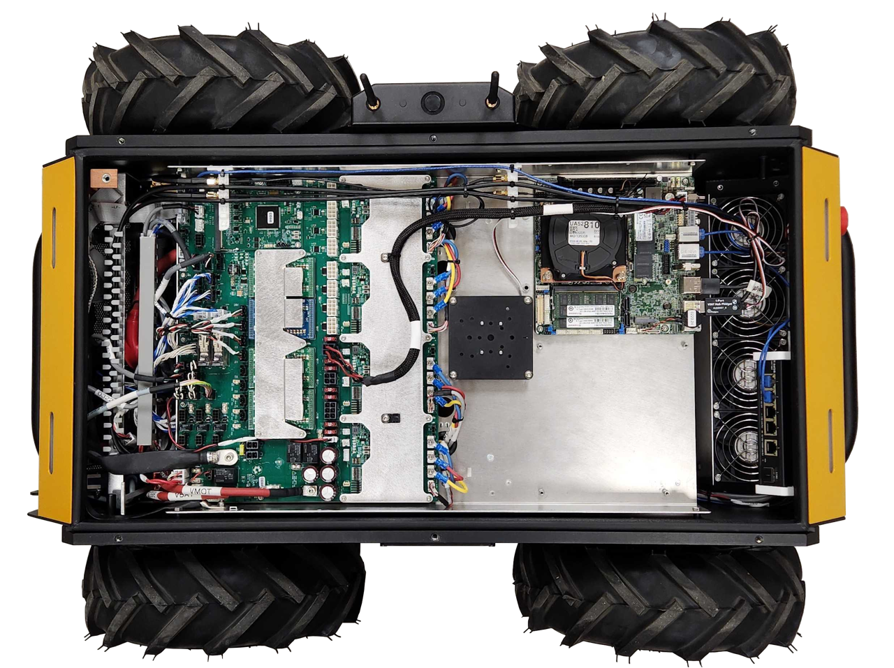
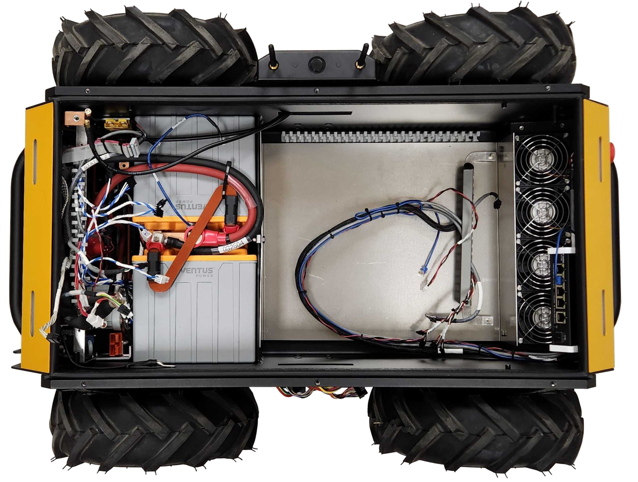
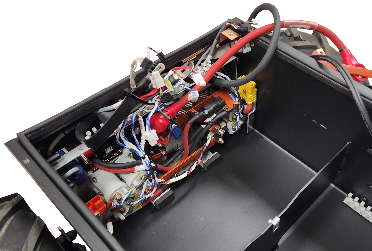
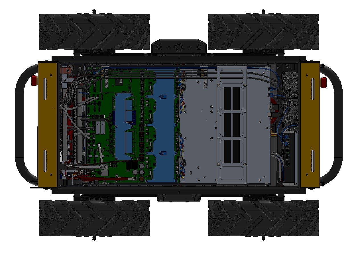
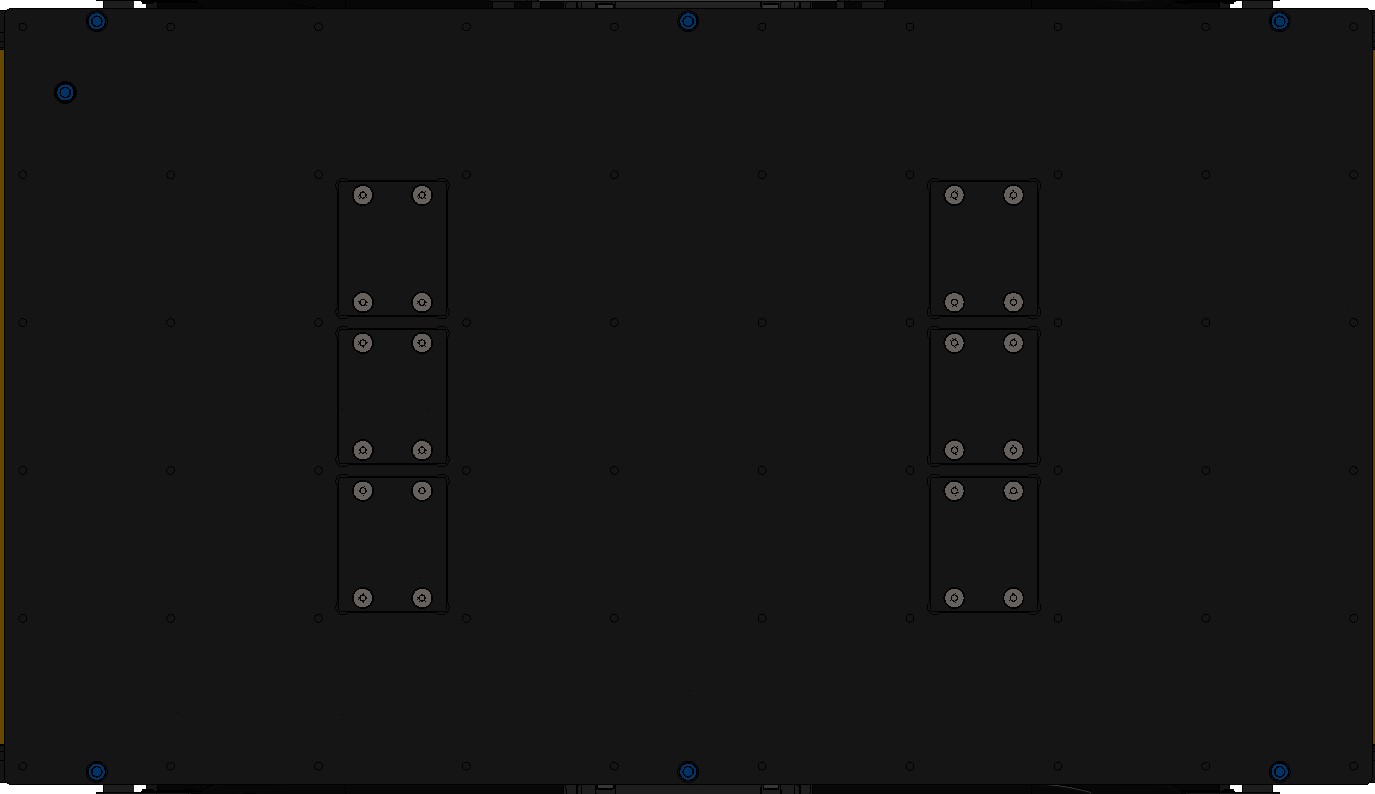
View Inside The Husky's Chassis 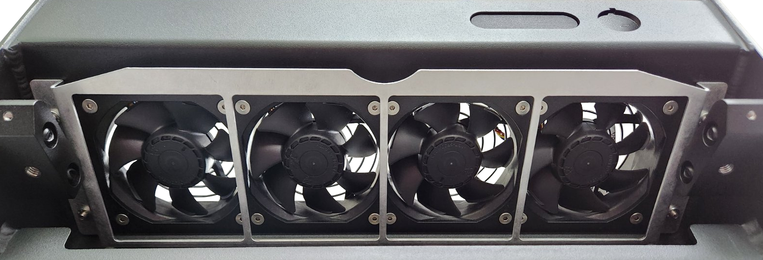
View From The Front Of Husky - Disconnect the fan's latching connector, and remove the fan.
When reinstalling the fans:
- The fan has an arrow on its plastic housing that indicates the airflow direction. Make sure the arrow points into the robot's chassis, to push the air into the robot.
- Fan position 1 is the left / port side of the robot.
- Torque the fans' screws to 2 N·m.
- Make sure to reinstall the Air Filter.
Power Distribution
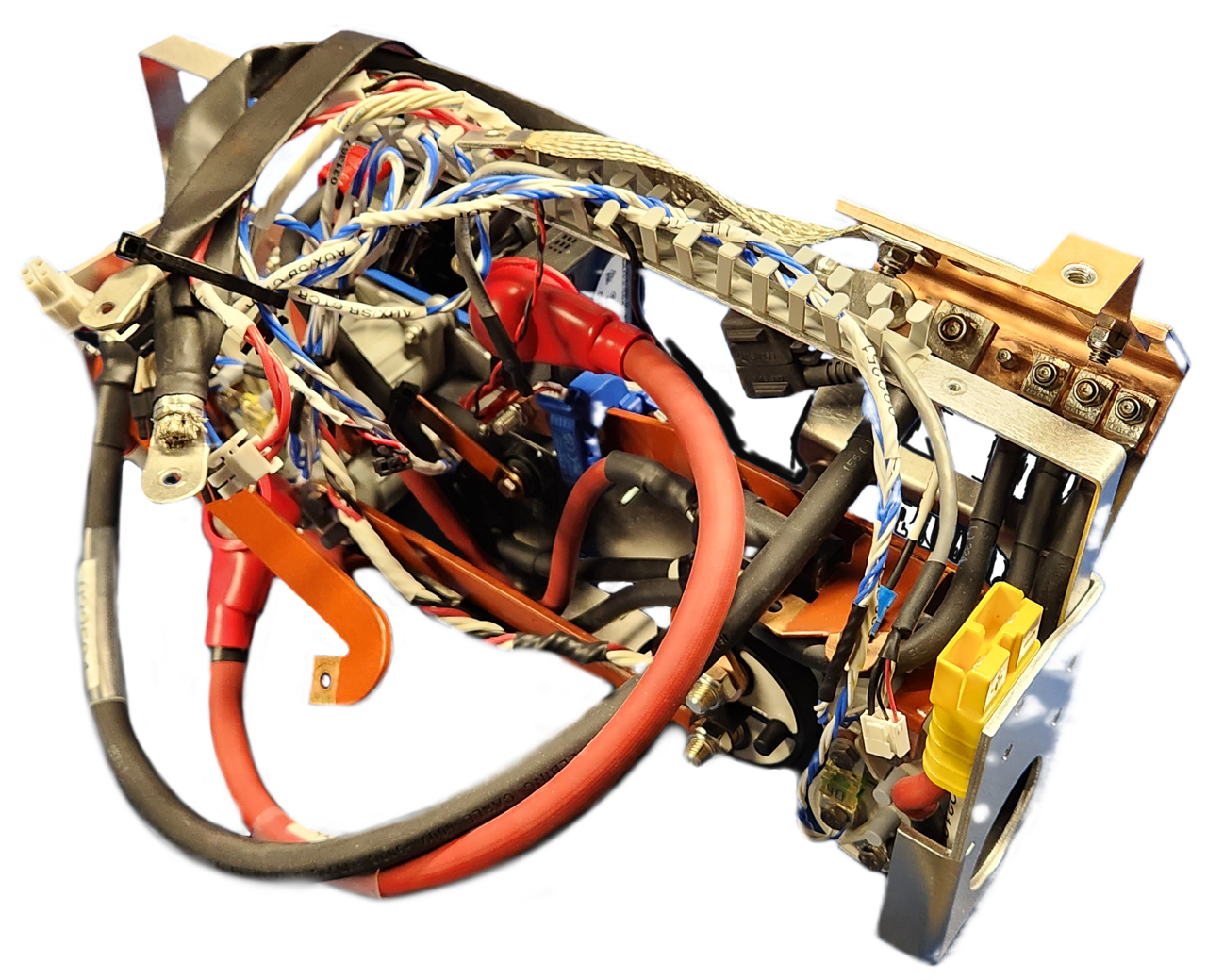
The Power Distribution subassembly includes all the robot's large power electronics:
- Main relay contactor
- Mobility relay contactors
- Shunt brake relay contactors
- Shunt brake resistor
- Large VBAT contactors
- Current sensor
- Circuit breaker
- Fuses
- Busbars, and cables to the batteries
To remove the Power Distribution subassembly:
- Confirm the circuit breaker is in the Off position.
- Remove the Electronics Tray.
- Remove the Rear Bumper, Rear Livery Cover and Rear Air Grille.
- Remove the Power Distribution's 5 screws.
- 1 is above the left Status Light.
- 2 are below the HMI Display.
- 2 are below the Rear Charge Port Door.
- Remove the nut for the bonding braid.
- Pull the Power Distribution assembly forward.
Check that it is not pulling any cables that are still attached to the chassis.
- Remove the Power Distribution from the robot.
When reinstalling the Power Distribution:
- Make sure the sealing washers are still attached to the screws.
- Add a drop of Loctite 243 thread locker to the threads of the screws before installing them.
- Torque the screws to 1.2 N·m.
- Torque the bond braid's nut to 6 N·m.
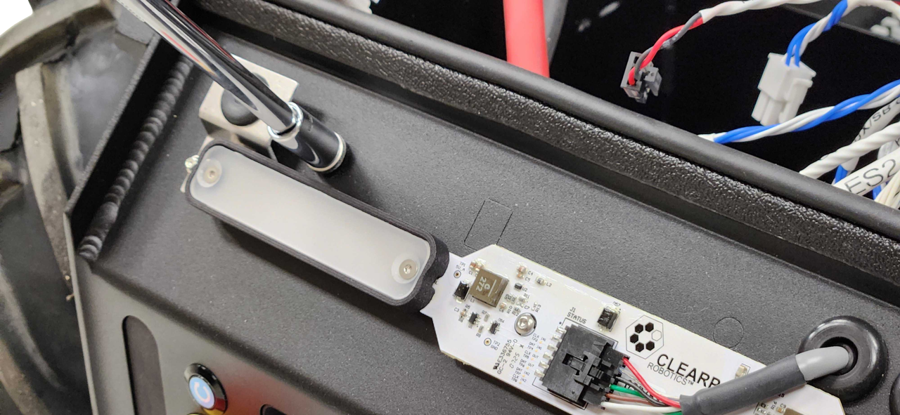
Status Lights
To remove the light assemblies:
- Turn the robot's circuit breaker off.
- Remove the Front Panel.
- Remove the Rear Panel.
- Disconnect the light's cable.
- Remove the 2 nuts that fasten the metal brackets to the chassis.
- Remove the light subassemblies from the robot.
When reinstalling the light assembly:
- Torque each light assembly's 2 nuts to 2 N·m.
To remove the PCBA from the assembly:
- Remove the 2 flat head screws from each of the plastic diffusers.
- Remove the diffusers and cowls.
- Remove the PCBA.
When reinstalling the PCBA:
- Torque each of the diffusers's 2 screws to 0.3 N·m.
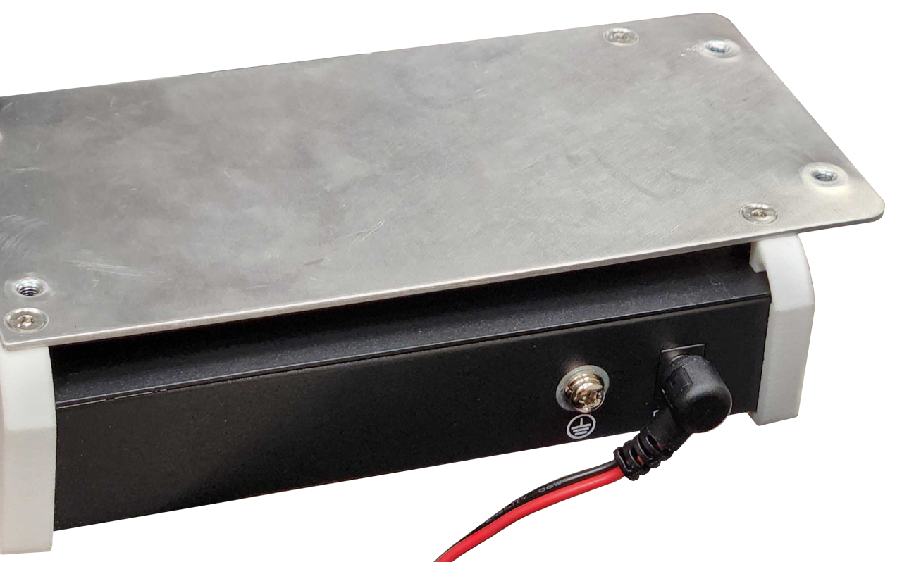
Network Switch
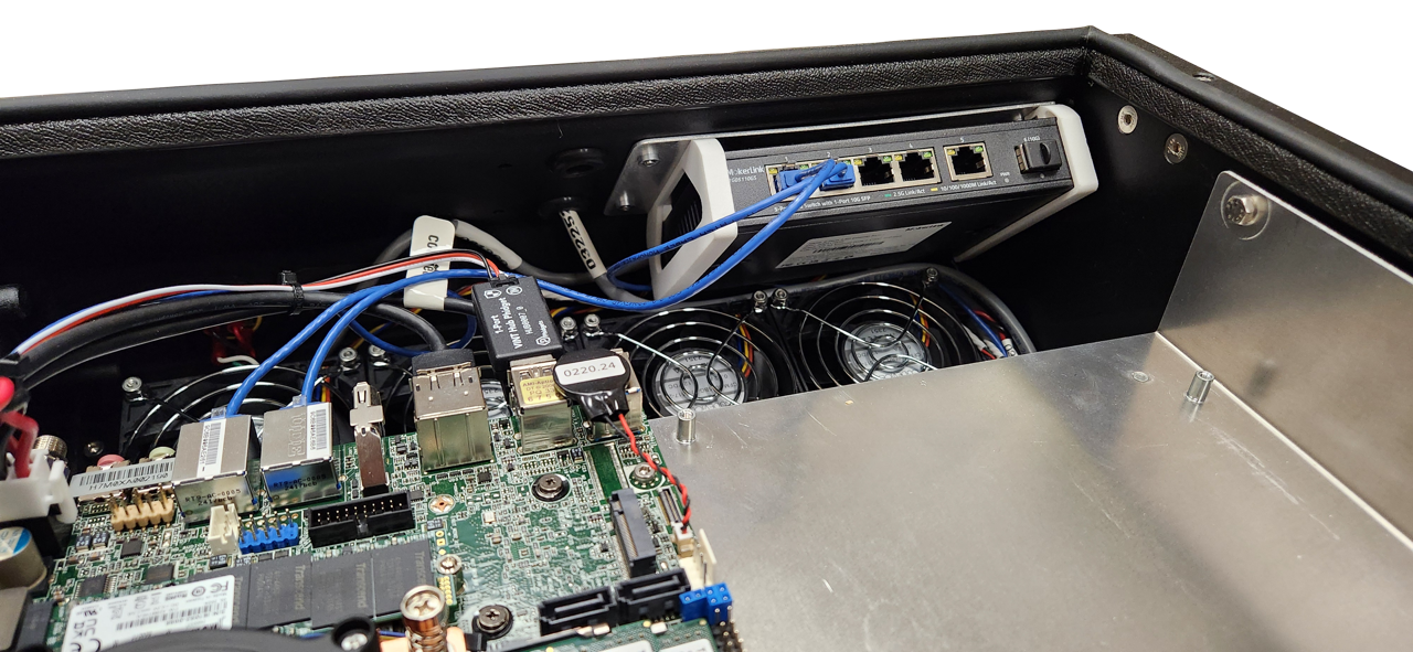
The network switch connects the primary computer, the rear debugging port, and any additional Ethernet devices.
To remove the switch:
- Shut off the robot's circuit breaker.
- Remove Husky's Top Plate.
- Remove any network cables from the switch.
- Remove Husky's Front Panel.
- Remove the 4 screws and waterproofing washers, while holding onto the switch.
- Disconnect the switch's power cable, and remove it from the robot.
When reinstalling the switch:
- Make sure the power cable is connected.
- Make sure the waterproofing washers are included.
- Torque the 4 screws to 1.2 N·m.
To remove the switch from its subassembly brackets:
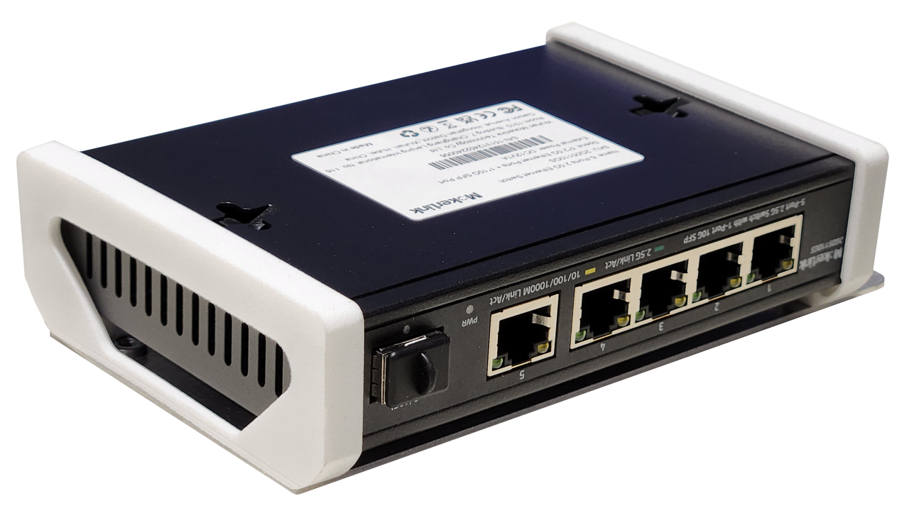
- Remove the 4 flat head screws.
- Remove the switch from the plastic brackets.
When reinstalling the switch:
- Torque the 4 screws to 0.5 N·m.
Computer
There are 2 computer mounting locations on Husky's Electronics Tray. Both mounting locations are sized for Mini-ITX computers.
Clearpath offers a standard computer with an Intel i3 processor, or a performance option with a i7 processor—though custom builds are also an option.
To remove a computer:
- Turn the robot's circuit breaker off.
- Remove Husky's Top Plate.
- Disconnect any cables from the computer:
- USB.
- Ethernet RJ45.
- HDMI.
- Wi-Fi antennas.
- Power cable.
- Optional graphics card's PCIe riser cable.
- Remove the 4 screws fastening the computer to Husky's Electronics Tray.
- Remove the computer from the robot.
When reinstalling the computer:
- Torque the 4 screws to 1 N·m.
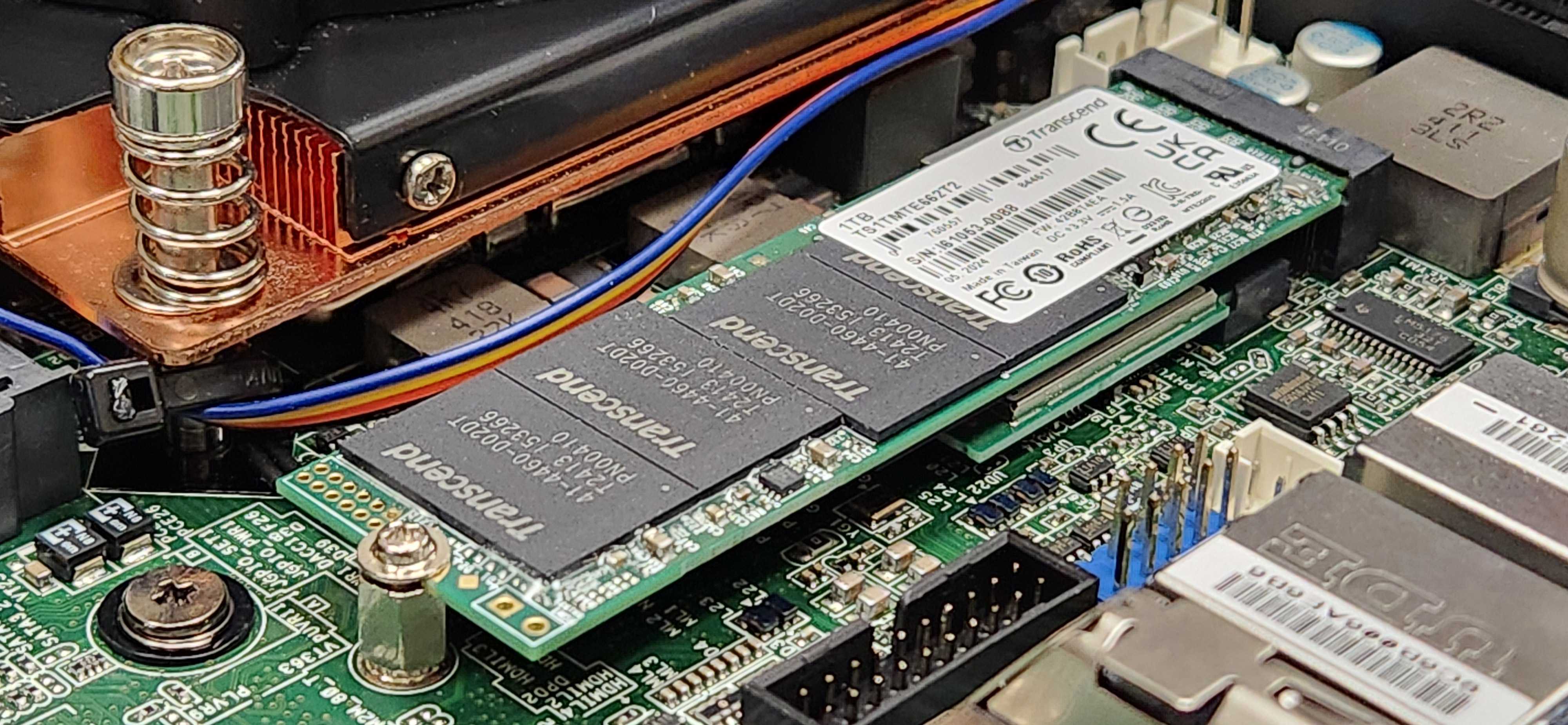
If you are changing the Wi-Fi or Storage M.2 cards:
-
Torque these screws to 0.3 N·m.
Replacing CMOS Battery
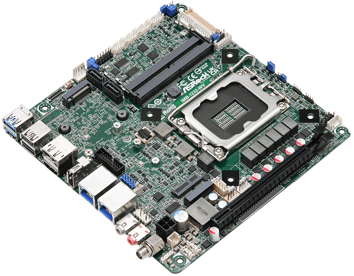
These instructions were developed in 2026 for our robots' mini-ITX computer with a 13th gen intel processor.
Our computers include a CMOS battery to maintain configuration settings while the robot is off. The CMOS battery will recharge whenever the robot is running. The battery typically needs to be replaced after 1 - 2 years.
A common symptom of a depleted CMOS battery is the computer not turning on. Your robot's microcontroller may turn on, so lights and fans may run; but the robot will not drive.
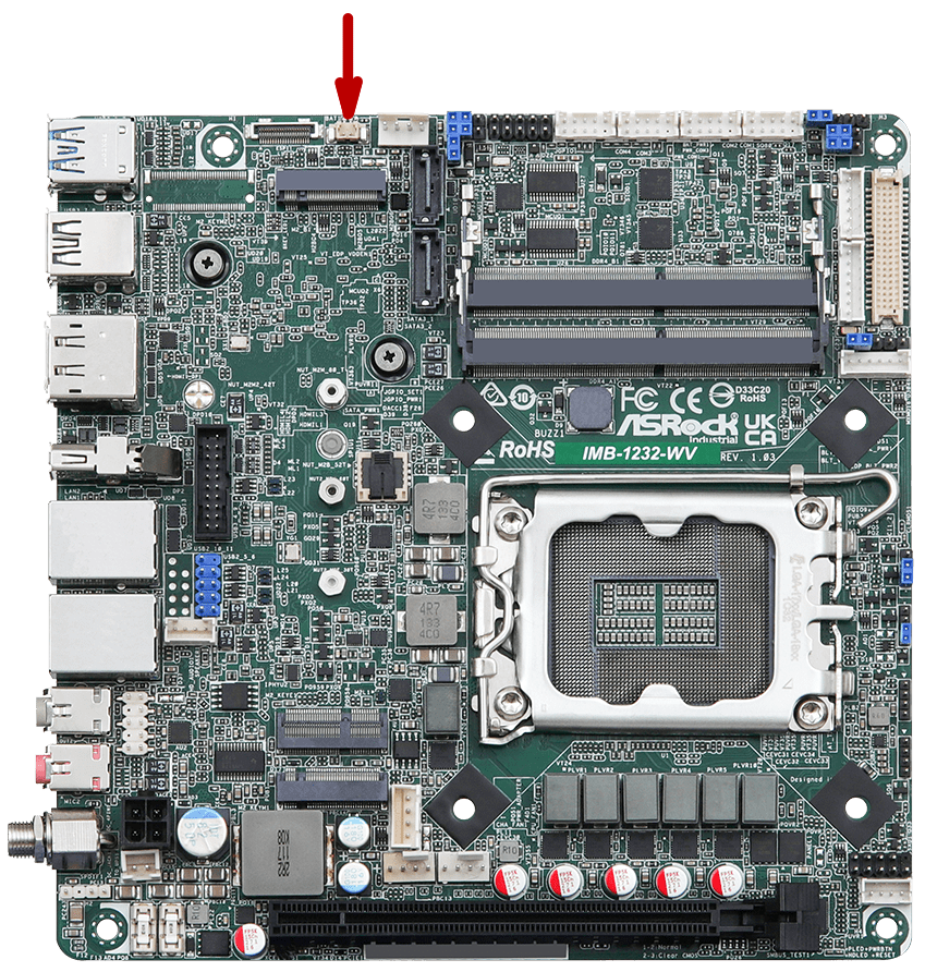
To change the battery:
- Confirm that your robot includes an ASRock Industrial IMB-1232-WV motherboard. Other computer models will include a CMOS battery, but the battery pinout and connector location will be different.
- Get a replacement battery, Clearpath Robotics item 033060.
- Confirm that the replacement battery has the same pinout as the battery you are removing from the robot's computer.
- Remove the old battery.
- Install the new battery, attaching the electrical connector, and mounting the battery with its peel-and-stick pad.
You will need to update the computer's BIOS settings after replacing the battery.
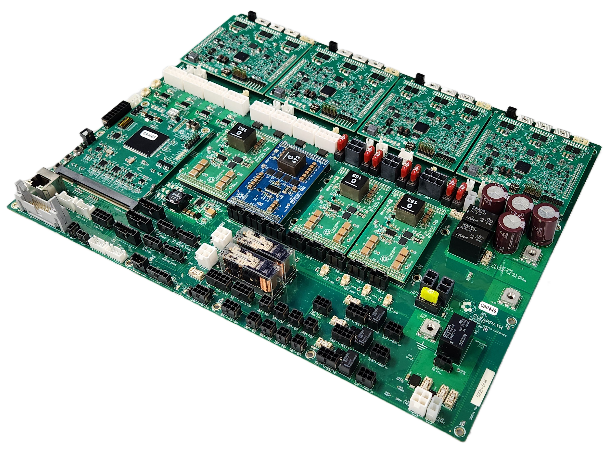
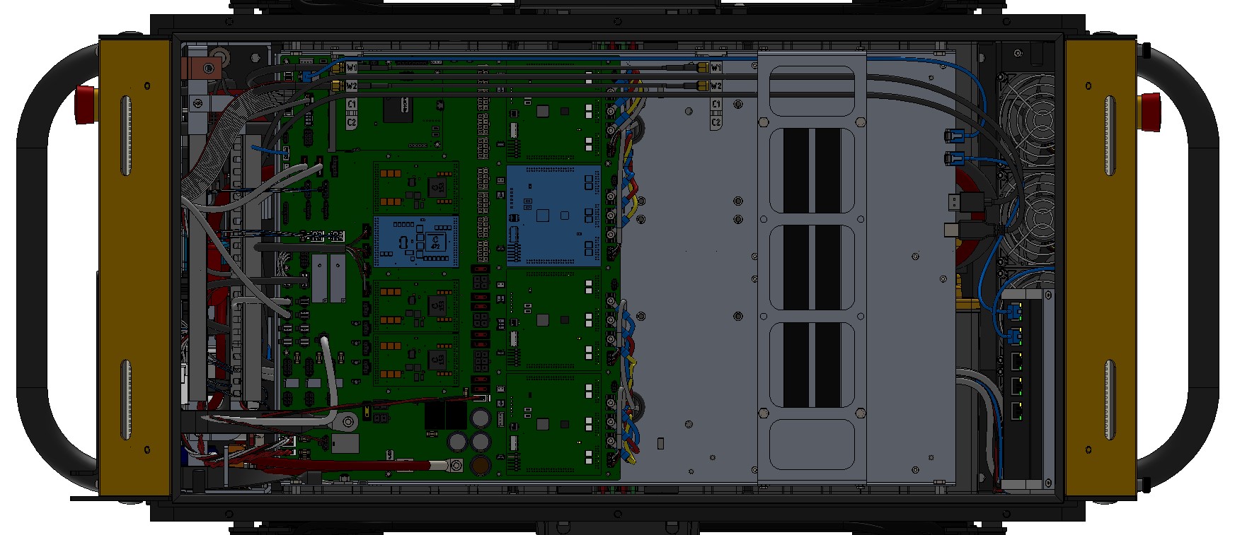
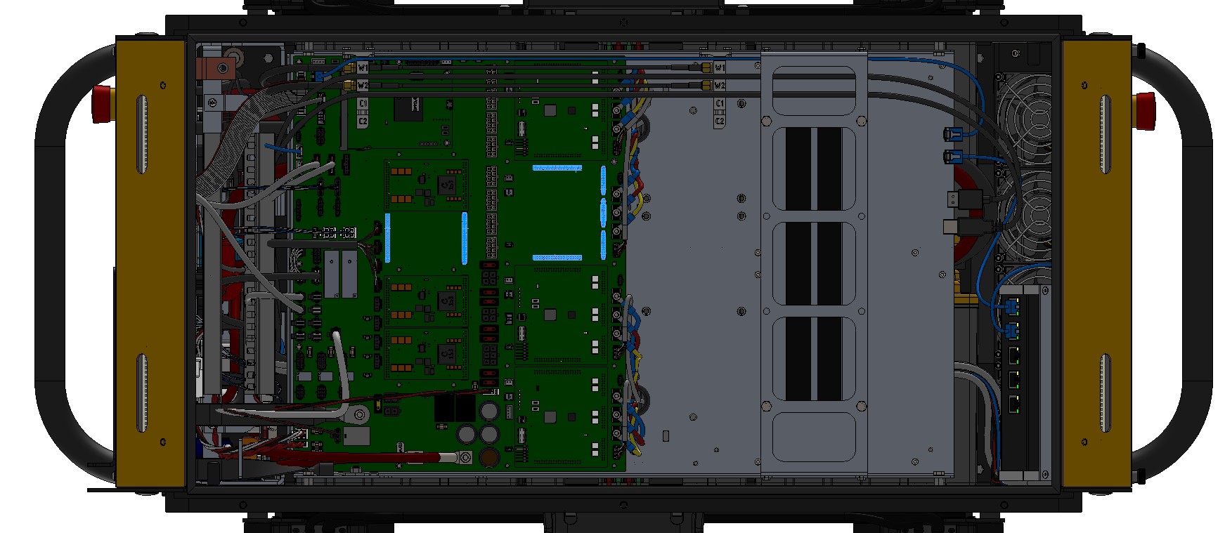
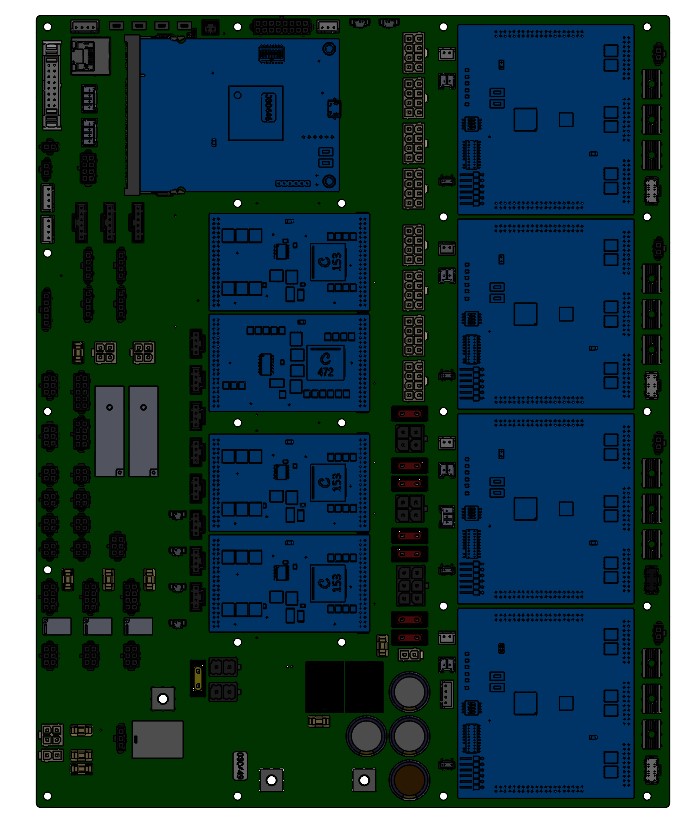
Debugging The System Interface Assembly, (Debug LEDs)
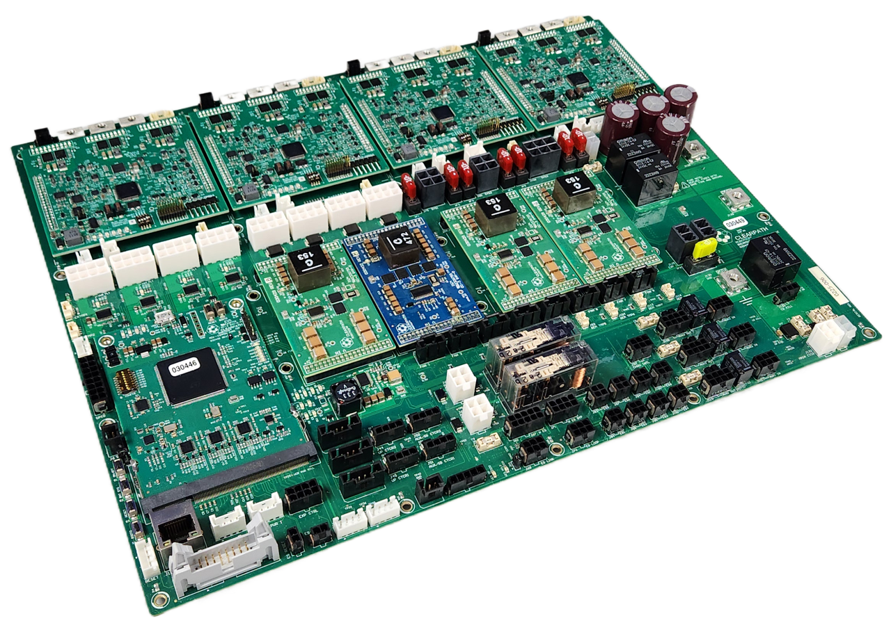
The System Interface Assembly includes many LEDs to help debug system issues.
WARNING
The Husky must be powered on, with the Top Plate removed to see these Debug LEDs. This exposes significant battery energy to the technician, and risk of starting a fire.
Review your worksite's safe operating procedures before performing this task.
Click to see all the LED functions
Common Core Debug LEDs
D6: USB 5V: Solid green if a USB cable is plugged in and used to power the boardD7: 3.3V: Solid green when the 3.3 V power rail is operational; else offD9: DBG/CON: For future useD11: HB/ERR: Heartbeat that toggles (red/off) every 500 ms when the main firmware loop is running; solid on or off indicates an error
DC/DC Debug LEDs
D3: V OUT: Solid green when the output is operational; else off
Motor Controller LEDs
5V0: Solid green when the 5 V power rail is operational; else off3V3: Solid green when the 3.3 V power rail is operational; else offMTR_FAULT: Solid red when a motor fault is detected; else offERROR: Toggles (red/off) every 500 ms when a motor control error is detected; else offDBG2: For future useDBG1: Heartbeat that toggles (green/off) every 500 ms when the firmware loop is running; solid on or off indicates an error
Main Circuit Board Debug LEDs
D2: UVB FLT: User power VBAT fault: red if the user battery rail is not enabled or if there has been a fault such as an overcurrent or over temperature event; else offD3: U24 FLT: User power 24V fault: red if the user 24V rail is not enabled or if there has been a fault such as an overcurrent or over temperature event; else offD4: U12A FLT: User power 12VA fault: red if the user 12VA rail is not enabled or if there has been a fault such as an overcurrent or over temperature event; else offD5: U12B FLT: User power 12VB fault: red if the user 12VB rail is not enabled or if there has been a fault such as an overcurrent or over temperature event; else offD6: PWR GD: Main power good indicator: red if any power supply is not enabled or has a fault; else offD7: 3.3V: Solid green if 3.3V rail is operational; else offD9: UPWR GD: User power good indicator: red if any of the 4 user power rails are not enabled or have a fault (including and overcurrent on any channel); else offD10: 5V: Solid green if 5V rail is operational; else offD12: APWR GD: Auxiliary power good indicator: red if either of the auxiliary power supplies are not enabled or has a fault (Auxiliary power supplies the USER power as well as other PCBA subsystem power rails at 12V and 24V); else offD13: SPWR GD: System power good indicator: red if either of the system power supplies are not enabled or has a fault (System power supplies the power for PCs, any optional GPU, and the primary network switch); else offD30: WES BP: Wireless E-Stop Bypass indicator: green if the Wireless E-Stop Bypass is enabled; else offD31: WES PFLT: Wireless E-Stop Power fault: red if the power supply is not enabled or has a fault; else offD46: XPWR GD: Expansion power good indicator: red if expansion power is not enabled or has a fault; else off
Replacing Circuit Boards
Husky has several circuit boards—(PCBAs). It is uncommon for a PCBA to fail during operation, but could occur from physical damage during a maintenance task. If a failure occurs, usually only one board needs to be replaced, rather than the full System Interface Assembly.
PCBAs are sensitive components and can be damaged easily through electrostatic discharge—(ESD). Be sure to follow proper ESD protection measures prior to handling any circuit boards.
WARNING
Confirm that Husky's Emergency Stop System is functioning after changing any of the circuit boards.
Procedure for replacing the DC-DC and BLDC circuit boards
-
Turn off the robot's circuit breaker.
-
Remove the 7 screws that fasten the Top Plate to the chassis and remove the Top Plate.
-
Remove the cable brush holder.

-
Remove the heat shield covering the DC-DC or BLDC circuit boards.
-
Remove the failing circuit board by gently lifting the board up. These circuit boards have many pins, so a large amount of force is required.
-
Install the new circuit board by aligning the connector and gently sliding it into place.
-
Reinstall the heat shields.
-
Reinstall the cable brush holder.
-
Put the Top Plate back in place and finger tighten the 7 screws. Note that the screw with the sealing washer goes in the inner location, and the remaining 6 screws are installed around the perimeter. Tighten all screws to 3 N·m.
Procedure for replacing the Common Core circuit board
-
Turn off the robot's circuit breaker.
-
Remove the 7 screws that fasten the Top Plate to the chassis and remove the Top Plate.
-
Remove the Common Core by removing the 2 retaining screws, pushing out on the retaining clips, and then gently pulling the board out horizontally.
-
Install the new circuit board by gently sliding it into place horizontally, ensure that the retaining clips are secured, and that the two screws have been installed.
-
Put the Top Plate back in place and finger tighten the 7 screws. Note that the screw with the sealing washer goes in the inner location, and the remaining 6 screws are installed around the perimeter. Tighten all screws to 3 N·m.
Procedure for replacing the Main circuit board
-
Turn off the robot's circuit breaker.
-
Remove the 7 screws that fasten the Top Plate to the chassis and remove the Top Plate.
-
Disconnect all cables from the Main circuit board.
-
Remove the Main circuit board by removing the screws and then lifting out the board.
-
Place the old and new Main circuit boards on an ESD mat.
-
Move the functional DC-DC, BLDC, and Common Core circuit boards from the old Main circuit board to the new Main circuit board by following the procedures above.
-
Install the new Main circuit board tighten the retaining screws to 1 N·m.
-
Reconnect all cables, noting that the labels on the cables should match those on the board.
-
Put the Top Plate back in place and finger tighten the 7 screws. Note that the screw with the sealing washer goes in the inner location, and the remaining 6 screws are installed around the perimeter. Tighten all screws to 3 N·m.
Replacing Board Mount Fuses
- Perform the Lockout-Tagout Procedure.
- Locate the fuse to be replaced. Follow the maintenance procedures for the corresponding
subassembly to access the fuse.

CAUTION
Treat all circuits, cables, and fuses inside the robot as potentially live.
Some connections inside the robot are live even after Lockout Tagout. Refer to the details of the subassembly maintenance procedures to determine if the fuse is connected to a live connection. - Use tweezers to pull up on the old fuse to remove it from the fuse holder.
- Slide the replacement fuse into the fuse holder and push firmly until the fuse is installed fully.
note
Ensure that you are replacing the fuse with the same part number and rating. Refer to Common Replacement Items for a list of fuses.
Replacing Mini Blade Fuses
- Perform the Lockout-Tagout Procedure.
- Locate the fuse to be replaced. Follow the maintenance procedures for the corresponding
subassembly to access the fuse.
CAUTION
Treat all circuits, cables, and fuses inside the robot as potentially live.
Some connections inside the robot are live even after Lockout Tagout. Refer to the details of the subassembly maintenance procedures to determine if the fuse is connected to a live connection. - Pull up on the old fuse to remove it from the fuse holder.
- Slide the replacement fuse into the fuse holder and push firmly until the fuse is installed fully.
note
Ensure that you are replacing the fuse with the same part number and rating. Refer to Common Replacement Items for a list of fuses.
Replacing BF1 Fuses
- Perform the Lockout-Tagout Procedure.
- Locate the fuse to be replaced. Follow the maintenance procedures for the corresponding
subassembly to access the fuse.
CAUTION
Treat all circuits, cables, and fuses inside the robot as potentially live.
Some connections inside the robot are live even after Lockout Tagout. Refer to the details of the subassembly maintenance procedures to determine if the fuse is connected to a live connection. - Remove the fuse cover.
- Remove the nuts holding the fuse in place.
- Remove the fuse from the fuse holder.
- Install the replacement fuse into the fuse holder.
note
Ensure that you are replacing the fuse with the same part number and rating. Refer to Common Replacement Items for a list of fuses.
- Reinstall both nuts onto the fuse holder and tighten to 3 N·m unless otherwise specified in the subassembly maintenance procedures.
- Reinstall the fuse cover.
Software Maintenance
Getting New Packages
If you are upgrading your robot from an older version of ROS, please refer to our upgrade instructions for upgrading to ROS 1 Melodic, ROS 1 Noetic and ROS 2.
Clearpath Robotics robots are always being improved, both its own software and the many community ROS packages upon which it depends!
You can use the apt package management system to receive new versions all software running on the platform.
Use the apt command for package management commands in this guide.
Each robot leaves the factory already configured to pull packages from http://packages.ros.org as well as http://packages.clearpathrobotics.com. To update your package and download new package versions, simply run:
sudo apt update
sudo apt full-upgrade
MCU Firmware Update
Refer to firmware update instructions. Be sure to select the ROS 2 distribution that matches the ROS 2 distribution installed on your robot.
Motor Controller Firmware Update
Use the following command to update the firmware on the motor controllers, using the serial number
of your robot rather than xxxxx.
Do NOT power off the robot while this command is running. The update typically takes a few minutes to complete for all four motor controllers.
ros2 action send_goal /a300_xxxxx/platform/motors/update clearpath_motor_msgs/action/LynxUpdate {} -f
What to Expect
The update is implemented as a ROS 2 action, so the command will stream feedback while it runs and then print a final result. Both pieces of output are normal and should be reviewed to confirm a successful update.
Feedback (during the update)
While the update is in progress, the action publishes a Feedback message containing a progress array, with one
entry per motor controller (front-left, front-right, rear-left, rear-right). Each value is the percentage of the
firmware image that has been transferred to that controller (0.0 - 100.0). A typical feedback block looks like:
Feedback:
  progress:
  - 100.0
  - 100.0
  - 100.0
  - 99.0
The values increment as each controller is flashed and will end at 100.0 for every controller that updated
successfully. It is normal to see one controller briefly lag behind the others.
Result (when the update finishes)
When the action completes, a Result message is printed with a success array, again with one entry per motor
controller, in the same order as the feedback progress array. A true value means that controller was
re-flashed with the new firmware; a false value means that controller was already running the target firmware
version (or did not need to be updated) and was therefore skipped. The action itself reports
Goal finished with status: SUCCEEDED in both cases; false entries are not an error.
Result:
  success:
  - false
  - false
  - false
  - false

Goal finished with status: SUCCEEDED
The example above is what you will see if all four motor controllers are already on the latest firmware: the action succeeds, but no controller actually needed to be reflashed.
If the action exits with a status other than SUCCEEDED, or if any feedback progress entry stops increasing
and never reaches 100.0, contact Clearpath Support.
Once the action has completed, power cycle the robot for the new firmware to take effect.
Motor Controller Calibration
The motor controllers are configured in the factory and do not normally need to be reconfigured in the field.
If you have been instructed by Clearpath Support to recalibrate, place the robot up on blocks so that the
wheels do not touch the ground, and then use the command below, using the serial number
of your robot rather than xxxxx.
Do NOT power off the robot while this command is running.
Ensure that the robot does not have its Emergency Stop engage while running this command.
Ensure that the robot is up on blocks so that the wheels do not touch the ground and can spin freely.
ros2 action send_goal /a300_xxxxx/platform/motors/calibrate clearpath_motor_msgs/action/LynxCalibrate {} -f
Support
Clearpath is committed to your success. Please get in touch with us and we will do our best to get you rolling again quickly: support@clearpathrobotics.com.
To get in touch with a salesperson regarding Clearpath Robotics products, please email research-sales@clearpathrobotics.com.
If you have an issue that is specifically about ROS and is something which may be of interest to the broader community, consider asking it on Robotics Stack Exchange. If you do not get a satisfactory response, please ping us and include a link to your question as posted there. If appropriate, we will answer on Robotics Stack Exchange for the benefit of the community.