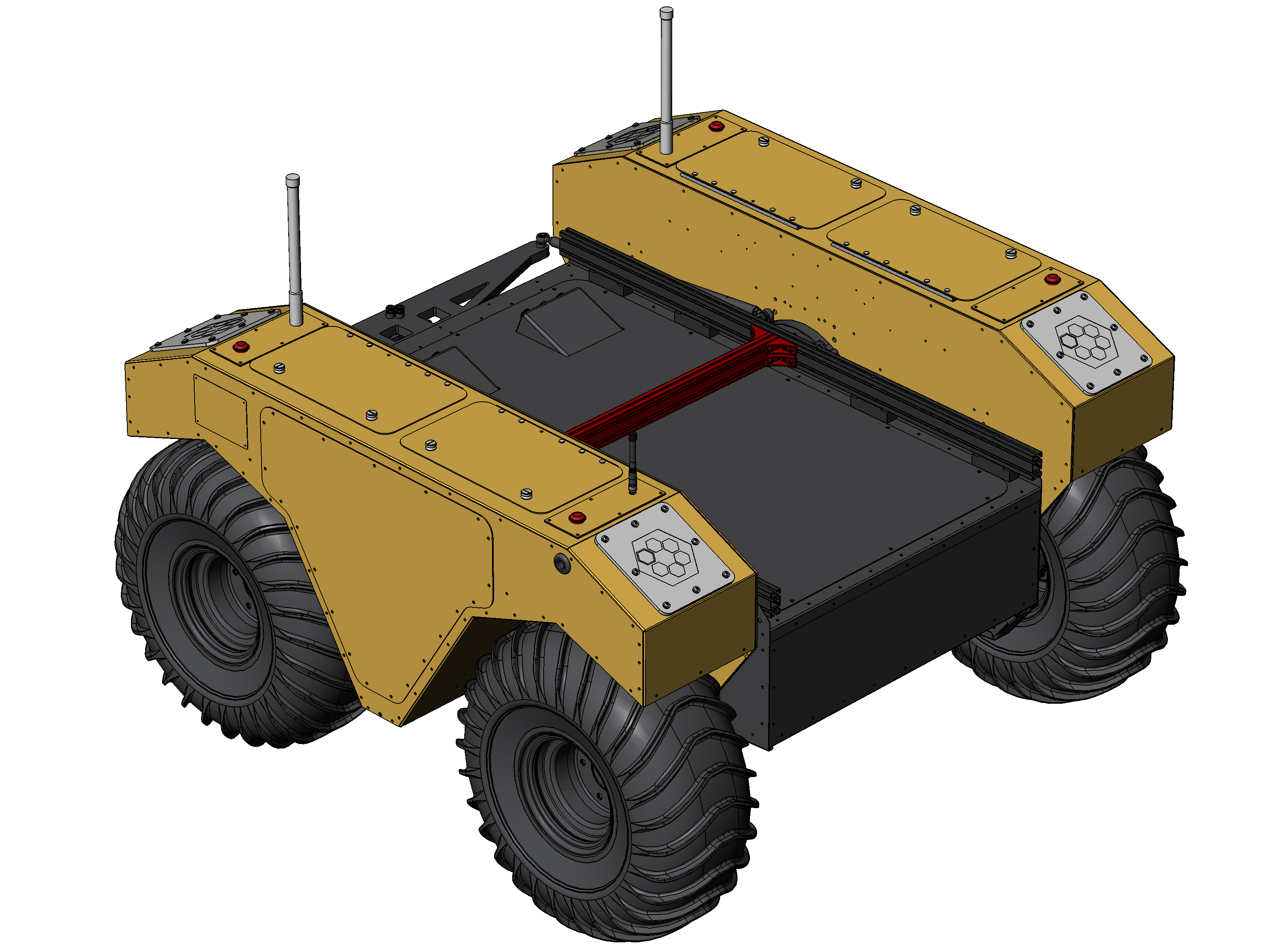
Extrusion Cross-Bar

This is a 25 mm X 50 mm aluminum extrusion that mounts between the Warthog's Extrusion Rails. The Cross-Bar is installed with T-slot nuts and 90° brackets. The Cross-Bar can be attached anywhere along the length of the Warthog's Extrusion Rails.
Sales Kits
This kit requires a Warthog with Extrusion Rails. Refer to the Extrusion Rails page for further details.
| Description | Sales Kit |
|---|---|
| Installation—Extrusion Cross-Bar, 25 X 50, 652 | 028455 |
Parts List
| ID | Description | CPR item | Quantity |
|---|---|---|---|
| 1 | Beam, T-slot—25 X 50, 655, Aluminum, Black | 028465 | 1 |
| 2 | Bracket, T-Slot, 90°—5.8, 20, Aluminum, Black | 028464 | 8 |
| 3 | Nut, T-Slot—M5×0.8 X 5.8 X 10, Steel | 028463 | 32 |
| 4 | Screw, Cap, Socket Head—M5×0.8 X 10, Stainless Steel | 023150 | 32 |
Tools required
- Hex Key, 4 mm
- Torque wrench (optional, for safety applications)
- Loctite 243 (optional, for high vibration applications)
Installation
Step 1
Attach 8 Brackets (ID2) to the ends of the Beam (ID1). Use 2 T-slot Nuts (ID3) and 2 Screws (ID4) per Bracket.
Torque these screws to 5 N·m if you are concerned about them loosening from high vibration applications.
You may add a small amount of thread locker to these screws if you are concerned about them loosening from high vibration applications.
Step 2
Add a T-slot Nut (ID3) and Screw (ID4) to each of the remaining holes of the Brackets (ID2). Leave these Screws loose, in anticipation of the next step.
You may add a small amount of thread locker to these screws if you are concerned about them loosening from high vibration applications.
Step 3
Slide the Cross-Bar assembly between the Warthog's Extrusion Rails. Make sure all 16 of the loose T-slot nuts are guided into the Extrusion Rails.
Step 4
Slide the Cross-Bar assembly to your intended final position on the Warthog per your application.
Step 5
Tighten all 16 Screws.
Torque these screws to 5 N·m if you are concerned about them loosening from high vibration applications.