Husky A300 Integration
CAUTION
Always perform a risk assessment prior to any custom integrations.
Custom integrations are outside the scope of the base robot's safety assessment and custom integrations may result in new hazards.
To attach custom hardware to Husky, you will have to take care of mechanical mounting, electrical supply, and software integration. This guide aims to equip you with respect to these challenges.
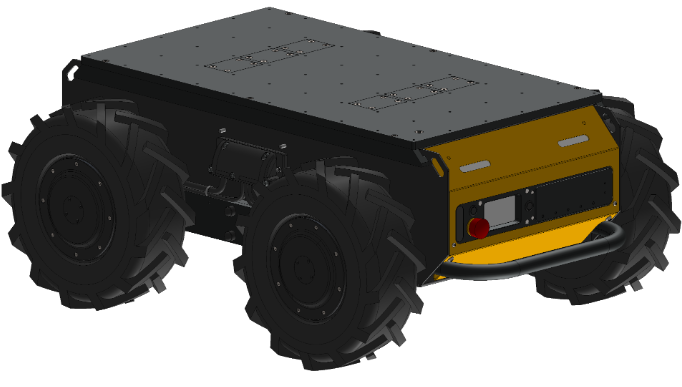
Mechanical Mounting
STEP Model
base_link
base_link is the primary coordinate system for the robot.
All sensors, manipulators, and brackets are positioned with reference to base link.
This ROS 2 Documentation page explains how a robot's model is constructed.
Husky's model is included on the robot, and is available on our public GitHub.
Husky's base_link is located on the bottom of the chassis, with +X pointed toward the front panel, and +Y toward the robot's left side.
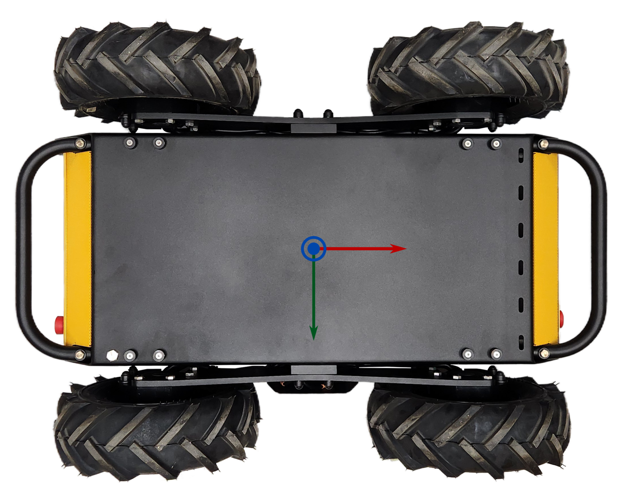
The STEP Model's origin is aligned with base_link.
PACS™ Mounting and Kits
Husky A300 is equipped with a PACS™ Top Plate for mounting sensors and equipment. PACS™ is a Clearpath Robotics standard, providing a grid of M5×0.8 holes onto the Top Plate of the robot. This grid of holes has a 80 mm X 80 mm spacing. You can create your own brackets to interface with these holes, or can use an existing Clearpath Robotics bracket.
Cable Passthrough
To maintain Husky's IP54 rating while allowing cables to pass between the external kits and internal electronics, Husky's top plate is provisioned with expansion plates for cable IP rated cable systems. There are three expansion plates at the front, and three at the rear of the top plate.
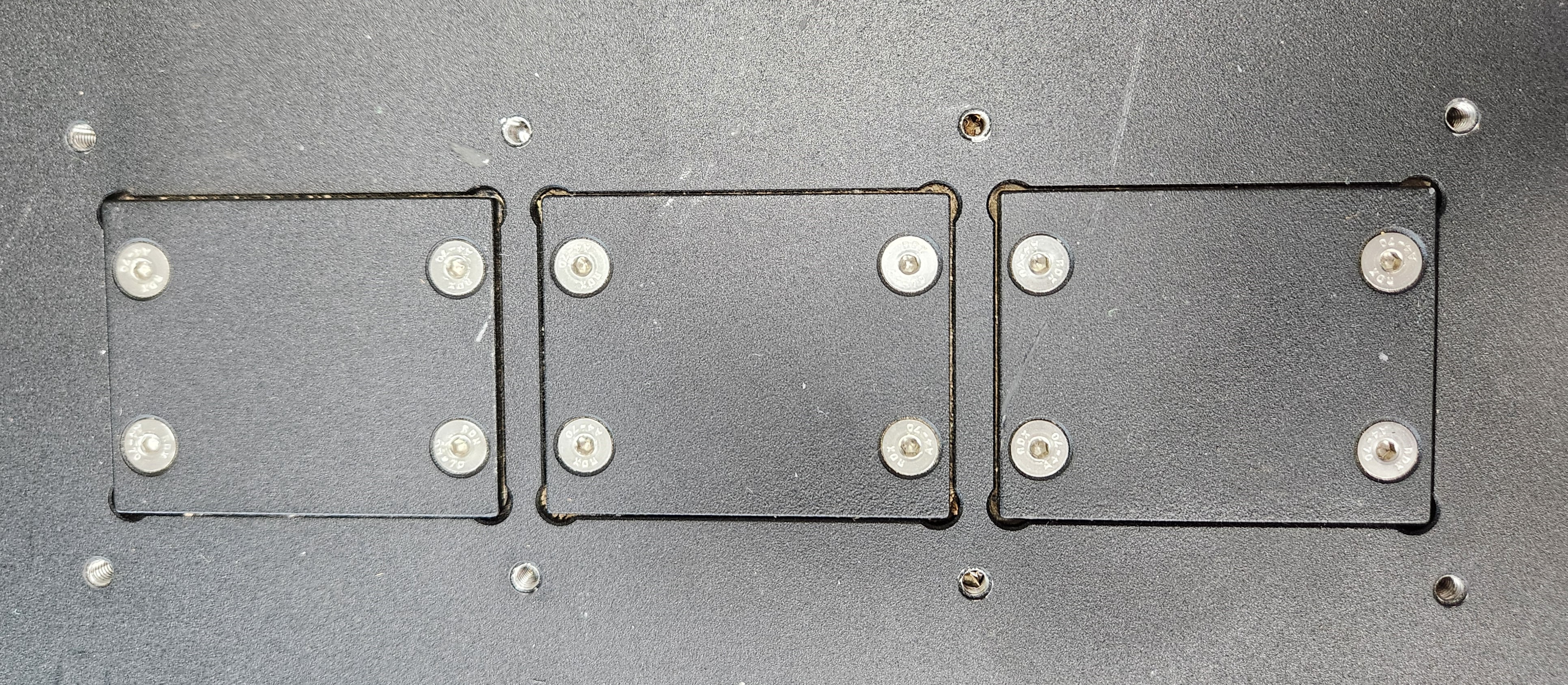
Technicians have two main options.
- Drill holes in the expansion plates and add appropriate IP-rated sealing solutions on a cable-by-cable basis.
- Remove an expansion plate and replace it with a cable entry system, such as Icotek.
Using the Icotek Cable Entry System
The Icotek Cable Entry System allows pre-terminated cables up to 65 mm in diameter to be routed into Husky A300, and be sealed with up to IP66 rated ingress protection. In addition, the cable entry frames serve as strain relief on the cable.
This cable system is based on a set of cable entry frames and grommets. Refer to the demonstration video for an overview of using the system.
Supported cable entry frames:
| Clearpath Item | Description | Manufacturer Item |
|---|---|---|
| 031161 | Blank Plate |
|
| 032256 | Gasket |
|
| 031682 | Straight Icotek Housing | |
| 032777 | 90° Icotek Housing Kit |
|
| 028997 | 360° Icotek Housing Kit |
|
Supported grommets:
Grommets are selected based on the size of the cable being passed through. A list of the most common grommets are listed in the table below. Also review Icotek's full grommets catalog.
| Part Number | Part Description | CPR Item Number | Retailer Link |
|---|---|---|---|
| Blank BK (41351) | Blank grommet | 031393 | RS-Online |
| KT 1 BK (39943) | 1X Split grommet for 1 - 2 mm cable | N/A | RS-Online |
| KT 2 BK (41302) | 1X Split grommet for 2 - 3 mm cable | 032027 | RS-Online |
| KT 3 BK (41303) | 1X Split grommet for 3 - 4 mm cable | N/A | RS-Online |
| KT 4 BK (41304) | 1X Split grommet for 4 - 5 mm cable | 032536 | RS-Online |
| KT 5 BK (41305) | 1X Split grommet for 5 - 6 mm cable | N/A | RS-Online |
| KT 6 BK (41306) | 1X Split grommet for 6 - 7 mm cable | 031394 | RS-Online |
| KT 7 BK (41307) | 1X Split grommet for 7 - 8 mm cable | N/A | RS-Online |
| KT 8 BK (41308) | 1X Split grommet for 8 - 9 mm cable | N/A | RS-Online |
| KT 9 BK (41309) | 1X Split grommet for 9 - 10 mm cable | 031395 | RS-Online |
| KT 10 BK (41310) | 1X Split grommet for 10 - 11 mm cable | 032535 | RS-Online |
| KT 11 BK (41311) | 1X Split grommet for 11 - 12 mm cable | 031396 | RS-Online |
| KT 2/6 BK (39905) | 2X Split grommet for 6 - 7 mm cable | 028994 | RS-Online |
| KT 2/7 BK (39916) | 2X Split grommet for 7 - 8 mm cable | 031398 | RS-Online |
| KT 2/8 BK (39918) | 2X Split grommet for 8 - 9 mm cable | 032028 | RS-Online |
| KT 4/5 BK (39910) | 4X Split grommet for 5 - 6 mm cable | 031399 | RS-Online |
| KT 4/6 BK (39933) | 4X Split grommet for 6 - 7 mm cable | 031400 | RS-Online |
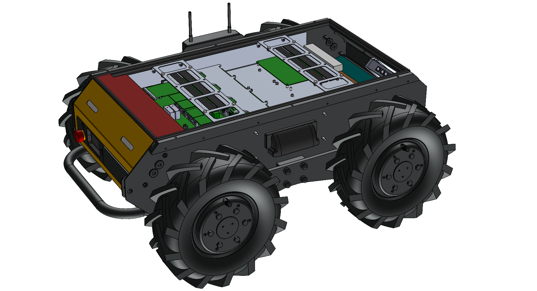
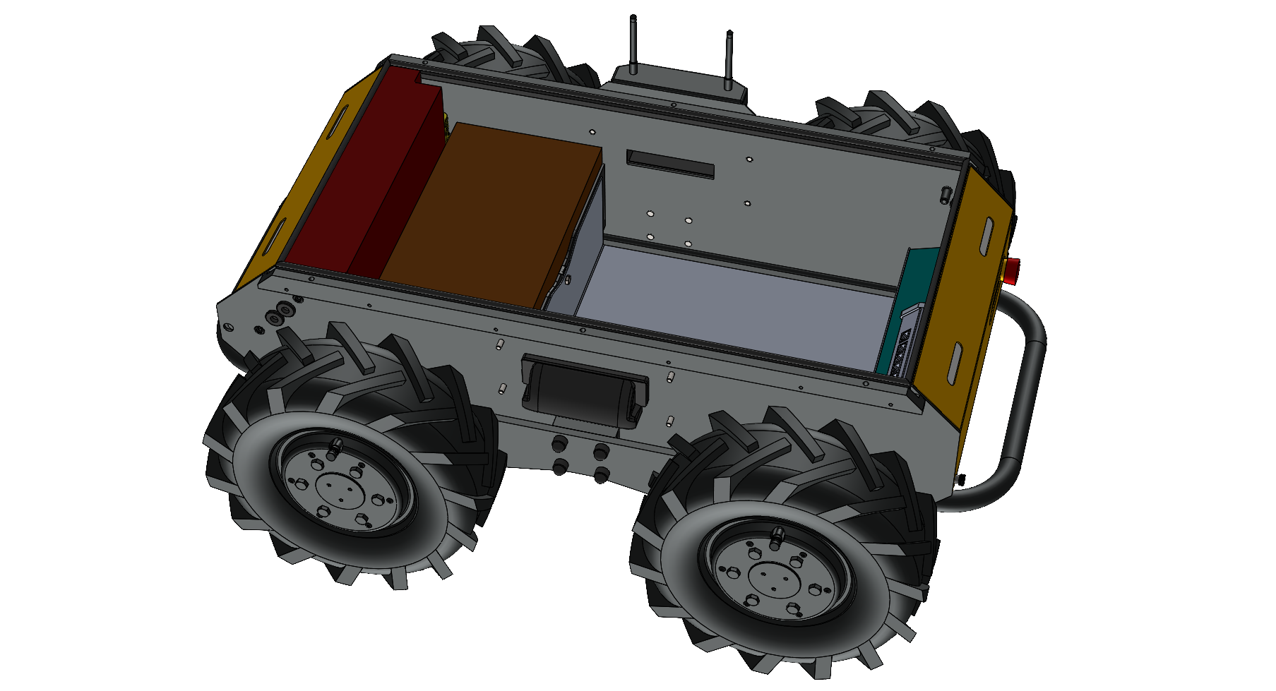
Internal Integrations
There are interfaces inside the Husky for your custom components. This Interface Control Drawing shows the available volume near the robot's batteries, noting that the size of this volume changes depending on what battery configuration your Husky has—(40 Ah, 80 Ah, or 120 Ah). The drawing also shows mounting provisions on the robot's Electronics Tray, for including these components:
- Husky's System Interface Assembly (circuit board with Husky's microcontroller, power supplies, and motor controllers)
- Primary computer
- IMU
- Add-on secondary computer or graphics card
- Add-on USB hub
Refer to the STEP model for more measurements of the Husky's interface areas.
This integration volume is available inside the base Husky A300, as well as Husky AMP and Husky Observer.
Electrical Integration
Refer to Cable Passthrough for details on how to pass cables through Husky's top plate for external payloads. |
Data Connections
These are our suggested methods for connecting sensors and actuators to Husky.
| Data Bus | Clearpath's suggestion for connecting devices to the Husky's computer: |
|---|---|
| USB | Direct connection to the robot's computer, or add a USB hub. |
| Ethernet | Connect to the robot's 2.5 Gbit/s Ethernet Switch, which is inside the chassis. |
| Serial RS-232, RS-422, RS-485 | Add a USB converter, such as a FTDI cable. Most computers have Serial ports, but these take more time to configure than a FTDI cable. |
| CAN | Add a USB converter, such as a PEAK System PCAN-USB. |
System Interface Connector Summary
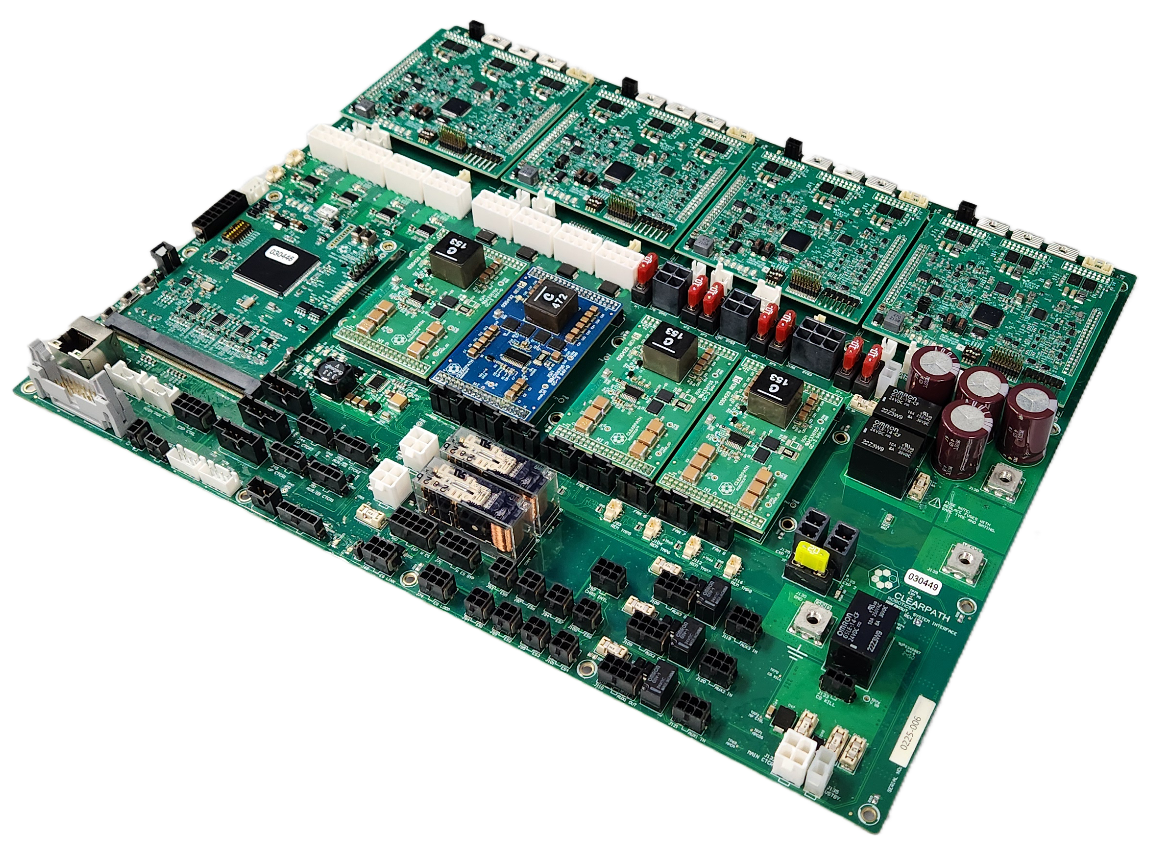
The System Interface Assembly is a circuit board that includes power supplies, lighting controllers, motor controllers, and the Husky's microcontroller. This circuit board has connectors for: power, fans, relays, GPIOs, auxiliary inputs, auxiliary outputs, and Emergency Stop devices.
| Purpose | Label on the circuit board | Connector on the circuit board | Mating connector | Mating connector's crimp | Crimping tool |
|---|---|---|---|---|---|
| User Power Connections | USER 1 - USER 8 | Molex 0039296088 | Molex 0039012080 | Molex 0039000140 (AWG 22-28) Or Molex 0039000073 (AWG 18-24) | Molex 0638191000 |
| Expansion Power | EXP 1 - EXP 2 | Molex 1720650202 | Molex 1700010102 | Molex 1720630311 (AWG 14-16) Or Molex 1720630312 (AWG 12) | Molex 2238631200 |
| AUX Inputs | AUX1 IN, AUX2 IN, AUX3 IN | TE 3-794682-6 | TE 794617-6 | TE 1-794606-1 (AWG 20-24) Or TE 1-794607-1 (AWG 26-30) | TE 91391-1 |
| AUX Outputs | AUX1 OUT, AUX2 OUT, AUX3 OUT | TE 3-794682-8 | TE 794617-8 | TE 1-794606-1 (AWG 20-24) Or TE 1-794607-1 (AWG 26-30) | TE 91391-1 |
| GPIO | GPIO | TE 4-794680-6 | TE 1-794617-6 | TE 1-794606-1 (AWG 20-24) Or TE 1-794607-1 (AWG 26-30) | TE 91391-1 |
| Fans | FAN 5 - FAN 8 | Molex 0705430003 | Molex 0050579404 | Molex 0016020103 (AWG 22-24) | Molex 0638118700 |
| Wireless Emergency Stop | W ES (Wireless E-Stop) | TE 4-794682-0 | TE 1-794617-0 | TE 1-794606-1 (AWG 20-24) Or TE 1-794607-1 (AWG 26-30) | TE 91391-1 |
| Emergency Stop Buttons | ES 3 - ES 8 (E-Stop) | TE 3-794682-4 | TE 794617-4 | TE 1-794606-1 (AWG 20-24) Or TE 1-794607-1 (AWG 26-30) | TE 91391-1 |
| Computer Power | SYS1 - SYS 2 | Molex 1720650204 | Molex 1700010104 | Molex 1720630311 (AWG 14-16) Or Molex 1720630312 (AWG 12) | Molex 2238631200 |
| Graphics Card Power | SYS3 | Molex 1720650206 | Molex 1700010106 | Molex 1720630311 (AWG 14-16) Or Molex 1720630312 (AWG 12) | Molex 2238631200 |
| Network Switch Power | SYS4 | Molex 0039281023 | Molex 0039012020 | Molex 0039000140 (AWG 22-28) Or Molex 0039000073 (AWG 18-24) | Molex 0638191000 |
Power Connections
User Power Connections
The System Interface circuit board has 8 User Power connectors, labelled USER 1 through USER 8.
User power is divided into 4 power rails and the power for each rail is shared across each of the 8 connectors. The maximum—(aggregate)—current available on each power rail is outlined in the table below. These circuits are protected with self resetting fuses. These circuits can also be toggled on and off through ROS.
| User Power Rail | Maximum (Aggregate) Current |
|---|---|
| 12 V Rail A | 5 A |
| 12 V Rail B | 5 A |
| 24 V | 5 A |
| VBAT (24 - 29 V, unregulated) | 5 A |
Do not exceed the specified maximum current limit of each power rail. Exceeding the maximum current may damage to your payload.
User Power Pinout
The pinout for each of the 8 connectors—(USER 1 through USER 8)—is illustrated below.
| USER connector pin | Function |
|---|---|
| 1 | 12 V (Rail B) |
| 2 | 12 V (Rail A) |
| 3 | 24 V |
| 4 | VBAT (24 - 29 V, unregulated) |
| 5 | GND |
| 6 | GND |
| 7 | GND |
| 8 | GND |
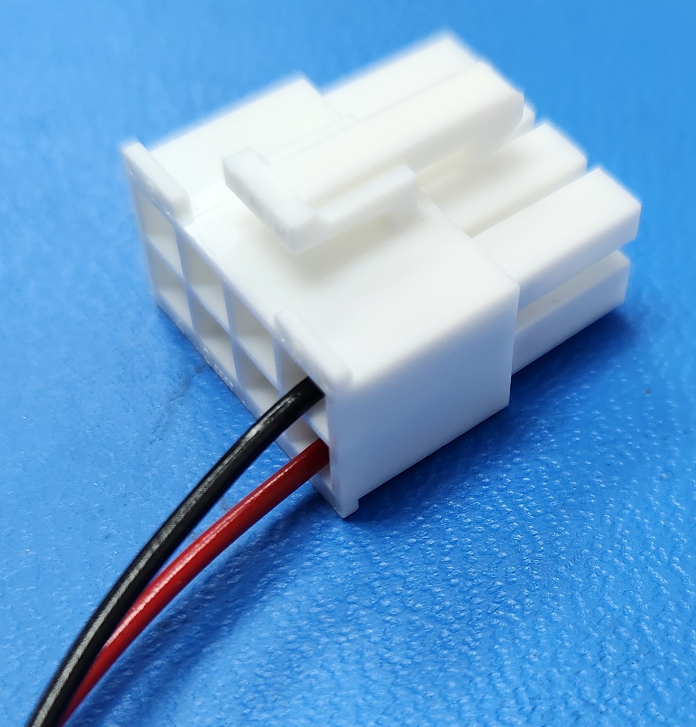
Making User Power Cables
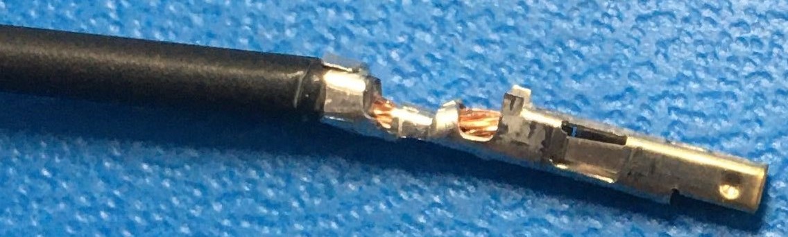
Connecting to user power requires the use of a Molex connector and compatible crimp terminals. To create these cables, follow the steps below.
- Expose about 5 mm of bare wire from the payload power leads and twist the exposed wire on both leads.
- Take 2 Molex terminals from the spare parts kit provided and insert the exposed wire and crimp the terminals, ensuring the wires are well secured inside the terminal, as shown below.
- Take 1 connector housing from the spare parts kit provided and insert the positive payload power lead—(red)—into position 1, 2, 3 or 4 of the connector until it locks into place. The positions numbers are visible on the back of the plastic housing.
- Insert the negative payload power lead (black) into position 5, 6, 7, or 8 of the connector until it locks into place.
For more technical information on the Molex power connectors, as well as their corresponding mating connectors, please visit the Digi-Key WM3703-ND Product Page.
Software Control of User Power Rails
User power can be enabled or disabled through ROS by publishing to /a300_#####/platform/mcu/cmd_user_power ROS topic.
-
To disable user power, run:
ros2 topic pub --once /a300_#####/platform/mcu/cmd_user_power std_msgs/msg/Bool '{data: false}' -
To enable user power, run:
ros2 topic pub --once /a300_#####/platform/mcu/cmd_user_power std_msgs/msg/Bool '{data: true}'
User Power is enabled by default shortly after the robot first powers up, regardless of its state when the robot was powered off.
Expansion Power (EXP 1 and EXP 2)
There are 2 Expansion Power connectors on the System Interface circuit board. The Expansion Power connectors can power small manipulators, DC-AC inverters, and DC-DC supplies.
These connectors supply VBAT voltage, with a combined current of up to 20 A. The connectors also include soft-start circuitry which limits inrush current to 25 A. This soft-start circuit reduces the chance of a high capacitance load causing the 20 A fuse to pop.
Use a Littelfuse 0297020.U as the replacement.
Expansion Power Pinout
The pinout for each of the 2 connectors—(EXP 1 and EXP 2)—is illustrated below.
| Expansion Power connector pin | Function |
|---|---|
| 1 | VBAT (24 - 29 V, unregulated) |
| 2 | GND |
Software Control of Expansion Power Rails
The Expansion Power connectors are connected to the same control system as the User Power. Refer to the Software Control of User Power Rails section for details.
High Power Expansion Kit (Large VBAT)
The optional High Power Expansion Kit can purchased at the time of your original Husky order—(Clearpath item 032001). We do not allow field installation of the kit.
We suggest you purchase a 80 Ah or 120 Ah Husky if you plan to operate on hills steeper than 5°, and have a payload of more than 50kg. 40 Ah battery configuration may not provide enough power in the worst case. Contact Support for more details.
Some high power payloads, such as manipulators, require more power than can be provided through the User Power connectors. The optional High Power Expansion Kit provides VBAT voltage at 40 A. It also includes 2 contactors for enabling and disabling power to the payload.
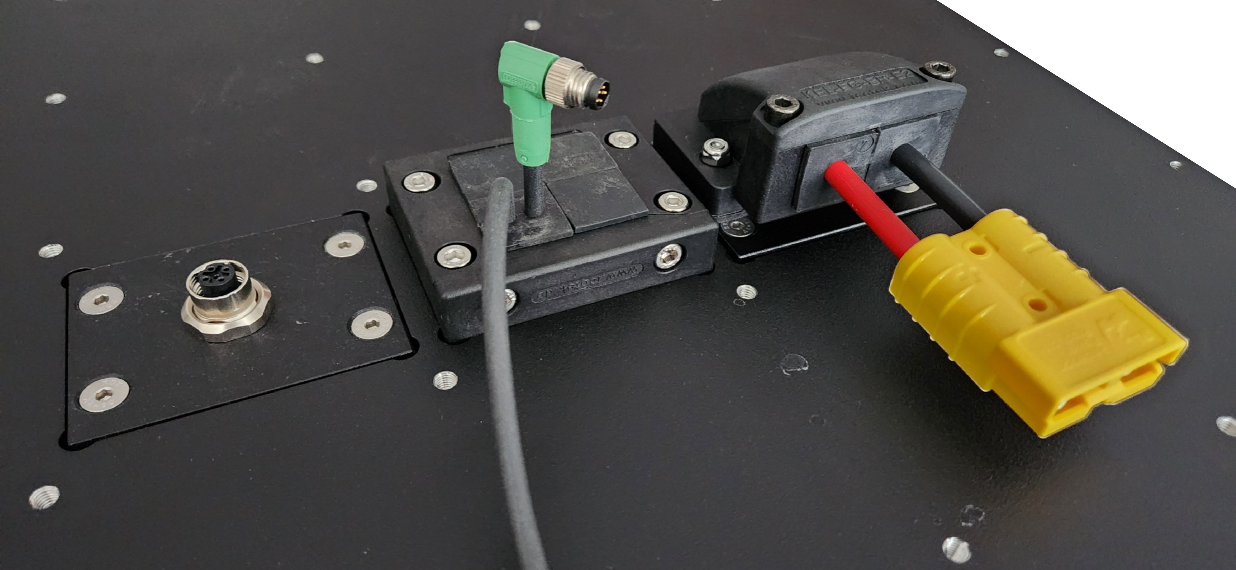
Making A Large VBAT Cable
We suggest using #10 AWG wire for this cable routing if it is completely inside the robot's chassis. We suggest using #8 AWG wire for this cable routing if it is outside the chassis, where someone could touch the cable. #8 AWG surface temperature is acceptable in an exposed cable for 40 A, per UL 1740.
The mating cable will connect to the yellow Anderson Power Products SB50 connector in left-rear of the robot's chassis, under the Top Plate.
Always observe local laws and electrical standards when building cables.
Consult the manufacturer's documentation for full details on proper crimping.
| Description | Vendor Part | CPR Part Number |
|---|---|---|
| Mating connector | Anderson 992G5-BK | 022554 |
| Crimps, #8 AWG | Anderson 5952-BK | 017281 |
| Crimps, #10 - #12 AWG | Anderson 5953-BK | 022562 |
| Crimping tool | Anderson 1309G4 | N/A |
Use a Littelfuse 142.5631.5402 as the replacement.
On/Off Control via Software
The High Power Expansion Kit output is controlled through software by publishing to the ROS topic /a300_#####/platform/mcu/cmd_high_power,
similar to Software Control of User Power Rails.
The High Power Expansion Kit output is always disabled when the system powers up. You must enable the output, via the ROS topic above, each time after the system powers up.
AUX Inputs
The System Interface circuit board has 3 auxiliary inputs—(AUX1 IN, AUX2 IN, AUX3 IN)—that allow external payloads to provide inputs to the robot. Each of these auxiliary inputs can be driven by one of the following:
- a 12 V input
- a 24 V input
- a push button or switch
The state of the input can be read from the ROS topic /a300_#####/platform/mcu/status/aux_inputs.
The AUX inputs are active low and are mapped to the ROS message bits as follows:
- AUX1 IN: bit 0
- AUX2 IN: bit 1
- AUX3 IN: bit 2
| AUX Input | Payload State | /a300_#####/platform/mcu/status/aux_inputs Value |
|---|---|---|
| AUX1 IN | 24 V on OR 12 V on OR button pressed 24 V off AND 12 V off AND button not pressed | bit 0 reads as '0' bit 0 reads as '1' |
| AUX2 IN | 24 V on OR 12 V on OR button pressed 24 V off AND 12 V off AND button not pressed | bit 1 reads as '0' bit 1 reads as '1' |
| AUX3 IN | 24 V on OR 12 V on OR button pressed 24 V off AND 12 V off AND button not pressed | bit 2 reads as '0' bit 2 reads as '1' |
AUX Input Pinout
The pinout for each of the connectors—(AUX1 IN, AUX2 IN, AUX3 IN)—is illustrated below.
| AUX IN Connector's Pin | Function |
|---|---|
| 1 | 24 V In |
| 2 | 12 V In |
| 3 | Button/Switch In, (3.3 V) |
| 4 | 24 V Return |
| 5 | 12 V Return |
| 6 | GND |
AUX Input Example #1
Consider the example where AUX2 IN has a 12 V supply connected to pins 2 and 5, with the remaining pins unconnected.
Monitor the input reading in ROS.
ros2 topic echo /a300_#####/platform/mcu/status/aux_inputs
| Action | /a300_#####/platform/mcu/status/aux_inputs value | Bit 2 Explanation | Bit 1 Explanation | Bit 0 Explanation |
|---|---|---|---|---|
| Begin with the 12 V supply turned off | 7 (8b00000111) | '1' since AUX3 IN is not connected | '1' since 12 V supply is off | '1' since AUX1 IN is not connected |
| Turn the 12 V power supply on | 5 (8b00000101) | '1' since AUX3 IN is not connected | '0' since 12 V supply is on | '1' since AUX1 IN is not connected |
| Turn the 12 V supply off | 7 (8b00000111) | '1' since AUX3 IN is not connected | '1' since 12 V supply is off | '1' since AUX1 IN is not connected |
AUX Input Example #2
Consider the example where AUX1 IN has a 24 V supply connected to pins 1 and 4, AUX2 IN has a 12 V supply connected to pins 2 and 5, and AUX3 IN has a push button connected to pin 3.
| Action | /a300_#####/platform/mcu/status/aux_inputs value | Bit 2 Explanation | Bit 1 Explanation | Bit 0 Explanation |
|---|---|---|---|---|
| Begin with 12 V supply turned off, the 24 V supply off, and the button not pressed | 7 (8b00000111) | '1' since button is not pressed | '1' since 12 V supply is off | '1' since 24 V supply is off |
| Turn the 24 V power supply on | 6 (8b00000110) | '1' since button is not pressed | '1' since 12 V supply is off | '0' since 24 V supply is on |
| Turn the 12 V supply on | 4 (8b00000100) | '1' since button is not pressed | '0' since 12 V supply is on | '0' 24 V supply is on |
| Press and hold the button | 0 (8b00000000) | '0' since button is pressed | '0' since 12 V supply is on | '0' 24 V supply is on |
AUX Outputs
The System Interface circuit board includes 3 outputs—(AUX1 OUT, AUX2 OUT, AUX3 OUT)—that can be controlled by publishing to the /a300_#####/platform/mcu/cmd_aux_outputs ROS topic.
To enable the AUX outputs, publish a single message with the appropriate bits set to 1 to turn the output on, and 0 to turn it off.
The state does not persist so new commands will need to keep the bit enabled as well.
The AUX outputs are mapped to the ROS message bits as follows:
- AUX1 OUT: bit 0
- AUX2 OUT: bit 1
- AUX3 OUT: bit 2
AUX Output Pinout
Each of the AUX outputs is an 8 position connector with pinout as outlined below. The output value is available in several modes:
- MOSFET outputs, (2X)
- Normally open relay
- Normally closed relay
| AUX OUT Connector Pin | Name | Function | Output when corresponding cmd_aux_outputs bit is '0' | Output when corresponding cmd_aux_outputs bit is '1' |
|---|---|---|---|---|
| 1 | AUX_24V | 24 V output, fused at 3 A | 24 V | 24 V |
| 2 | GND | GND | GND | GND |
| 3 | AUX_RELAY_NC | Normally closed relay pin | Connected to AUX_RELAY_COMMON | Floating |
| 4 | AUX_MOSFET2 | MOSFET #2 DRAIN | GND | Floating |
| 5 | GND | GND | GND | GND |
| 6 | AUX_RELAY_COMMON | Input that gets connected to AUX_RELAY_NC or AUX_RELAY_NO | Connected to AUX_RELAY_NC | Connected to AUX_RELAY_NO |
| 7 | AUX_RELAY_NO | Normally open relay pin | Floating | Connected to AUX_RELAY_COMMON |
| 8 | AUX_MOSFET1 | MOSFET #1 DRAIN | GND | Floating |
AUX Output Examples
-
To disable all AUX outputs:
rostopic pub /a300_#####/platform/mcu/cmd_aux_outputs std_msgs/UInt8 "data: 0" -
To enable all AUX outputs:
rostopic pub /a300_#####/platform/mcu/cmd_aux_outputs std_msgs/UInt8 "data: 7" -
To enable just the AUX3 output:
rostopic pub /a300_#####/platform/mcu/cmd_aux_outputs std_msgs/UInt8 "data: 4"
General Purpose Inputs and Outputs (GPIO)
The System Interface circuit board includes 4 general purpose inputs, and 4 general purpose outputs.
All GPIOs are at the 3.3 V logic level.
General purpose inputs are readable from the /a300_#####/platform/mcu/status/gp_inputs ROS topic.
Publishing to the /a300_#####/platform/mcu/cmd_gp_outputs ROS topic controls the general purpose outputs.
All the inputs and outputs are exposed through a single connector.
General Purpose Input Pinout
| GPIO connector pin | Function | gp_inputs value when driven at 0 V | gp_inputs value when driven at 3.3 V |
|---|---|---|---|
| 5 | GP In 1 | Bit 0 is '0' | Bit 0 is '1' |
| 6 | GP In 2 | Bit 1 is '0' | Bit 1 is '1' |
| 7 | GP In 3 | Bit 2 is '0' | Bit 2 is '1' |
| 8 | GP In 4 | Bit 3 is '0' | Bit 3 is '1' |
| 13 | GND | N/A | N/A |
| 14 | GND | N/A | N/A |
| 15 | GND | N/A | N/A |
| 16 | GND | N/A | N/A |
General Purpose Output Pinout
| GPIO connector pin | Function | Corresponding bit in cmd_gp_outputs | Output value when set to '0' | Output value when set to '1' |
|---|---|---|---|---|
| 1 | GP Out 1 | 0 | 0 V | 3.3 V |
| 2 | GP Out 2 | 1 | 0 V | 3.3 V |
| 3 | GP Out 3 | 2 | 0 V | 3.3 V |
| 4 | GP Out 4 | 3 | 0 V | 3.3 V |
| 9 | GND | N/A | GND | GND |
| 10 | GND | N/A | GND | GND |
| 11 | GND | N/A | GND | GND |
| 12 | GND | N/A | GND | GND |
Fan Expansion
The System Interface circuit board has support for 4 additional 12 V brushless 4-wire PWM fans. Ports FAN 1, FAN 2, FAN 3, and FAN 4 are already used by the base Husky A300. Ports FAN 5, FAN 6, FAN 7, and FAN 8 are available for your fan expansions.
The pinout for each fan is:
| Pin | Function |
|---|---|
| 1 | 12 V |
| 2 | GND |
| 3 | Tachometer (output from fan) |
| 4 | PWM (input to fan, 3.3 V) |
The speed of each fan can be controlled by publishing to the /a300_#####/platform/mcu/cmd_fans ROS topic.
The speed of each fan can be monitored by reading the /a300_#####/platform/mcu/status/fans ROS topic.
In both cases, the fan value is in the range from 0 (not spinning), to 255 (max speed).
Fans require spool up time on startup. Setting a fan to a very low value may result in the fan not rotating. You should experiment to find minimum PWM value that causes your fan to spin.
Wireless Emergency Stop
A wireless dual-channel emergency stop can be added to Husky. This allows you to invoke an emergency stop remotely—(either through a button press or when the remote unit is out of range). This is in addition to the Husky's built-in Emergency Stop Buttons. Refer to the User Manual for details on how the Wireless Emergency Stop can be bypassed in certain debugging scenarios.
The Wireless Emergency Stop can be connected to Husky on the System Interface circuit board at the W ES connector, based on the pinout below.
| W ES Pin | Function / Value |
|---|---|
| 1 | 24 V, (fused at 3 A) |
| 2 | CAN High: combined with CAN Low, connected to the CAN2 pins on the MCU; see additional notes below |
| 3 | Reset In: Pull to GND for at least 100 ms to restart the robot after all emergency stops have been cleared; equivalent to pressing the Restart Button on Husky |
| 4 | Channel 1 Out, (24 V): normally connected to Channel 1 In; disconnect to trigger an emergency stop |
| 5 | Channel 1 In |
| 6 | GND |
| 7 | CAN Low |
| 8 | GND |
| 9 | Channel 2 Out, (24 V): normally connected to Channel 2 In; disconnect to trigger an emergency stop |
| 10 | Channel 2 In |
Receiver Installation
In addition to the electrical integration noted above, the wireless receiver will normally require mechanical mounting inside the Husky, along with external mounting of an antenna. Refer to Wireless Stop receivers and Cable Passthrough for additional details.
CANbus Connection
Husky has up to 3 standard CAN networks:
| Network name | Data Rate | Purpose | Devices |
|---|---|---|---|
vcan0 | 1000 kBit/s | Motor Control | Primary Computer, MCU, 4 Motor Controllers |
vcan1 | 250 kBit/s | Batteries | Primary Computer, MCU, Batteries (up to 6 batteries), Wireless Emergency Stop |
usbcan0 | 250 kBit/s | Optional Wireless Charger | Primary Computer, Wireless Charger |
We suggest you add custom CAN devices to a new network, using a USB-CAN adapter such as a PEAK System PCAN-USB. You would need to name the new network something different than the 3 networks listed above. We configure these networks using SocketCAN.
It is possible to add new devices to the Husky's existing networks, but this requires significant testing time.
Additional Emergency Stop Devices
The base Husky A300 includes 2 Emergency Stop Buttons, which are connected to the System Interface circuit board. The System Interface circuit board also includes connector breakouts for 6 more Emergency Stop devices, labelled ES3 through ES8. The standard Husky A300 has a bypass jumper inserted into each of these unused Emergency Stop breakouts.
You can use these Emergency Stop breakouts to add more Emergency Stop devices, such as:
- Emergency Stop buttons
- Safety lidar
- Tape switches
- Limit switches
- Relays or similar PLC components
- Manipulator control cabinets
| ES Pin | Function / Value |
|---|---|
| 1 | Channel 1 Out, (24 V): normally connected to Channel 1 In; disconnect to trigger an emergency stop |
| 2 | Channel 1 In |
| 3 | Channel 2 Out (24 V): normally connected to Channel 2 In; disconnect to trigger an emergency stop |
| 4 | Channel 2 In |
System Power
These 4 connectors collectively provide up to 400 W of power at 12 V for powering computers and network equipment.
SYS1 And SYS2 Pinouts For Computers
| Pin | Function / Value |
|---|---|
| 1 | 12 V |
| 2 | 12 V |
| 3 | GND |
| 4 | GND |
SYS1 is always being used by the robot's Primary Computer.
SYS3 Pinout For A Graphics Card
| Pin | Function / Value |
|---|---|
| 1 | 12 V |
| 2 | 12 V |
| 3 | 12 V |
| 4 | GND |
| 5 | GND |
| 6 | GND |
SYS4 System Power For A Network Switch
This provides 60 W of power at 12 V.
| Pin | Function / Value |
|---|---|
| 1 | 12 V |
| 2 | GND |
Software Integration
ROS has a large ecosystem of sensor drivers, some of which include pre-made URDF descriptions and even simulation configurations. Refer to Sensors supported by ROS.
For the best experience, consider purchasing supported accessories from Clearpath Robotics for your robot, which will include simulation, visualization, and driver support.
Refer to the following for more details:
Support
Clearpath is committed to your success. Please get in touch with us and we will do our best to get you rolling again quickly: <support@clearpathrobotics.com>.
To get in touch with a salesperson regarding Clearpath Robotics products, please email <research-sales@clearpathrobotics.com>.
If you have an issue that is specifically about ROS and is something which may be of interest to the broader community, consider asking it on Robotics Stack Exchange. If you do not get a satisfactory response, please ping us and include a link to your question as posted there. If appropriate, we will answer on Robotics Stack Exchange for the benefit of the community.