TF Validation
Sensor transform (TF) validation should only be required if the performance is noticeably poor, such as when the UGV drifts off of the planned path or oscillations occur around the path).
The coordinate transformation of the two GPS antennas, the IMU, the 2D and 3D Lidars to the base_link of the UGV should have already been set prior to receiving the UGV. However, ensure that they are set correctly.
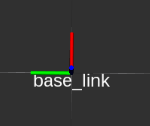
The ROS coordinate frame base_link, shown in the figure below, is located at the center of the bottom plate of the UGV. The environment variables below should be taken with respect to this coordinate frame. The X axis is in red (and pointing towards the front of the UGV), Y in green (pointing towards the left of the UGV) and Z in blue (pointing towards the sky).
You can check the current value of the environment variables by running the following on the robot (host) computer (and setting <variable_name> to the names listed in the table below).
printenv | grep <variable_name>
The environment variables for the position and orientation of each sensor are provided in the table below.
OutdoorNav sensor position and orientation environment variables
| Environment Variable | Function |
|---|---|
| POSITION_GPS_XYZ | [X,Y,Z] position, in meters, of the position GNSS antenna with respect to the base_link coordinate frame. |
| POSITION_GPS_RPY | [Roll,Pitch,Yaw], in radians, of the position GNSS antenna with respect to the base_link coordinate frame. |
| HEADING_GPS_XYZ | [X,Y,Z] position, in meters, of the heading GNSS antenna with respect to the base_link coordinate frame. |
| HEADING_GPS_RPY | [Roll,Pitch,Yaw], in radians, of the heading GNSS antenna with respect to the base_link coordinate frame. |
| MICROSTRAIN_XYZ | [X,Y,Z] position, in meters, of the IMU with respect to the base_link coordinate frame. |
| MICROSTRAIN_RPY | [Roll,Pitch,Yaw], in radians, of the IMU with respect to the base_link coordinate frame. |
| VLP_XYZ | [X,Y,Z] position, in meters, of the 3D Lidar with respect to the base_link coordinate frame. |
| VLP_RPY | [Roll,Pitch,Yaw], in radians, of the 3D Lidar with respect to the base_link coordinate frame. |
| LMS1XX_XYZ | [X,Y,Z] position, in meters, of the 2D Lidar with respect to the base_link coordinate frame. |
| LMS1XX_RPY | [Roll,Pitch,Yaw], in radians, of the 2D Lidar with respect to the base_link coordinate frame. |
| HOKUYO_XYZ | [X,Y,Z] position, in meters, of the 2D Lidar with respect to the base_link coordinate frame. |
| HOKUYO_RPY | [Roll,Pitch,Yaw], in radians, of the 2D Lidar with respect to the base_link coordinate frame. |
| D435_XYZ | [X,Y,Z] position, in meters, of the 2D Lidar with respect to the base_link coordinate frame. |
| D435_RPY | [Roll,Pitch,Yaw], in radians, of the 2D Lidar with respect to the base_link coordinate frame. |
There may also be 2 of each of these detection sensors. The corresponding environment
variable is prefixed with REAR_.
When the printed Y axis on the IMU is pointing towards the front of the robot (i.e., aligned to X axis of base_link), MICROSTRAIN_RPY = [0, 0, 0].
If you decide to move any of these sensors, you must modify these
variables accordingly in the /opt/onav/outdoornav_host_setup.sh file (on the host).