When tuning controllers, it is advised to always only modify one single parameter prior to each test. This allows the user to analyze the effect of this single parameter on the controller performance.
Tuning Flowchart
When attempting to tune the navigation controller, it is recommended to follow the following flowchart. Begin with setting up Initial Parameters for your UGV.
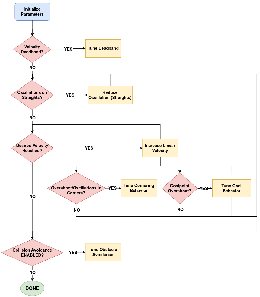
Condition Blocks: The condition blocks can be seen in the flowchart as RED decision blocks and either contain tests needed to be run or features of the software that are enabled/disabled.
Tuning Blocks: The tuning blocks can be seen in the flowchart as YELLOW blocks where it is expected that the user modifies a parameter prior to re-testing the controller.
Conditions Blocks
Velocity Deadband Tests
The "Velocity Deadband?" condition block asks the user to verify if there is a velocity deadband that the UGV motors must overcome in order to move the UGV. (ie. what is the minimum velocity that the UGV is required to receive, in order for it to move).
To verify this, the user should set up two missions:
- A two Waypoint mission where the first Waypoint is located on the robot, and second Waypoint about 10-20 meters directly in front of the UGV. This will verify the requried linear motion of the UGV.
- A two Waypoint mission where the first Waypoint is located on the robot, and second Waypoint about 10-20 meters directly behind the UGV. The first part of the navigation to this point (ie. the rotation to face the Waypoint) will verify the required angular motion of the UGV.
If the above tests demonstrate that the UGV is stuck in a velocity deadband and is not moving, then proceed to Tune Deadband.
If the above tests demonstrate that the UGV is NOT stuck in a velocity deadband (ie. it can smoothly start navigating the mission), proceed to the following condition block: Oscillation Tests.
Oscillation Tests (Straights)
The "Oscillations on Straights?" conditions block asks if there are any oscillations present during normal navigation along a straight path.
Tests
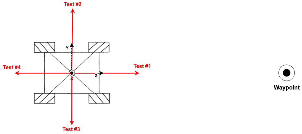
To verify the amount of oscilations around the reference path, the user should set up four missions, each of which should pass (or fall within the users requirements) prior to moving on from this section of the tuning. The start and end points of each of the tests should be identical and the start position (XY) should be noted/marked on the testing area. The first Waypoint should be placed on the robots current location and the second Waypoint should be placed 20-30m away from the start position. The four UGV orientations for each test are as follows:
- Align the UGV with a 0° offset from the Waypoint.
- Align the UGV with a 90° offset from the Waypoint.
- Align the UGV with a -90° offset from the Waypoint.
- Align the UGV with a 180° offset from the Waypoint.
See the image below to determine the placement of the UGV. The red arrow indicates the orientation of the UGV with respect to the Waypoint.
It is not necessary to run all of the offset tests after every parameter change. It is enough to progress systematically through the tests as they succeed. That is, if there are no oscillations during a 0° offset test, proceed to run the 45° test and so on and so forth. If the 0° offset test fails, then there is no need to run the other three tests before updating a parameter. The condition has been satisfied when all of the test results in minimal to no oscillations (or as is deemed acceptable).
Causes
Oscillations during navigation along straight paths can be caused by one or several of the following reasons. They are listed here in order of likelihood of occurence:
| Cause | Description | |
|---|---|---|
| 1 | Untuned MPC parameters | The default MPC controller parameters have been tuned for CPR UGVs, and may not be the same for third-party OEM UGVs. |
| 2 | Controller delay | There may be delay present in your UGV between the time the navigation computes a command velocity and when the velocity is actually executed. This could appear as mechanical delay in your motors or even mechanical delay in the rotational components of UGVs control mechanisms . It is rarely noticed when electrical motors are used. The effect of controller delay is most commonly noticed when when entering a straight from a curve or after a pure rotation. |
| 3 | Deformable Tires | If your tires are deformable, then after coming out of a pure rotation, while the UGV may be facing the required direction of travel, a purely linear command velocity would cause the UGV to veer off to the left/right. This in turn would cause the controller to correct itself, and place it into an oscillatory motion. |
| 4 | Uneven weight distribution | If your UGV is carrying more weight on one side it may bias the UGVs motion when being command straight and veer the UGV off to one side. The controller would then consistently try to correct this bias by pulling it back towards the reference path, thus causing oscillations. |
To determine if causes 3 and 4 may apply to you, it is a good idea to run the following test:
- send the following command to rotate your UGV for one full rotation,
rostopic pub /cmd_vel geometry_msgs/Twist "linear:
  x: 0.0
  y: 0.0
  z: 0.0
angular:
  x: 0.0
  y: 0.0
  z: 0.3" -r 10
- stop the rotation by stopping the command.
- send the following command to move the UGV purely forward,
rostopic pub /cmd_vel geometry_msgs/Twist "linear:
  x: 0.5
  y: 0.0
  z: 0.0
angular:
  x: 0.0
  y: 0.0
  z: 0.0" -r 10
- Analyse the motion and then stop the linear motion. If the UGV drifts left/right during step 3, then your UGV is likely to suffer from the effect of uneven weight distribution or deformable tires. (If not, there may be bigger issues). Further investigation/discussion with Clearpath would be required.
If the above tests demonstrate that the UGV is oscillating around the reference path, then proceed to Reduce Oscillations.
If the above tests demonstrate that the UGV is NOT oscillating or within an acceptable range of oscillation, proceed to onto the following condition block: Velocity Increase.
Linear Velocity Condition/Test
The "Increase Linear Velocity?" condition block asks if the user wants to increase the linear velocity that the UGV will travel along long straight paths. This does not mean that it will always drive at this velocity, but it is the velocity that it will accelerate to on straights, when starting a mission and/or when coming out of a curve.
To test this we want to create a mission that sends the UGV to a Waypoint directly in front of the UGVs current position. This requires two Waypoints: the first one located at the robots current position and the second Waypoint at least 20 meters away from the start position and will depend on the linear velocity you wish to acheive.
If during the above test, the velocity does not reach the desired velocity, proceed to Increase Linear Velocity and repeat the above test until the desired has been achieved.
If the above test results in the UGVs maximum velocity reaching the desired velocity, then proceed to checking the two subconditions: Goal Behavior and Cornering Behavior.
Only advance to the following condition block: Collision Avoidance if the UGVs maximum velocity has reached the desired velocity and all subconditions are also satisfied. Ie. you have tuned the corner and goal behavior to within your allowable limits.
Goal State Tests
The "Goalpoint Overshoot?" condition block asks the user to check if, at the end of a mission, the UGV overshoots the goalpoint. This condition should always be checked every time the velocity is increased. A similar test can be used as in the Velocity Increase section.
If the test results in the UGV overshooting the goal point, then proceed to Tune Goal Behavior.
If the test results in a smooth deceleration to the goal point, with the UGV completing its mission within the required tolerance, and NO overshoot, then proceed to re-verifying that your changes have not caused any oscillations by returning to the Oscillation Tests.
Only advance to the following condition block: Collision Avoidance if the UGVs maximum velocity has reached the desired velocity and all subconditions also are also satisfied. Ie. you have tuned the corner and goal behavior to within your allowable limits.
Corner State Tests
The "Overshoot/Oscillations in Corners?" condition block asks the user to check if the UGV overshoots the entry to corners, and/or if the UGV oscillates during the cornering. This condition should always be checked every time the velocity is increased.
A test should be designed so that the UGV will navigate a curve/corner. This type of mission can be set up regardless of whether or not you have set a specified turn radius for the path planner.
The Waypoints for the test mission should be placed such that there is sufficient change in orientation of the reference path that the controller will switch into its CORNER state. An example mission is provided below which demonstrates said Waypoint placement (although an extreme case with lots of Waypoints for vehicle with a large turn radius).
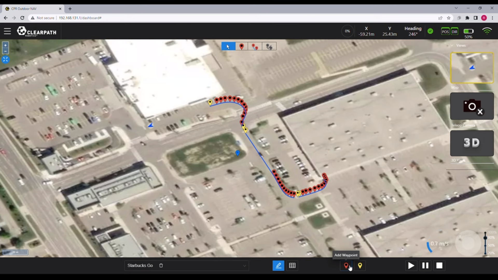
For the current case of differential drive UGVs who are able to turn on the spot, simpler test missions can be used that change the heading of the UGV more than 45°, at each Waypoint.
If the test results in the UGV overshooting the entrance to the corner/curve, then proceed to the first issue listed in Tune Corner State.
If the test results in the UGV oscillating during the corner/curve, then proceed to the second issue listed in Tune Corner State.
If the test results in the UGV navigating smoothly through all curves/corners, with no minimal oscillations and no overshoot, then proceed to re-verifying that your changes have not caused any oscillations during straights (Oscillation Tests).
Only advance to the following condition block: Collision Avoidance if the UGVs maximum velocity has reached the desired velocity and all subconditions are also satisfied. Ie. you have tuned the corner and goal behavior to within your allowable limits.
Collision Avoidance Condition
The final condition block asks the user if collision avoidance is enabled or disabled on the UGV.
If collision avoidance is DISABLED, then you have completed tuning your UGV. Congratulations!
When collision avoidance is ENABLED, it is recommended to begin with a straight line test as in Velocity Increase but with an obstacle placed roughly in the center of the predicted path (ie. at the midpoint between the start and goal locations). This obstacle should be at least 30 cm tall and at least 10 cm wide. The user should be ready to emergency stop the UGV if they notice it approaching the obstacle too fast or too closely.
If the test results in any unexpected behaviour, such as:
-
not stopping in front of the obstacle,
-
not navigating after stopping in front of the obstacle,
-
jittery motion navigating around the obstacle,
then proceed to the respective issue listed in Tune Collision Avoidance Behavior.
Tuning Blocks
Initialize Parameters
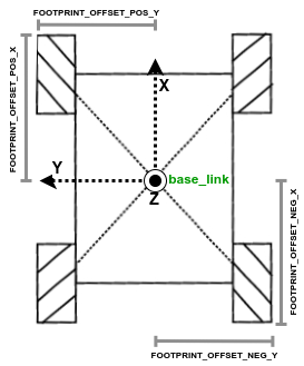
- Update the footprint offsets of the UGV in the
/opt/onav/<onav_version>/config/autonomy.envfile, where onav_version is the version of OutdoorNav that you are currently running.
This above file path is only valid for versions after and including version 0.11.0.
| Environment Variable | Description | Sign |
|---|---|---|
| FOOTPRINT_OFFSET_POS_X | Distance from base_link to the furthest edge of any part/sensor at the front of the UGV. | + |
| FOOTPRINT_OFFSET_NEG_X | Distance from base_link to the furthest edge of any part/sensor at the left of the UGV. | - |
| FOOTPRINT_OFFSET_POS_Y | Distance from base_link to the furthest edge of any part/sensor at the rear of the UGV. | + |
| FOOTPRINT_OFFSET_NEG_Y | Distance from base_link to the furthest edge of any part/sensor at the right of the UGV. | - |
-
Update the
vehicle_lengthparameter to be the longitudinal length (ie. along the x-axis) of your UGV. This is not the sum of the above footprint x-axis magnitudes, but only the length of the UGV body. -
Update the following parameters with your UGV specific maximums and minimums:
-
Update the
stiction_compensator_fwdandstiction_compensator_yawto be equivalent to the minimum linear and angular velocities that the UGV requires it to move (eg.stiction_compensator_fwdwould be equal tomin_fwd_velocity).
Tune Velocity Deadband
To tune the velocity deadband, the user should at least start off by knowing the minimum linear and angular velocities that the UGV motors can generate.
If not already set from the Initial Parameters section, you should set
the min_fwd_velocity to the minimum
forward linear velocity that the UGV can handle.
For each iteration of the linear deadband tuning, increment the following parameters by 0.05 m/s , until smooth linear motion is acheived from standstill:
For each iteration of the angular deadband tuning, increment the following parameters by 0.02 rad/s , until smooth angular motion is acheived from standstill:
Reducing Oscillation (Straights)
To tune the UGV behavior on straights when dealing with the simple cause of untuned MPC controller parameters, we list the following parameters along with likely ranges and their initial default values. The are listed in order of which parameter will have the most effect of improving the performance of the current tuning block.
| Parameter | Likely Range* | Default |
|---|---|---|
yaw_weight | 90 - 120 | 18.0 |
y_weight | 12 - 18 | 14.0 |
endpoint_multiplier | 10 - 20 | 10 |
max_lookahead | 2.5 - 3.5 | 2.5 |
x_weight | 14 - 16 | 14.0 |
lookahead_factor | 1.4 - 1.6 | 1.45 |
mpc_opt_maxiteration* | 10 - 15 | 13 |
discretization_steps* | 6 - 10 | 8 |
* These parameters should be changed with caution.
When you are experiencing oscillations due to cause #2 (controller delay) try the modifying the following parameters:
| Parameter | Likely Range* | Default |
|---|---|---|
enable_delay_compensation | true | false |
controller_delay | depends on your delay in your system. (usually between 300 - 1000 will provide changes to the performance) | NA |
No available solutions yet to resolve oscillations due to causes #3 and #4. Please contact Clearpath customer support at support@clearpathrobotics.com to discuss any related issue.
Increase Linear Velocity
** The following instructions are only relevant if you are planning on increasing the velocity of the UGV above 2.0 m/s. **
To increase the UGVs maximum velocity, the following parameters should be modified.
First, the mpc_horizon parameter
should be set to: 1.0
The following parameters should then be modified to the desired velocity (). Ie. if m/s, then you should modify both parameters to be 4.0.
| Parameter | Value |
|---|---|
max_fwd_velocity | |
max_lookahead |
Finally, if you are increasing the velocity to a value greater than or equal to 4.0 m/s or if you
are seeing that the velocity is being limited even after changing the above parameters,
it is possible to try and increase the size (width and height) of the local costmap in file:
/opt/onav/<onav_version>/app/autonomy/params/platform/navigation/costmap_local.yaml,
where onav_version is the currently running version of OutdoorNav. The limit in the velocity
is due to the fact that the lookahead distance at higher speeds ends up exceeding the size of
the local costmap. By increasing it, we allow the controller to lookahead further and allow for
that velocity increase.
Tune Goal State
A few different issues may have occurred that led you to tuning the goal behavior. We list a few of them and the possible parameters that can be modified to improve the performance in and around the goal point.
- Overshooting the goal point can be caused by a few factors:
- Not decelerating fast enough or soon enough as the UGV approaches the goal.
To tune for this issue, some parameters are listed in order in which they will have the most effect of improving the performance of the current tuning block:
| Parameter | Default |
|---|---|
goal_horizon_threshold | 2.0 |
goal_slowdown_multiplier | 1.5 |
goal_horizon_threshold | 0.8 |
endpoint_multiplier_goal | 20 |
x_weight_goal | 14.0 |
fwd_v_weight_goal | 0.01 |
fwd_a_weight_goal | 8.0 |
- The autonomy core not considering the goal complete because it has too high of a velocity as it starts entering the goal tolerance.
To to tune for this issue, modify the following parameter:
| Parameter | Value | Default |
|---|---|---|
max_speed_at_goal | depends on the deceleration of your UGV | 0.8 |
- Oscillations (or jittery behavior) around the goal point are typically caused by the the tolerance at the goal point being set too small. If they are too small and the UGV is unable to localize itself within the required position and yaw tolerances, then it will jitter and rotate to attempt to be a precise as you are expecting it to be. To resolve this, it is advised to slightly increase the goal tolerance parameters:
| Parameter | Default |
|---|---|
goal_tolerance_xy_rtk | 0.1 |
goal_tolerance_yaw_rtk | 0.25 |
goal_tolerance_xy_nortk | 0.3 |
goal_tolerance_yaw_nortk | 0.5 |
If your UGV has RTK corrections, then it is only required to modify goal_tolerance_xy_rtk
and goal_tolerance_yaw_rtk. Otherwise,
only modify goal_tolerance_xy_nortk
and goal_tolerance_yaw_nortk.
A complete list of parameters that relate to the GOAL state can be found here, however, the above set of parameters is likely to satisfy the users requirements.
Tune Cornering State
A few different issues may have occured that led you to tuning the cornering behavior. We list a few of them and the possible parameters that can be modified to improve the performance approaching as well as in the corner.
- Overshooting the corner only to enter the turn late
This issue occurs most often, when the controller is unable to slow the UGV down early and/or fast enough, prior to entering the corner. A reduction in velocity earlier in the approach to the corner will improve the cornering performance. Below some parameters are listed that will allow the user to improve the behavior entering corners:
| Parameter | Default |
|---|---|
corner_segment_slowdown | false |
corner_lookahead | 5.0 |
corner_detection_threshold | 0.15 |
corner_slowdown_multiplier | 1.5 |
- Oscillations during the corner
To reduce the oscillations in the corners, some parameters are listed in order in which they will have the most effect of improving the performance:
| Parameter | Default |
|---|---|
endpoint_multiplier_corner | 20.0 |
curvature_slowdown | 0.15 |
controller_delay | 0 |
y_weight | 14.0 |
x_weight | 14.0 |
The complete list of parameters that relate to the CORNER state can be found here, however, the above set of parameters is likely to satisfy the users requirements.
Tune Collision Avoidance
A few different issues may have occured that led you to tuning the collision avoidance. We list a few of them and the possible parameters that can be modified to improve the performance approaching as well as navigating around detected obstacles.
- UGV not stopping in front of the obstacle
This issue would either occur if the collision avoidance has been disabled, or if the detection sensors are not populating the costmap with the obstacle(s). To enable/disable collision avoidance:
| Parameter | Default |
|---|---|
ENABLE_COLLISION_AVOIDANCE | true |
For the case where the obstacle that you are using is not being detected by the detection sensors, make sure that it is neither too short nor too thin. Use RViz to check that the local costmap is being populated with the obstacle.
- UGV not navigating after stopping in front of an obstacle
This issue is either due to the robot unable to replan around the obstacle, in which case the following parameters may help:
| Parameter | Default |
|---|---|
inflation radius | 1.0 |
cost_scaling_factor | 0.5 |
max_decel | 0.5 |
max_accel | 0.5 |
or that the obstacle has gotten inside of the safety footprints causing the navigation to place the UGV in a collision state:
Consult the Footprint Tuning instructions to increase the safety footprint sets. The user can also try increasing the stop distance from the UGV to an obstacle as it decelerates to a stop.
| Parameter | Default |
|---|---|
enable_stop_distance radius | false |
obstacle_stop_distance | 3.0 |
- UGV has jittery motion navigating around the obstacle,
This issue is typically a problem when the safety footprints collide with the obstacle as it is trying to navigate the replanned path around the obstacle:
Consult the Footprint Tuning instructions to modify the safety footprint sets.
The user can also try increasing the stop distance of the UGV to an obstacle.
| Parameter | Default |
|---|---|
enable_stop_distance radius | false |
obstacle_stop_distance | 3.0 |
- UGV suddenly reducing its velocity as it accelerates up to maximum
This issue is due to the safety footprints exceeding the length of the local costmap. Since the safety footprints increase in length as the velocity increases, the user must also increase the size of the local costmap. This allows the safety footprints to extend to their entire length without triggering a "false" obstacle detection due to the footprint exceeding the local costmap size. Increase the costmap using these parameters:
| Parameter | Default |
|---|---|
local_costmap/width | |
local_costmap/height |
where l_{max_footprint} is the length of the largest safety footprint.