Warthog Maintenance
Battery and Charging
Overview
Warthog contains a 48 V lead-acid battery pack, consisting of four 12 V lead-acid batteries, or a LiFEPO4 battery pack, consisting of four 118 Ah 12.8 V batteries connected in a 4S1P configuration with a single Battery Management System (BMS) control unit. Battery configuration may vary with each unit. In order to maximize performance, it's important to ensure that the battery level across each set of lead-acid or LiFEPO4 batteries is within 0.1-0.2 V. If the batteries exceed this tolerance, it's advised to charge them to within tolerance before wiring these packs in parallel. The overall battery life will vary depending upon the usage of the unit. The typical lifetime of a lead-acid battery pack is approximately 250-300 charge/discharge cycles, depending on the depth of discharge.
Battery Management System
If your Warthog is equipped with a lead-acid battery pack, you can ignore this section on the Battery Management System.
Your charger must be disconnected completely from the Warthog when not charging the unit. Leaving the cable plugged into the Warthog enables the BMS system to be powered on fully even when the robot is off, which will cause the batteries to be drained to an over-discharged state.
If your Warthog is equipped with a LiFEPO4 battery pack, it is also equipped with a single Battery Management System (BMS) control unit. The main function of the BMS is to:
- Protect the individual modules from being overcharged or excessively discharged.
- Protect the modules from operating outside of their acceptable temperature range.
- Provide status information to higher level systems via a CAN interface.
- Provide independent system management without a higher level control system.
- Provide status, warning and error messages from each of the modules connected to the battery power system.
- Control the charging operation.
- Perform module to module balancing of the system, the battery module will control cell balancing within itself.
There is a main power contactor which is controlled by the BMS unit and is placed in such a way that it controls all power to the system. Upon turning on the main disconnect switch:
The BMS powers up first and begins communicating with all of the battery modules in the system.
- If they are all present and have no errors the BMS will close the main contactor and allow the Warthog to power up as normal,
this process can take a few seconds before the main contactor closes.
- If all the modules are not present, the system State of Charge (SOC) is too low, or there are errors being reported by any of the modules in the system, the contactor will not close, and the system will not power up.
- Similarly, if a user is in discharge mode (the Warthog is in use) and any errors are detected, or if the SOC falls to a cut off point,
the contactor will open and remove power from the system to protect the modules.
- It is not good practice to run the state-of-charge (SOC) to 0%. This will decrease the life of the battery module. In general, keeping the SOC to a minimum of 30-50% can increase the lifetime of the batteries.
- As a note, the system SOC is identical to the module with the lowest SOC in the system, so if three modules are at 45% SOC, and one module is at 25%, then the SOC of the system is 25%, and the BMS will act accordingly cutting off power to protect the module with the lowest SOC. Cell balancing and proper charging techniques are important to maintaining good battery health.
- The Warthog can be charged when the unit is powered and running, and can also be charged when the unit is not powered (main disconnect switch is open).
- The charger has been configured and wired in a way that the BMS is actually controlling the charger and can turn it off, and on, depending on the status of the charging cycle.
- Even though the unit can be charged while running, this process does not allow for proper cell balancing to occur. It will allow for bulk charge to occur to regain most of the charge in the system, however, repeatedly charging in this manner will allow each module to become out of balance with the other modules. If this process if followed long enough the SOC values for each module can vary by a substantial amount. The larger the variation, the longer it will take to fully balance the system. Therefore it is recommended (depending on use) that at least once every two to three weeks that the system be completely charged while the main disconnect switch is in the off position. Doing so will allow the BMS to go through an equalization phase where the charger is being turned on and off by the BMS to balance the voltages across each cell layer, in each module across the system. This is a very important step in maintain battery health, and getting the maximum lifetime out of the battery system.
- Refer to BMS ROS Topics to view the necessary topics through the ROS API.
- To allow for this level of control there are three contactors in the system:
- The main contactor for discharge of the system.
- The charge contactor to connect to the output of the charger.
- The charge control relay to turn the charger outputs on and off and control the cell balancing or equalization phase of the charge cycle.
BMS ROS Topics
If your Warthog is equipped with a lead-acid battery pack, you can ignore this section on the BMS ROS Topics.
The table below shows topics that will be very useful in monitoring battery health, as outlined in the section above.
| Topic | Purpose |
|---|---|
/bms/system_status | Primarily to view state_of_charge (%) |
/bms/system_measurements | Primarily to view battery_system_current (A) |
Note that the battery_system_current topic will be positive when the batteries are charging, indicating that
current is flowing into the batteries. The lights on the charger unit itself will also indicate when the device is
charging.
To Connect the Charger
- Plug in the charger DC output cable (heavier gauge cable).
- Plug in the charger auxiliary control cable. (Note: Only relevant to Warthogs with LiFEPO4 batteries.)
- Plug the charger into AC power (directly to the wall outlet, no extension cords).
- This can be done with or without power on Warthog being on (however the note above applies: at least once every 2-3 weeks, the charge process needs to be allowed to fully balance the system).
To Disconnect the Charger
- Unplug the charger from AC power.
- Unplug the charger auxiliary cable.
- Unplug the charger DC output cable (heavier gauge cable).
Battery Pack Specifications
Key battery system specifications are listed in the table below.
| Specification | Measurement |
|---|---|
| System Voltage ( nominal ) | 51.2V ( up to 59 V while charging ) |
| System Capcity | 118 Ah |
| System Energy | 6.041 kWh |
| Continuous Discharge Current | 150 A |
| Peak Discharge Current ( 30 sec ) | 300 A |
| Discharge Temperature Range | -10 °C to 50 °C |
| Charge Temperature Range | 0 °C to 45 °C |
General Battery Safety and Maintenance
Always exercise caution and observe the following safety practices when connecting, disconnecting or handling batteries:
- Batteries are high voltage, high current.
- Batteries must be properly fastened down to ensure they do not move when the Warthog is in operation.
- Ensure that the batteries are evenly distributed throughout the Warthog to maximize stability.
- Battery levels on the unit should be checked on a regular basis. It's important to maintain the battery voltage at a suitable level for proper operation.
Long-term Storage
When storing Warthog for long periods of time, it's important to properly maintain the batteries to fully maximize their life. Consider the following procedure when placing Warthog in long-term storage:
- Fully charge Warthog, turn it off and put it into storage. Once a week, connect power to the charger and allow the charger to top up the battery for an hour or so.
Please contact Clearpath Robotics for additional information about Warthog's batteries.
Tracks Upgrade
If your unit came equipped with the tracks upgrade, please keep the following considerations in mind:
- The tracks drive units pull considerably more current to operate. It is advised to operate a Warthog with tracks at reduced speeds, either through ROS commands or by reducing the speed scale when operating with the Futaba controller.
- Due to the increased drive current, expect lower battery life than a wheeled Warthog. It is recommend to drive at reduced speeds to increase battery life.
- It is possible to trigger an over current error in the motor controller by increasing speed drastically shortly after resetting a stop condition. The system's body lights will seem as if the unit is ready to drive, however it will not respond to drive commands. To clear this state, simply cycle another stop condition, and ramp up speeds slower.
Software Maintenance
Getting New Packages
If you are upgrading your robot from an older version of ROS, please refer to our upgrade instructions for upgrading to Melodic, Noetic and ROS 2 Humble.
Clearpath Robotics robots are always being improved, both its own software and the many community ROS packages upon which it depends!
You can use the apt package management system to receive new versions all software running on the platform.
Each robot leaves the factory already configured to pull packages from http://packages.ros.org as well as http://packages.clearpathrobotics.com. To update your package and download new package versions, simply run:
sudo apt-get update
sudo apt-get dist-upgrade
MCU Firmware Update
Accessing Warthog's MCU requires access to several hard-to-get-to parts of the robot. Unless absolutely necessary, we do not recommend re-flashing the robot's MCU firmware.
You need to use an external computer to update Warthog's MCU firmware. You cannot use Warthog's Onboard Computer, as installing the firmware requires power-cycling the MCU. Warthog's MCU controls the power supply to the Onboard Computer. These instructions assume the external computer is running some flavour of Linux with access to Clearpath's ROS packages.
Before flashing firmware, place your robot up on blocks or disengage the drivetrain. Firmware loading does not usually result in unintended motion, but it is safest when off the ground.
- J100
- W200
- R100
- DX100
- DX150
1. Download the Clearpath Firmware package from the Clearpath package server
On the robot computer, run the following commands:
sudo apt-get update
sudo apt-get install ros-humble-clearpath-firmware
2. Prepare the Robot
The J100 MCU does not have an ethernet interface, and therefore cannot be flashed using the eternet bootloader. You must follow the subsequent steps to flash the J100 MCU over mini-USB.
The J100 MCU is mounted to the rear inside wall of the robot. To access it, open the lid, keeping the computer tray secured to the underside of the lid.
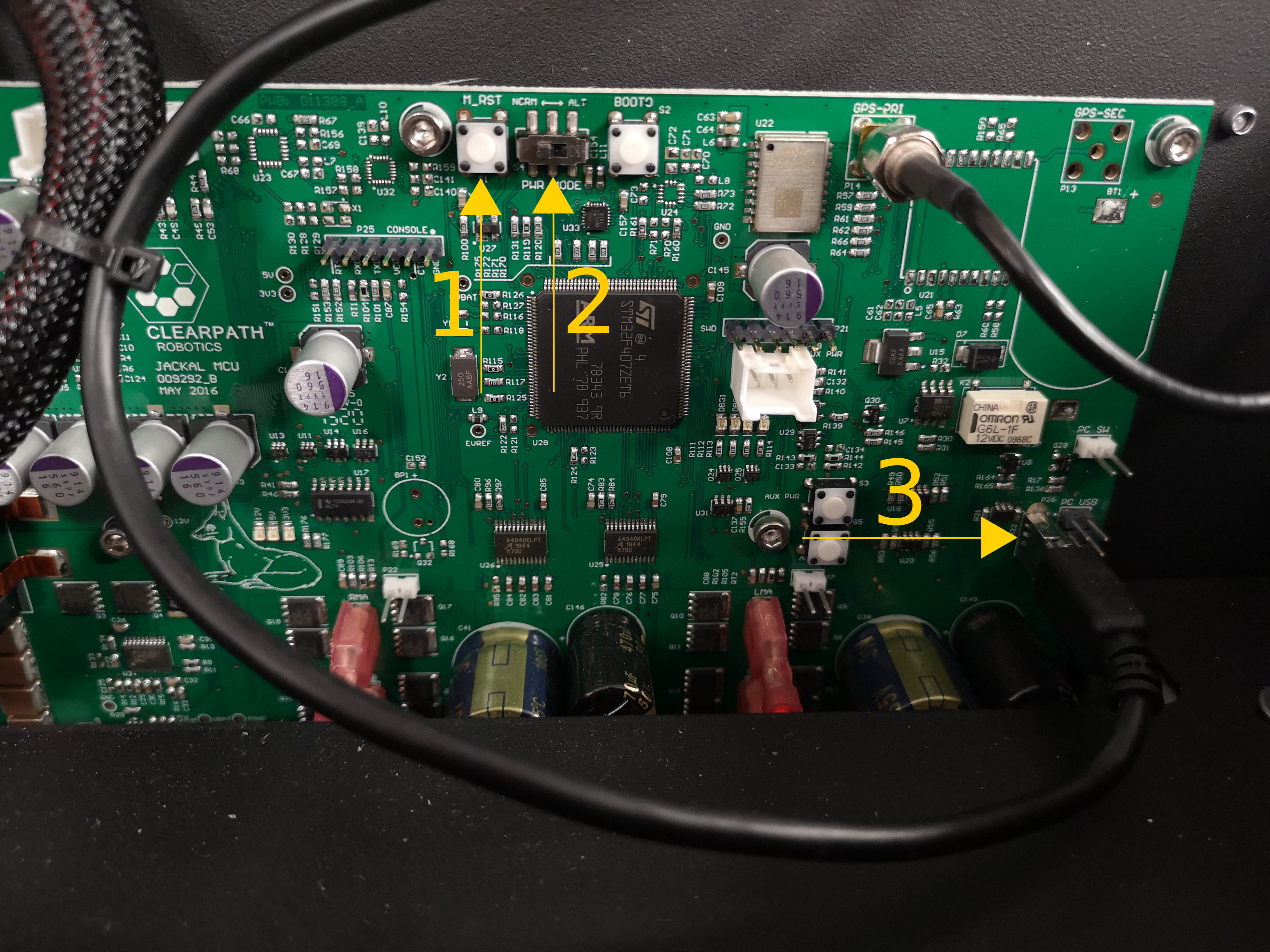
- The
M_RSTbutton, used to reset the MCU. - The
PWR_MODEswitch. Left isNORMor normal mode, right isALTor bootloader mode. This is used for flashing the firmware. - The mini-USB port used for transmitting data. This should be connected to J100's computer for both normal operation and firmware flashing.
Place the J100 MCU into bootloader mode
Open the lid of the robot to expose the MCU and make sure the mini-USB cable is connected to the robot computer.
Switch the PWR_MODE switch from NORM to ALT. If the robot is on, press the M_RST button. Otherwise, turn the robot on with the power button.
1. Download the Clearpath Firmware package from the Clearpath package server
On an external computer, run the following commands:
sudo apt-get update
sudo apt-get install ros-humble-clearpath-firmware
2. Prepare the Robot
Platforms with an Ethernet connection to the MCU have the option of flashing over USB or Ethernet. If you are updating to ROS 2 Humble for the first time, you must use USB. If you are updating ROS 2 Humble firmware to a newer version, using Ethernet is recommended. Skip this step if flashing over Ethernet.
The W200 MCU is located on the underside of the metal frame over the top of the computer.
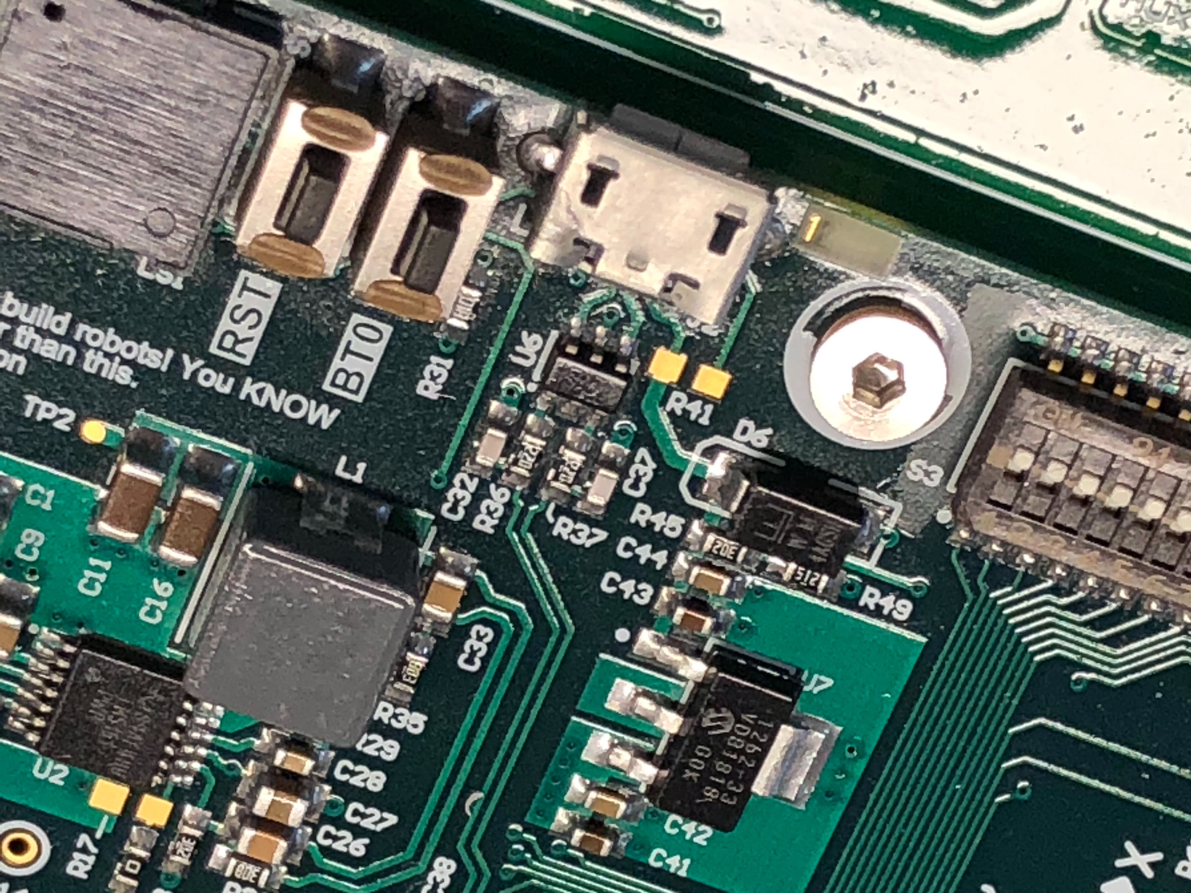
- The
RSTbutton, used to reset the MCU. - The
BT0button, used to enter the USB bootloader mode.
Place the W200 MCU into bootloader mode
While pressing BT0 on the MCU, connect the external computer to Warthog's MCU using a USB cable.
1. Download the Clearpath Firmware package from the Clearpath package server
On the robot computer, run the following commands:
sudo apt-get update
sudo apt-get install ros-humble-clearpath-firmware
2. Prepare the Robot
Platforms with an Ethernet connection to the MCU have the option of flashing over USB or Ethernet. If you are updating to ROS 2 Humble for the first time, you must use USB. If you are updating ROS 2 Humble firmware to a newer version, using Ethernet is recommended. Skip this step if flashing over Ethernet.
Place the R100 Ridgeback up on blocks. Firmware loading does not usually result in unintended motion, but it's safest when off the ground.
Remove the side panels to access the robot computer and MCU.
Connect the MCU to the R100 Ridgeback's onboard computer using a mini-USB cable connected to the port shown below:
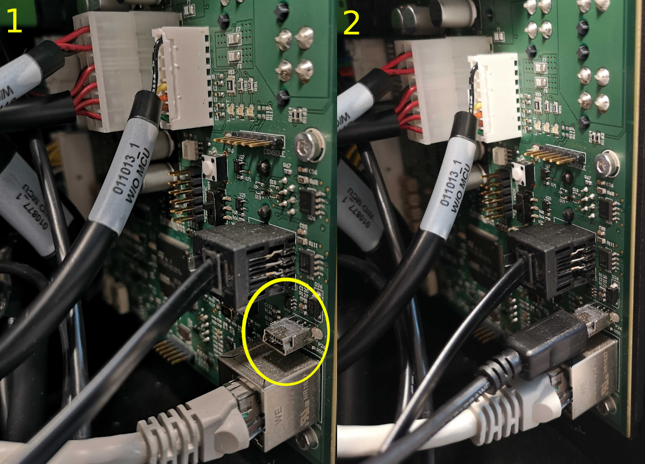
In the middle of the MCU, there is a two-position switch labelled PWR_MODE. Move the switch from the default NORM position to the AUX position.
Press the M_RST to restart the MCU. Now, the MCU is in boot-loader mode, ready to receive new firmware.
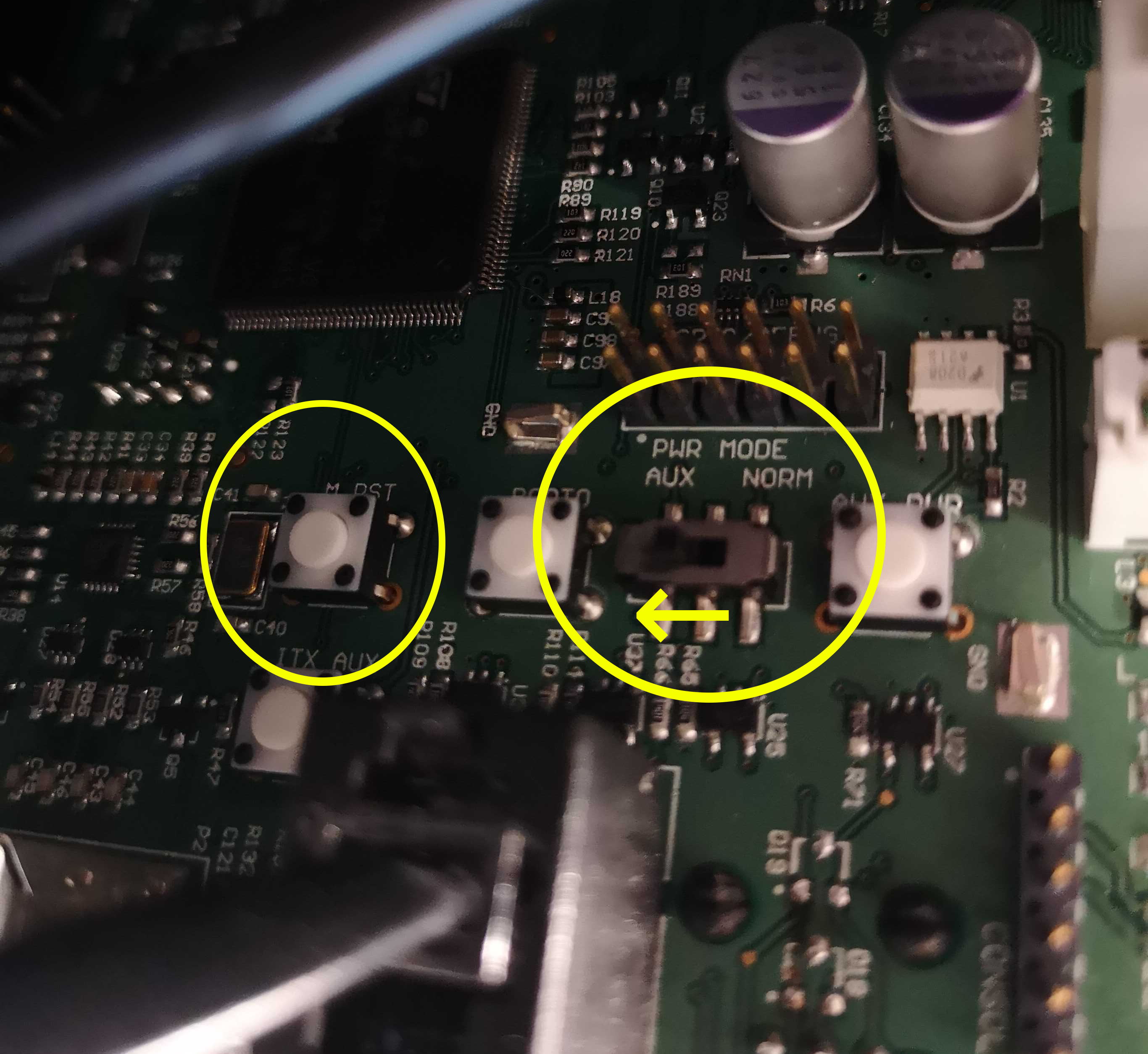
The Ridgeback's MCU is normally rotated 90 degrees when it is installed in the robot; the NORM position is typically towards the top of the robot's chassis and the AUX position is normally towards the bottom.
1. Download the Clearpath Firmware package from the Clearpath package server
On the robot computer, run the following commands:
sudo apt-get update
sudo apt-get install ros-humble-clearpath-firmware
2. Prepare the Robot
Platforms with an Ethernet connection to the MCU have the option of flashing over USB or Ethernet. If you are updating to ROS 2 Humble for the first time, you must use USB. If you are updating ROS 2 Humble firmware to a newer version, using Ethernet is recommended. Skip this step if flashing over Ethernet.
The DX100 MCU is mounted near the HMI panel towards the rear of the robot. To access it, remove the antennas and the center channel panel.
Connect the MCU to the onboard computer using a mini-USB cable connected to the port as shown below:
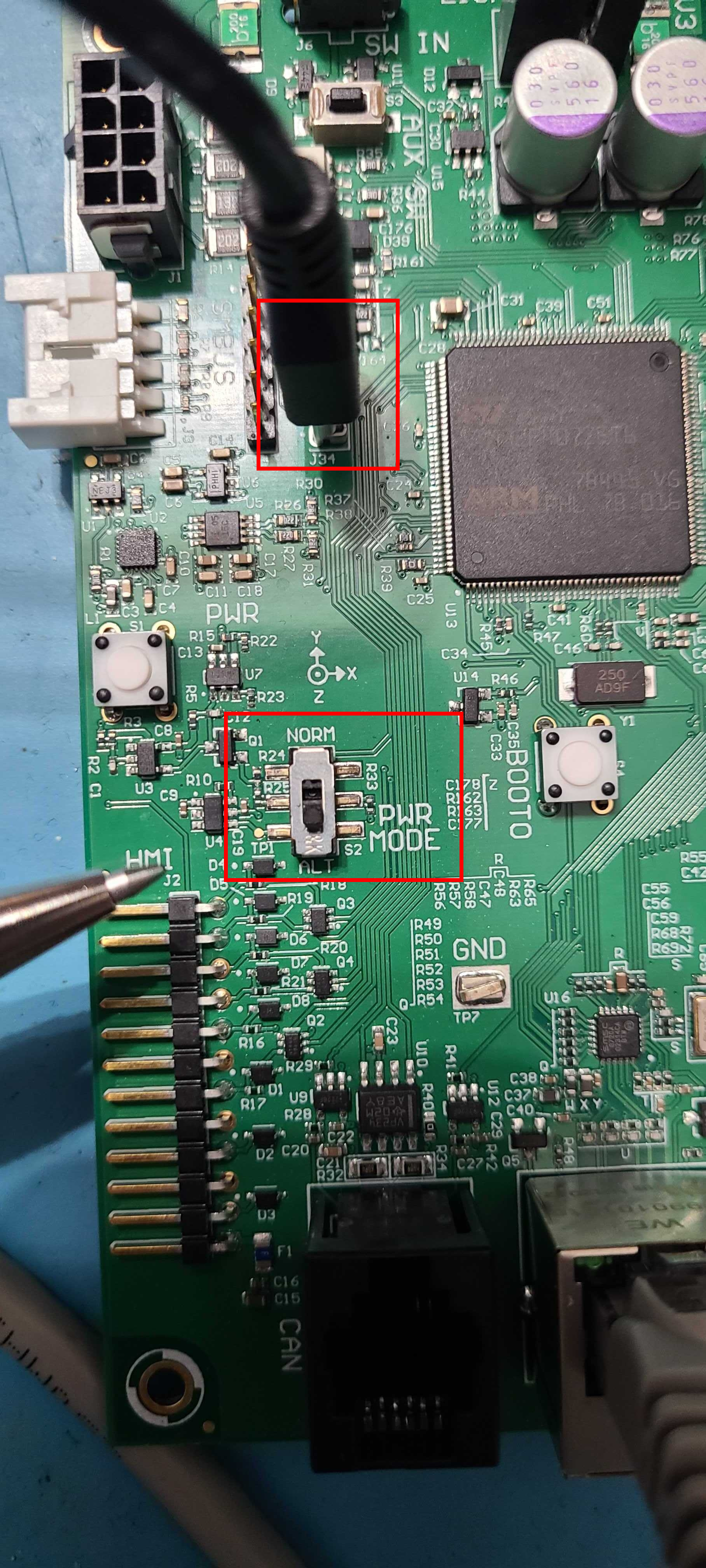
As is shown in the image above, set the PWR_MODE switch to the ALT position.
Press the M_RST or restart the robot using the HMI panel. Now, the MCU is in boot-loader mode, ready to receive new firmware.
1. Download the Clearpath Firmware package from the Clearpath package server
On the robot computer, run the following commands:
sudo apt-get update
sudo apt-get install ros-humble-clearpath-firmware
2. Prepare the Robot
Platforms with an Ethernet connection to the MCU have the option of flashing over USB or Ethernet. If you are updating to ROS 2 Humble for the first time, you must use USB. If you are updating ROS 2 Humble firmware to a newer version, using Ethernet is recommended. Skip this step if flashing over Ethernet.
The DX150 MCU is mounted near the HMI panel towards the rear of the robot. To access it, remove the antennas and the center channel panel.
Connect the MCU to the onboard computer using a mini-USB cable connected to the port as shown below:
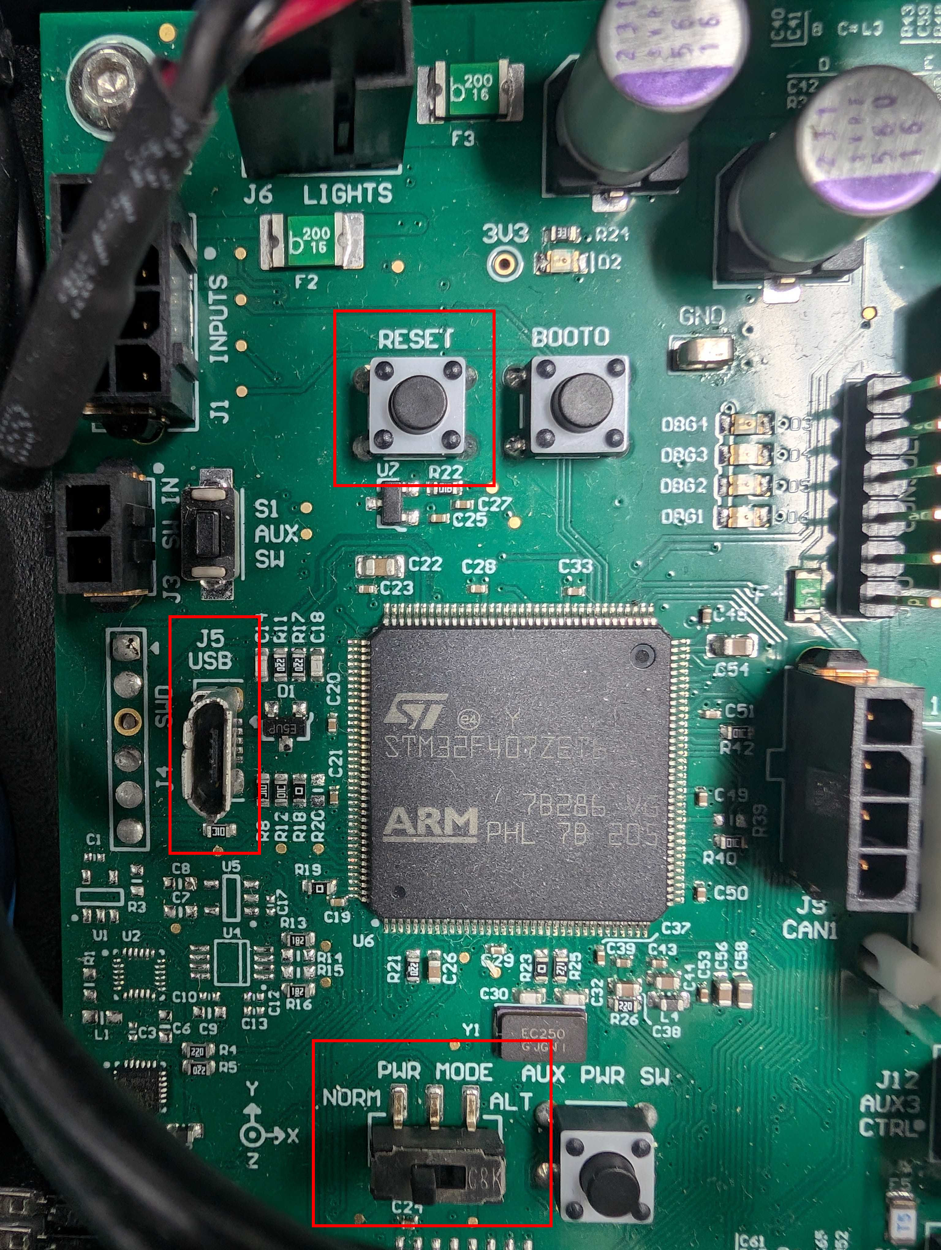
As is shown in the image above, set the PWR_MODE switch to the ALT position.
Press the M_RST or restart the robot using the HMI panel. Now, the MCU is in boot-loader mode, ready to receive new firmware.
3. Flash the firmware
Run the Clearpath firmware flash tool:
source /opt/ros/humble/setup.bash
ros2 run clearpath_firmware flash
Select your platform, then select which method of flashing you would like to use.
Do not turn the robot off or unplug the cable while flashing firmware. If an error occurs while flashing, you can attempt to flash again over USB.
4. Place the robot back into normal operating mode
If you flashed over Ethernet, skip this step.
- J100
- W200
- R100
- DX100
- DX150
Switch the PWR_MODE switch from ALT back to NORM. The robot will turn off.
Power it back on with the power button.
Press the RST button. The MCU should enter regular operation.
Switch the PWR_MODE switch from ALT back to NORM. The robot will turn off.
Power it back on with the power button.
Switch the PWR_MODE switch from ALT back to NORM. The robot will turn off.
Power it back on with the power button.
Switch the PWR_MODE switch from ALT back to NORM. The robot will turn off.
Power it back on with the power button.
Support
Clearpath is committed to your success. Please get in touch with us and we will do our best to get you rolling again quickly: support@clearpathrobotics.com.
To get in touch with a salesperson regarding Clearpath Robotics products, please email research-sales@clearpathrobotics.com.
If you have an issue that is specifically about ROS and is something which may be of interest to the broader community, consider asking it on https://robotics.stackexchange.com. If you do not get a satisfactory response, please ping us and include a link to your question as posted there. If appropriate, we will answer in the ROS Answers context for the benefit of the community.