Web UI Map Mode
Ensure that the Safety document has been read and the Operator is aware of possible hazards when using this product as well as the safety methods that can be used to stop the moving UGV.
The Map Mode of OutdoorNav Software uses a set of robotic navigation modules that allows the Operator(s) to define driveable paths and then execute missions using these maps. The UGV leverages these paths along with specified goal points to calculate a route. Operators can define one-way or two-way paths, speed limits for paths, allowable deviation distances from the paths and cost factors for each path.
Definitions
The list below defines what a "Map" and "Mission" are in relation to the Map mode view. The list also includes their relevant components. These terms are referred to throughout this page.
- Mission A Mission is a set of one or more Goalpoints.
- Map An Operator created map that goes over the aerial view and is used to define valid driveable areas for a mission.
- Point A map point used to help define a path.
- Path A connection between two points that the UGV can travel along for missions. Can be defined as one way or two way.
- Goalpoint A Goalpoint is a mission relevant geographical point referenced by its position relative to the datum in meters. These points are travelled to as part of the Mission.
- Task A Task is an automated activity or wait time implemented as a ROS action at a specific event or Goalpoint.
- GoToPoint A Goalpoint that is independant of a mission. This point is meant to be a one off position to send the UGV to.
- Ghost point A transparent point that is not part of the map. This point appears between two other points when in map edit mode. The Operator can drag and drop this ghost point to split a path. The newly created paths will keep the same properties as the path that was split (speed limit, cost factor, etc. )
Map Mode Bottom Bar

-
Map List: Contains the list of Maps that Operator(s) have created. The system also performs a health check of the map to ensure that the UGV can't get into a stuck state. This is shown with various icons by the map's name.
-
 Valid Map: Every path is reachable within the map and the UGV should not become trapped.
 -
 Disconnected Points:
The map contains points that will trap the UGV if it navigates to it. The best example of these are one-way paths that lead to dead ends.
Disconnected Points:
The map contains points that will trap the UGV if it navigates to it. The best example of these are one-way paths that lead to dead ends. -
 Disconnected Maps:
There are groups of paths that are not connected and are treated as separate maps. This may be desired by the Operator but it can lead to situations where the UGV has sections that aren't navigable.
Disconnected Maps:
There are groups of paths that are not connected and are treated as separate maps. This may be desired by the Operator but it can lead to situations where the UGV has sections that aren't navigable.
-
-
Path Type Button: The Path connection button that is used to set the type of path being connected between points (one-way/two-way). When in connection mode the button will be highlighted. To disable connection mode click the button or press the ESC key.
-
Point Drop Button: Drops a point at the UGV's current location. This action can also be accomplished by pressing Shift + P.
-
Mission List Contains the list of Missions that Operator(s) have created.
-
Goalpoint Drop Button: The Goalpoint indicator marker on the bottom bar allows the Operator to place a Goalpoint at the location of the UGV. This action can also be triggered by using the shortcut key combination Shift + X.
Map Creation
Before creating a mission the Operator will need to first create a map that the UGV can use to generate paths. First ensure that the UI is in "Map Edit Mode" (select the pencil icon in the bottom bar next to the map selection drop down). Open the drop down menu and select the "Add Map" option. From here the Operator can create a new map from scratch, clone the current map that is open or import a previously exported map. Once created the Operator can start placing points and building paths. If there are no maps in the system the Operator can also start placing points and the system will automatically create a map for them with default settings.
Map Points
To add points to the map, ensure that the UI is still in "Map Edit Mode" and click on the map. This will add a point to the map and also trigger the "Connection Mode". The path type button (one-way/two-way) will turn blue to indicate that the next point that is added will be connected to the previously created point. An Operator may cancel this connection by pressing the ESC key or by clicking the path type button. Points can be dragged and dropped to adjust their positions. To delete a point, right click the point and select Delete.
While in edit mode, Ghost points will appear in the center of each path that can be dragged and dropped to split the path.
Map Paths
Paths are generally added as part of the Point placement process as mentioned above. However, there may be cases where an Operator would like to connect existing points. To accomplish this, simply exit out of connection mode then click on the existing points. Once the first point is clicked on, connection mode will be re-established with the previously clicked point as the starting location.
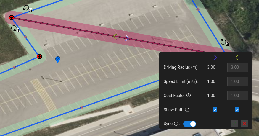
As paths are added they will be visible in the Map properties table, along with their relevant details. To edit a path's details an Operator can simply right click on the path or select the gear icon for the specific path in the table. This will open an overlay on the map that will allow the Operator to edit both one-way paths and two-way paths. In the case of two-way paths users can keep both ways in sync with each other or vary the properties depending on the direction.
Map Panel
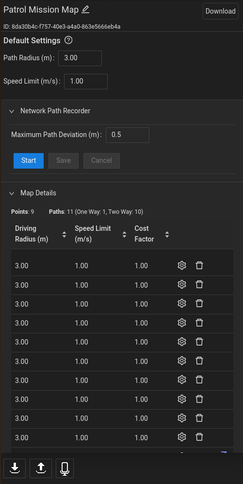
Enable the "Map Panel" toggle to open the details of the current map. This table will show the maps current default settings, the "Network Path Recorder" and the general map details. The Operator can modify the maps name, default path properties and edit path's through this view.
Rename Map
To rename the Map click the Map name as it appears in the upper left hand corner. This should change the text into an input box that can then be modified. Press enter/click aside to save the change.
Map Defaults
When adding paths the map uses defined default values to set the maximum driving radius and speed limit. If an Operator wishes to adjust these defaults this can be done here. This will only affect paths created after the changes have been made.
Network Path Recorder
An Operator can start a path recorder to place map points based on the UGV's position as it drives. As the UGV drives a preview path will be generated to show generally where the path will be placed. The Operator can then choose to save the path which will generate the relevant points and paths or cancel the recording which will remove the preview.
Map Details
The general map details includes the total number of points as well as a table that highlights each path within the map. Operators can delete paths or edit paths through this table as needed. If a path is one-way it will show a directional arrow next to it. Two-way paths are shown as a single row unless they are out of sync regarding their cost factor, speed limit or maximum driving radius.
Mission Creation�
To create a new Mission first ensure that the UI is in "Mission Edit Mode" ( select the rightmost pencil icon in the bottom bar). Then open the drop down menu in the bottom bar and select the "Add Mission" option. This will allow the Operator to create a new Mission which can then be defined with Goalpoints.
Goalpoint Mode
To add new Goalpoints to a Mission while edit mode is enabled select the "Goalpoint Mode" button. This will allow the Operator to place Goalpoints at locations where the Operator clicks on the map. These will appear as a circle with an arrow pointing in the direction the UGV will face upon arriving at the Goalpoint. The arrow can be rotated by holding the CTRL key and dragging the Goalpoint to the new direction. It can also be modified through the Mission Panel's Goalpoint Advanced Settings. When not holding the CTRL key the Goal point can be dragged and dropped to new locations in the same way as map Points.
Preview Path
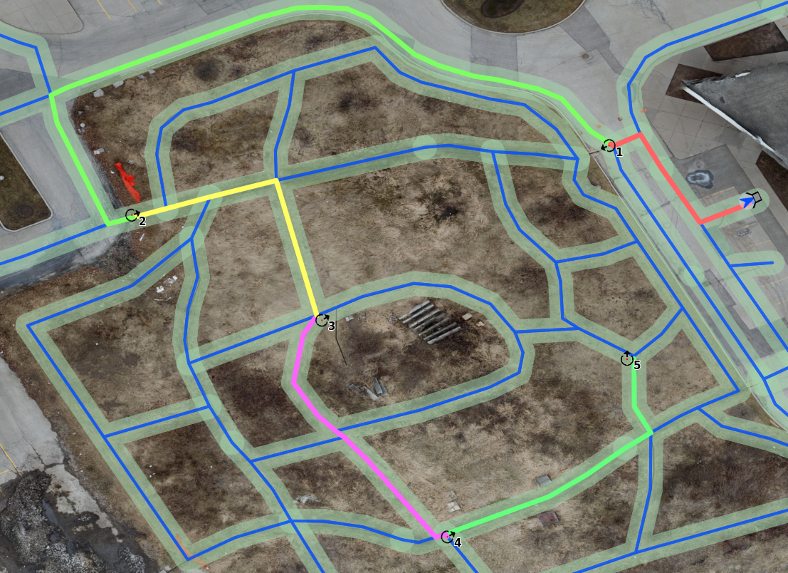
As Goalpoints are placed on the map the system will generate a path preview based on the UGV's location and the order the Goalpoints are placed in. This can be used to help determine the general route the UGV will attempt to take.
** In order for the UGV to reach the Goalpoint it must be on a reachable path. The preview path will look like a segmented red line for any points that the UGV cannot reach.**
Goalpoint Panel
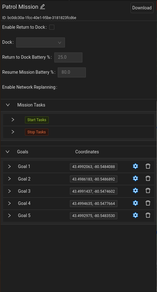
Enable the "Goalpoint Panel" toggle to open the list of available Goalpoints within the selected Mission as shown in the figure above. The Operator can now rearrange the list, add Tasks to the Goalpoints, and modify the final heading and/or tolerance of each Goalpoint. The Operator can also modify mission properties such as the mission name, a return to dock threshold, and apply Tasks to when the Mission starts and stops.
Rename Mission
To rename the Mission click the Mission name as it appears in the upper left hand corner. This should change the text into an input box that can then be modified. Press enter/click aside to save the change.
Return to Dock
An Operator may wish to add a flag to the mission to indicate when and if the UGV should return to the dock while executing the mission. When enabled, the Operator can input a battery percentage that once reached the UGV will begin navigating back to the specified dock or to the closest dock. They can then set the minimum battery life before the UGV is expected to resume the mission.
Mission Tasks
A Mission can have Tasks assigned to when it starts and when it stops. These Tasks will run in the order they are listed in and will always run whenever the Mission starts or stops.
Rearrange List of Goalpoints
Goalpoints can be rearranged in order of operation in the list. To do this, enable the "Goalpoints Panel" toggle to access the list of Goalpoints. Here, the Operator will be able to drag and drop the Goalpoints to reorder them.
Add Tasks to Goalpoint
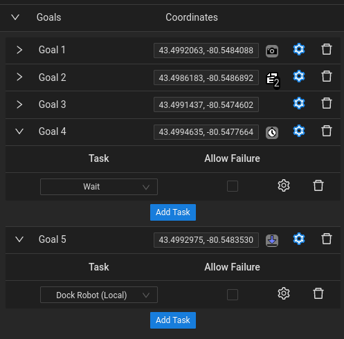
To add a Task to a Goalpoint:
-
Click the "+" icon (beside the Gear icon) in the Goalpoint row the Task is to be added to.
-
Click the "Add Task" button that has appeared.
-
Select the Task from the dropdown list. Standard Goalpoint icons will be decorated accordingly depending on the task selected. Goalpoints in the table will also have a small icon to indicate if tasks are assigned to the Goalpoint accordingly.
-
The check box next to the Task name controls mission behaviour in the event that the Task fails. If the checkbox is checked the Mission will proceed to the next step in it's process, such as the next task or navigating to the next Goalpoint. If its not checked, the Mission will become cancelled upon the Task's failure.
-
Click the Gear icon next to the selected Task to modify or add required Task testings.
Advanced Settings
Goalpoint Heading
When creating a Goalpoint, the Operator has the option of setting a final heading for the Goalpoint. For example, when creating a Goalpoint at an inspection point, the Operator may want the UGV to navigate and stop facing a certain direction. In Goalpoint Panel, the list of Goalpoints can be seen and the advanced settings of each Goalpoint can be accessed by clicking the "Gear" icon.
To set the Goalpoint's final heading, the Operator will need to check the "Final Heading Enabled" checkbox and enter the heading value in degrees. The heading indicator on the top bar can be used to help set this value. See the figure below showing the advanced settings.
Goalpoints that have a heading or tolerance assigned to them will show a different colour on their settings icon.
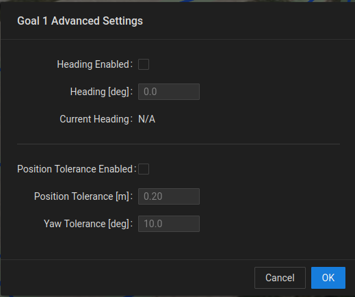
This heading is the same heading that is applied to the Goalpoint icon's arrow direction.
Goalpoint Tolerance
When creating a Mission, the Operator has the option of setting a specific tolerance for each Goalpoint. By default, the Goalpoint position and orientation tolerances are 0.3 meters and 180°, respectively. If a specific Goalpoint requires that the tolerances be either increased or decreased, these values can be modified in the advanced settings. For example, if it's required that the position and/or orientation at a Goalpoint be very accurate, such as 0.1 meters position and 5° orientation, or looser at 1.0 meter position, this can be done within these settings.
In Goalpoint Panel, the list of Goalpoints can be seen and the advanced settings of each Goalpoint can be accessed by clicking the "Gear" icon. To set the Goalpoint's tolerance, the Operator will need to check the "Goalpoint Tolerance Enabled" checkbox and enter the position and orientation values, in meters and degrees, respectively.
Mission Execution
Start Mission
In the bottom bar of the UI, the Operator has the ability to start the currently selected Mission by
clicking the "Play" button  .
.
When a Mission has been started the Play button will turn green.
Pause Mission
At the bottom of the UI, the Operator has the ability to pause the currently
running mission by clicking the "Pause" button  . When the
mission has been paused this button will turn yellow. Pausing a mission
allows the Operator to take time to look around with the camera or to
teleoperate the UGV to a nearby location to perform an inspection. For
ease of operation, the Operator must PAUSE the active mission if the Operator
wants to teleoperate the UGV.
. When the
mission has been paused this button will turn yellow. Pausing a mission
allows the Operator to take time to look around with the camera or to
teleoperate the UGV to a nearby location to perform an inspection. For
ease of operation, the Operator must PAUSE the active mission if the Operator
wants to teleoperate the UGV.
Cancel Mission/Task
At the bottom of the UI, the Operator has the ability to stop the currently
running mission or task by clicking the "Stop" button  . When the
mission/task has been cancelled this button will turn red. The name of
the mission/task will be shown to be cancelled in the feedback bar.
. When the
mission/task has been cancelled this button will turn red. The name of
the mission/task will be shown to be cancelled in the feedback bar.
Navigate to GoToPoint
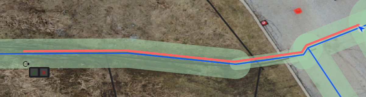
When a Map has been created a user can right click on a path or a path's driveable area to place a GoToPoint. This point will be a single point that will also create a small overlay to allow users to start or cancel the "Go To" execution. Before starting the execution the GoToPoint can be dragged to any driveable area or rotated using the CTRL key just like with Goalpoints.
A user can also right click on any Point of Interest that has the "Go To" tag and navigate to it in the same way.